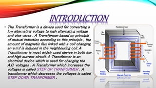
The document summarizes the working principles of transformers. It explains that a transformer works on the principle of mutual induction to convert alternating voltages from high to low or vice versa. Key points include:
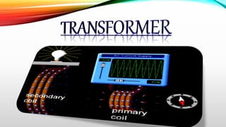
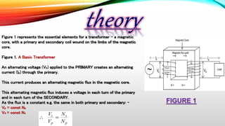
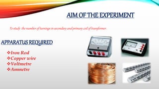
- Transformers have a primary coil connected to a voltage source and a secondary coil wound around an iron core.
- The changing magnetic field in the primary induces a voltage in the secondary.
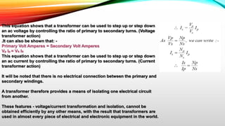
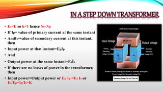
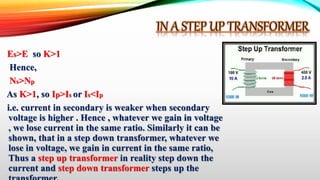
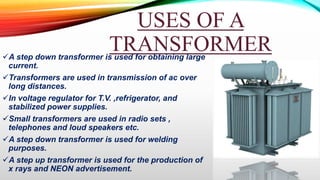
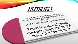
- The ratio of primary to secondary turns determines whether it is a step-up or step-down transformer.
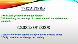
- Transformers experience energy losses such as copper losses, iron losses, and hysteresis losses, reducing their efficiency.