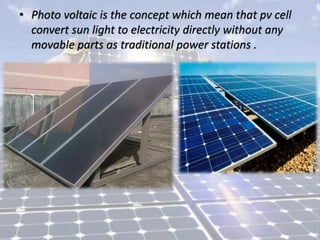
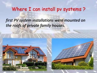
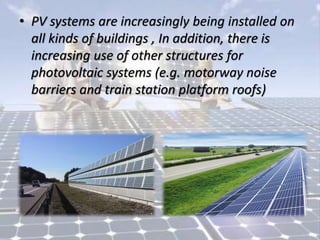
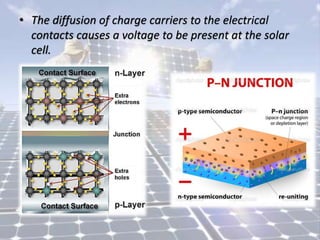
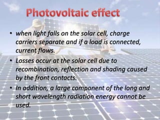
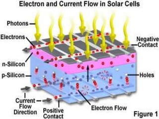
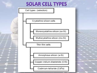
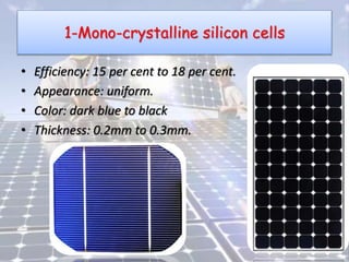
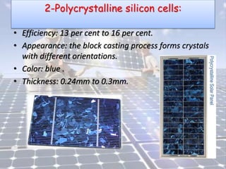
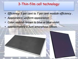
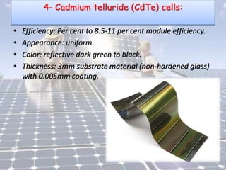
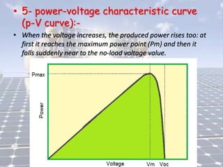
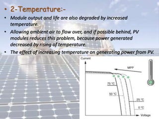
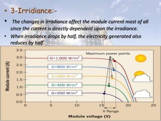
• Session 1
• Eng / Ahmed Abdel Baqi.
• Photo voltaic is the concept which mean that pv cell
convert sun light to electricity directly without any
movable parts as traditional power stations .
Where I can install pv systems ?
first PV system installations were mounted on
the roofs of private family houses.
• PV systems are increasingly being installed on
all kinds of buildings , In addition, there is
increasing use of other structures for
photovoltaic systems (e.g. motorway noise
barriers and train station platform roofs)
• The sun supplies energy in the form of
radiation, without which life on Earth could
not exist.
• The energy is generated in the sun's core through the
fusion of hydrogen atoms into helium.
• Part of the mass of the hydrogen is converted into
energy.
• In other words, the sun is an enormous nuclear fusion
reactor.
• Because the sun is such a long way from the Earth,
only a tiny proportion (around two-millionths) of the
sun's radiation reaches the Earth's surface.
• This works out at an amount of energy of 1 x 10¹⁸
kWh/m2.
Traditional energy sources
• 1- Natural Gas.
• 2- Crude oil.
• 3- Coal.
• All these energy sources that we use in our
industrial age are exhaustible.
• The amount of energy in the sunlight reaching the
Earth's surface is equivalent to around 10,000 times
the world's energy requirements.
• Consequently, only 0.01 per cent of the energy in
sunlight would need to be harnessed to cover
mankind total energy needs.
Distribution of solar radiation
• The intensity of solar radiation outside of the Earth's
atmosphere depends upon the distance between the
sun and the Earth.
• In the course of a year this varies between 1.47 x 10⁸
km and 1.52 x 10⁸ km.
• As a result, the irradiance EQ fluctuates between
1325W/m2 and 1412W/m2.
• The average value is referred to as the solar constant:
• Solar constant: EQ = 1367W/m2
Direct and diffuse radiation
• Sunlight on the Earth's surface comprises a direct
portion and a diffuse portion.
• The direct radiation comes from the direction of the
sun and casts strong shadows of objects.
• By contrast, diffuse radiation, which is scattered from
the dome of the sky, has no defined direction.
• Depending upon the cloud conditions and the time of
day (solar altitude), both the radiant power and the
proportion of direct and diffuse radiation can vary
greatly.
• On clear days the direct radiation accounts for the greater
part of the total radiation.
• On very cloudy days (especially in winter), the insolation is
almost entirely diffuse.
• In Germany, the proportion of diffuse insolation is 60 per cent
and direct radiation 40 per cent over the year.
How a solar cell works
• Highly pure silicon with a high crystal quality is
needed to make solar cells.
• The silicon atoms form a stable crystal lattice.
• Each silicon atom has four bonding electrons (valence
electrons) in its outer shell.
• To form a stable electron configuration, in each case
in the crystal lattice two electrons of neighboring
atoms form an electron pair bond.
• By forming electron pair bonds with four neighbors.
• We add some impurities to the silicon (or doping
atoms ).
• These atoms have one electron more (phosphorus) or
one electron less (boron) than silicon in their
outermost electron shell.
• In the case of phosphorus doping (n-doped), there is
a surplus electron for every phosphorus atom in the
lattice.
• This electron can move freely in the crystal and hence
transport an electric charge.
• With boron doping (p-doped), there is a hole (missing bonding
electron) for every boron atom in the lattice.
• Electrons from neighboring silicon atoms can fill this hole,
creating a new hole somewhere else.
• The diffusion of charge carriers to the electrical
contacts causes a voltage to be present at the solar
cell.
• when light falls on the solar cell, charge
carriers separate and if a load is connected,
current flows.
• Losses occur at the solar cell due to
recombination, reflection and shading caused
by the front contacts.
• In addition, a large component of the long and
short wavelength radiation energy cannot be
used.
1-Mono-crystalline silicon cells
• Efficiency: 15 per cent to 18 per cent.
• Appearance: uniform.
• Color: dark blue to black
• Thickness: 0.2mm to 0.3mm.
2-Polycrystalline silicon cells:
• Efficiency: 13 per cent to 16 per cent.
• Appearance: the block casting process forms crystals
with different orientations.
• Color: blue .
• Thickness: 0.24mm to 0.3mm.
3-Thin-film cell technology:
• Efficiency: 5 per cent to 7 per cent module efficiency .
• Appearance: uniform appearance.
• Color: reddish brown to blue or blue-violet.
• approximately 0.3um amorphous silicon.
4- Cadmium telluride (CdTe) cells:
• Efficiency: Per cent to 8.5-11 per cent module efficiency.
• Appearance: uniform.
• Color: reflective dark green to black.
• Thickness: 3mm substrate material (non-hardened glass)
with 0.005mm coating.
5- copper indium cells
• Efficiency: 12 per cent module efficiency.
6-Gallium arsenide
• Efficiency: 32 per cent module efficiency.
Comparison between the different types
1-Equivalent circuit diagrams of solar cells:
• A solar cell consisting of p-doped and n-doped silicon material
is in principle a large scale Silicon diode, both have similar
electrical properties.
• If a positive potential is present at the p-doped anode and a
negative potential is present at the n doped cathode, the
diode is connected in forward-biased direction.
• If the diode is connected in reverse-biased direction, current
flow is prevented in this direction.
• Only starting from a high breakdown voltage does the diode
become conductive, this can also lead to the destruction of the
diode.
• 1-Equivalent circuit diagrams of solar cells:
• When light hits the solar cell, the energy of the photons
generates free charge carriers.
• An illuminated solar cell constitutes a parallel circuit of a
power source and a diode.
• The power source produces the photoelectric current
(photocurrent) I p h .
• The level of this current depends upon the irradiance.
• 2- open circuit voltage :-
• The open-circuit voltage, VOC is the maximum
voltage available from a solar cell, and this
occurs at zero current.
• The open-circuit voltage corresponds to the
amount of forward bias on the solar cell due
to the bias of the solar cell junction with the
light-generated current.
• 2- open circuit voltage :-
• The open-circuit voltage is shown on the IV curve
below.
• 3- short circuit current :-
• The short-circuit current is the current through the solar
cell when the voltage across the solar cell is zero (i.e.,
when the solar cell is short circuited).
• Usually written as ISC , the short-circuit current is shown
on the IV curve below.
• 4- voltage-current characteristic curve (I-V
curve):-
• The voltage-current characteristic curve of a PV cell
is under short-circuit conditions the generated
current is at the highest (Isc).
• whereas with the circuit open the voltage (Voc=open
circuit voltage) is at the highest.
• Under the two above mentioned conditions the
electric power produced in the cell is null.
• 5- power-voltage characteristic curve
(p-V curve):-
• When the voltage increases, the produced power rises too: at
first it reaches the maximum power point (Pm) and then it
falls suddenly near to the no-load voltage value.
Important definitions:
• Mpp: - maximum power point. The maximum power point
(MPP) value is the point on the I-V curve at which the solar
cell works with maximum power.
• Impp: - current at maximum power point
• Vmpp: - voltage at maximum power point
• Voc: - open circuit voltage with crystalline cells, approximately
0.5V to 0.6V, and for amorphous cells is approximately 0.6V to
0.9V.
• Isc: - short circuit current is approximately 5 per cent to 15 per
cent higher than the MPP current with crystalline standard
cells (10cm x 10cm) under STC.
• FF: - fill factor it measures the quality of PV cell. If FF=1 this
means the best quality of PV cell.
Standard test conditions (STC):-
• Uniform conditions are specified for determining the
electrical data with which the solar cell characteristic
I-V curve is then calculated.
• 1- Vertical irradiance E of 1000 W/m2.
• 2- Cell temperature T of 25°C with a tolerance of ±
2°C.
• 3- Defined light spectrum (spectral distribution of the
solar reference irradiance.
Environmental Factors affecting on PV modules:-
• 1-Shading and dirt:-
• The effects of this shading are well known when even a
small portion of a cell, module, or array is shaded.
• 2-Temperature:-
• Module output and life are also degraded by increased
temperature.
• Allowing ambient air to flow over, and if possible behind, PV
modules reduces this problem, because power generated
decreased by rising of temperature.
• The effect of increasing temperature on generating power from PV.
• 3-Irridiance:-
• The changes in irradiance affect the module current most of all
since the current is directly dependent upon the irradiance.
• When irradiance drops by half, the electricity generated also
reduces by half.
Thank You
With my Best Wishes
Eng / Ahmed Abdel Baqi.

photo voltaic 1

  • 1.
    • Session 1 •Eng / Ahmed Abdel Baqi.
  • 2.
    • Photo voltaicis the concept which mean that pv cell convert sun light to electricity directly without any movable parts as traditional power stations .
  • 3.
    Where I caninstall pv systems ? first PV system installations were mounted on the roofs of private family houses.
  • 4.
    • PV systemsare increasingly being installed on all kinds of buildings , In addition, there is increasing use of other structures for photovoltaic systems (e.g. motorway noise barriers and train station platform roofs)
  • 5.
    • The sunsupplies energy in the form of radiation, without which life on Earth could not exist.
  • 6.
    • The energyis generated in the sun's core through the fusion of hydrogen atoms into helium. • Part of the mass of the hydrogen is converted into energy. • In other words, the sun is an enormous nuclear fusion reactor. • Because the sun is such a long way from the Earth, only a tiny proportion (around two-millionths) of the sun's radiation reaches the Earth's surface. • This works out at an amount of energy of 1 x 10¹⁸ kWh/m2.
  • 7.
    Traditional energy sources •1- Natural Gas. • 2- Crude oil. • 3- Coal. • All these energy sources that we use in our industrial age are exhaustible.
  • 8.
    • The amountof energy in the sunlight reaching the Earth's surface is equivalent to around 10,000 times the world's energy requirements. • Consequently, only 0.01 per cent of the energy in sunlight would need to be harnessed to cover mankind total energy needs.
  • 9.
    Distribution of solarradiation • The intensity of solar radiation outside of the Earth's atmosphere depends upon the distance between the sun and the Earth. • In the course of a year this varies between 1.47 x 10⁸ km and 1.52 x 10⁸ km. • As a result, the irradiance EQ fluctuates between 1325W/m2 and 1412W/m2. • The average value is referred to as the solar constant: • Solar constant: EQ = 1367W/m2
  • 10.
    Direct and diffuseradiation • Sunlight on the Earth's surface comprises a direct portion and a diffuse portion. • The direct radiation comes from the direction of the sun and casts strong shadows of objects. • By contrast, diffuse radiation, which is scattered from the dome of the sky, has no defined direction. • Depending upon the cloud conditions and the time of day (solar altitude), both the radiant power and the proportion of direct and diffuse radiation can vary greatly.
  • 12.
    • On cleardays the direct radiation accounts for the greater part of the total radiation. • On very cloudy days (especially in winter), the insolation is almost entirely diffuse. • In Germany, the proportion of diffuse insolation is 60 per cent and direct radiation 40 per cent over the year.
  • 13.
    How a solarcell works • Highly pure silicon with a high crystal quality is needed to make solar cells. • The silicon atoms form a stable crystal lattice. • Each silicon atom has four bonding electrons (valence electrons) in its outer shell. • To form a stable electron configuration, in each case in the crystal lattice two electrons of neighboring atoms form an electron pair bond. • By forming electron pair bonds with four neighbors.
  • 15.
    • We addsome impurities to the silicon (or doping atoms ). • These atoms have one electron more (phosphorus) or one electron less (boron) than silicon in their outermost electron shell. • In the case of phosphorus doping (n-doped), there is a surplus electron for every phosphorus atom in the lattice. • This electron can move freely in the crystal and hence transport an electric charge.
  • 16.
    • With borondoping (p-doped), there is a hole (missing bonding electron) for every boron atom in the lattice. • Electrons from neighboring silicon atoms can fill this hole, creating a new hole somewhere else.
  • 17.
    • The diffusionof charge carriers to the electrical contacts causes a voltage to be present at the solar cell.
  • 18.
    • when lightfalls on the solar cell, charge carriers separate and if a load is connected, current flows. • Losses occur at the solar cell due to recombination, reflection and shading caused by the front contacts. • In addition, a large component of the long and short wavelength radiation energy cannot be used.
  • 21.
    1-Mono-crystalline silicon cells •Efficiency: 15 per cent to 18 per cent. • Appearance: uniform. • Color: dark blue to black • Thickness: 0.2mm to 0.3mm.
  • 22.
    2-Polycrystalline silicon cells: •Efficiency: 13 per cent to 16 per cent. • Appearance: the block casting process forms crystals with different orientations. • Color: blue . • Thickness: 0.24mm to 0.3mm.
  • 23.
    3-Thin-film cell technology: •Efficiency: 5 per cent to 7 per cent module efficiency . • Appearance: uniform appearance. • Color: reddish brown to blue or blue-violet. • approximately 0.3um amorphous silicon.
  • 24.
    4- Cadmium telluride(CdTe) cells: • Efficiency: Per cent to 8.5-11 per cent module efficiency. • Appearance: uniform. • Color: reflective dark green to black. • Thickness: 3mm substrate material (non-hardened glass) with 0.005mm coating.
  • 25.
    5- copper indiumcells • Efficiency: 12 per cent module efficiency.
  • 26.
    6-Gallium arsenide • Efficiency:32 per cent module efficiency.
  • 27.
    Comparison between thedifferent types
  • 28.
    Comparison between thedifferent types
  • 29.
    1-Equivalent circuit diagramsof solar cells: • A solar cell consisting of p-doped and n-doped silicon material is in principle a large scale Silicon diode, both have similar electrical properties. • If a positive potential is present at the p-doped anode and a negative potential is present at the n doped cathode, the diode is connected in forward-biased direction. • If the diode is connected in reverse-biased direction, current flow is prevented in this direction. • Only starting from a high breakdown voltage does the diode become conductive, this can also lead to the destruction of the diode.
  • 30.
    • 1-Equivalent circuitdiagrams of solar cells:
  • 31.
    • 1-Equivalent circuitdiagrams of solar cells: • When light hits the solar cell, the energy of the photons generates free charge carriers. • An illuminated solar cell constitutes a parallel circuit of a power source and a diode. • The power source produces the photoelectric current (photocurrent) I p h . • The level of this current depends upon the irradiance.
  • 32.
    • 2- opencircuit voltage :- • The open-circuit voltage, VOC is the maximum voltage available from a solar cell, and this occurs at zero current. • The open-circuit voltage corresponds to the amount of forward bias on the solar cell due to the bias of the solar cell junction with the light-generated current.
  • 33.
    • 2- opencircuit voltage :- • The open-circuit voltage is shown on the IV curve below.
  • 34.
    • 3- shortcircuit current :- • The short-circuit current is the current through the solar cell when the voltage across the solar cell is zero (i.e., when the solar cell is short circuited). • Usually written as ISC , the short-circuit current is shown on the IV curve below.
  • 35.
    • 4- voltage-currentcharacteristic curve (I-V curve):- • The voltage-current characteristic curve of a PV cell is under short-circuit conditions the generated current is at the highest (Isc). • whereas with the circuit open the voltage (Voc=open circuit voltage) is at the highest. • Under the two above mentioned conditions the electric power produced in the cell is null.
  • 37.
    • 5- power-voltagecharacteristic curve (p-V curve):- • When the voltage increases, the produced power rises too: at first it reaches the maximum power point (Pm) and then it falls suddenly near to the no-load voltage value.
  • 38.
    Important definitions: • Mpp:- maximum power point. The maximum power point (MPP) value is the point on the I-V curve at which the solar cell works with maximum power. • Impp: - current at maximum power point • Vmpp: - voltage at maximum power point • Voc: - open circuit voltage with crystalline cells, approximately 0.5V to 0.6V, and for amorphous cells is approximately 0.6V to 0.9V. • Isc: - short circuit current is approximately 5 per cent to 15 per cent higher than the MPP current with crystalline standard cells (10cm x 10cm) under STC. • FF: - fill factor it measures the quality of PV cell. If FF=1 this means the best quality of PV cell.
  • 39.
    Standard test conditions(STC):- • Uniform conditions are specified for determining the electrical data with which the solar cell characteristic I-V curve is then calculated. • 1- Vertical irradiance E of 1000 W/m2. • 2- Cell temperature T of 25°C with a tolerance of ± 2°C. • 3- Defined light spectrum (spectral distribution of the solar reference irradiance.
  • 40.
    Environmental Factors affectingon PV modules:- • 1-Shading and dirt:- • The effects of this shading are well known when even a small portion of a cell, module, or array is shaded.
  • 41.
    • 2-Temperature:- • Moduleoutput and life are also degraded by increased temperature. • Allowing ambient air to flow over, and if possible behind, PV modules reduces this problem, because power generated decreased by rising of temperature. • The effect of increasing temperature on generating power from PV.
  • 42.
    • 3-Irridiance:- • Thechanges in irradiance affect the module current most of all since the current is directly dependent upon the irradiance. • When irradiance drops by half, the electricity generated also reduces by half.
  • 43.
    Thank You With myBest Wishes Eng / Ahmed Abdel Baqi.