Solar and WindPower generation
Dr. D.S. More
Associate Prof .
Electrical Engineering Department
Walchand College of Engineering.
SANGLI
E-mail: dsm.wce@gmail.com
2.
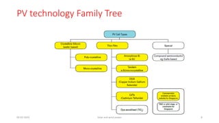
Content
• Introduction toSolar PV Module
• Solar PV cell
• Equivalent Circuit of PN Junction solar cell
• Characteristics of Solar Cell
• PV cell parameters
• Solar Array
05-02-2023 Solar and wind power 2
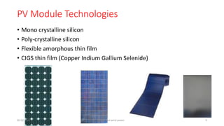
PV Module Technologies
•Mono crystalline silicon
• Poly-crystalline silicon
• Flexible amorphous thin film
• CIGS thin film (Copper Indium Gallium Selenide)
05-02-2023 Solar and wind power 9
10.
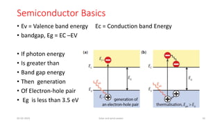
Semiconductor Basics
• Ev= Valence band energy Ec = Conduction band Energy
• bandgap, Eg = EC –EV
• If photon energy
• Is greater than
• Band gap energy
• Then generation
• Of Electron-hole pair
• Eg is less than 3.5 eV
05-02-2023 Solar and wind power 10
11.
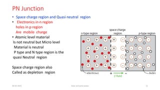
PN Junction
• Spacecharge region and Quasi neutral region
• Electronics in n region
holes in p region
Are mobile charge
• Atomic level material
Is not neutral but Micro level
Material is neutral
P type and N type region is the
quasi Neutral region
Space charge region also
Called as depletion region
05-02-2023 Solar and wind power 11
12.
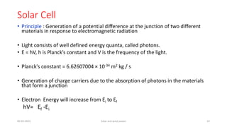
Solar Cell
• Principle: Generation of a potential difference at the junction of two different
materials in response to electromagnetic radiation
• Light consists of well defined energy quanta, called photons.
• E = hV, h is Planck’s constant and V is the frequency of the light.
• Planck's constant = 6.62607004 × 10⁻³⁴ m2 kg / s
• Generation of charge carriers due to the absorption of photons in the materials
that form a junction
• Electron Energy will increase from Ei to Ef
hV= Ef -Ei
05-02-2023 Solar and wind power 12
13.
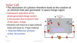
Solar Cell
• Theabsorption of a photon therefore leads to the creation of
an electron-hole pair generated in space charge region
• Subsequent separation of the
photo-generated charge carriers
in the junction due to electric field
of the space charge
• Electrons will move to n type material
holes will move to P type material
• Potential difference will built
across the junction
• .
05-02-2023 Solar and wind power 13
14.
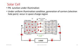
Solar Cell
• PNJunction under Illumination
• Under uniform illumination condition, generation of carriers (electron
hole pairs) occur in space charge region
05-02-2023 Solar and wind power 14
15.
Solar Cell
• Dueto electric field in the space charge region electrons will move
• at n side and similarly holes will move at P side.
• Thus electrons at n side and holes at P side will increase resulting in
voltage across the junction.
• This effect is called as photo voltaic effect.
05-02-2023 Solar and wind power 15
16.
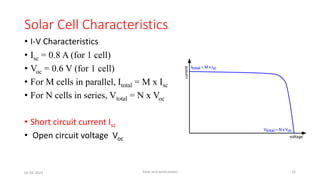
Solar Cell Characteristics
•I-V Characteristics
• Isc = 0.8 A (for 1 cell)
• Voc = 0.6 V (for 1 cell)
• For M cells in parallel, Itotal = M x Isc
• For N cells in series, Vtotal = N x Voc
• Short circuit current Isc
• Open circuit voltage Voc
05-02-2023 Solar and wind power 16
17.
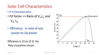
Solar Cell Characteristics
•P-V Characteristics
• Fill factor => Ratio of VmIm and
Voc Ioc
• Efficiency is ratio of o/p
power to i/p power.
Efficiency is 13 to 15 % for
Poly-crystalline silicon.
05-02-2023 Solar and wind power 17
18.
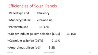
Efficiencies of SolarPanels
• Panel type and Efficiency
• Monocrystalline 20% and up
• Polycrystalline 15-17%
• Copper indium gallium selenide (CIGS) 13-15%
• Cadmium telluride (CdTe) 9-11%
• Amorphous silicon (a-Si) 6-8%
05-02-2023 Solar and wind power 18
19.
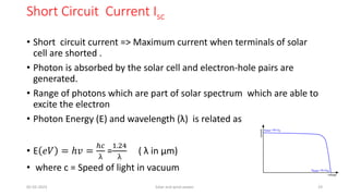
Short Circuit CurrentIsc
• Short circuit current => Maximum current when terminals of solar
cell are shorted .
• Photon is absorbed by the solar cell and electron-hole pairs are
generated.
• Range of photons which are part of solar spectrum which are able to
excite the electron
• Photon Energy (E) and wavelength (λ) is related as
• E 𝑒𝑉 = ℎ𝑣 =
ℎ𝑐
λ
=
1.24
λ
( λ in μm)
• where c = Speed of light in vacuum
05-02-2023 Solar and wind power 19
20.
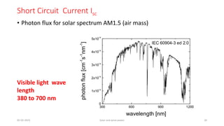
Short Circuit CurrentIsc
• Photon flux for solar spectrum AM1.5 (air mass)
05-02-2023 Solar and wind power 20
Visible light wave
length
380 to 700 nm
21.
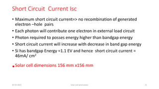
Short Circuit CurrentIsc
• Maximum short circuit current=> no recombination of generated
electron –hole pairs
• Each photon will contribute one electron in external load circuit
• Photon required to posses energy higher than bandgap energy
• Short circuit current will increase with decrease in band gap energy
• Si has bandgap Energy =1.1 EV and hence short circuit current =
46mA/ cm2
•Solar cell dimensions 156 mm x156 mm
05-02-2023 Solar and wind power 21
22.
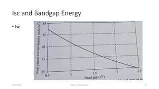
Isc and BandgapEnergy
• Isc
05-02-2023 Solar and wind power 22
23.
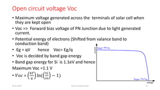
Open circuit voltageVoc
• Maximum voltage generated across the terminals of solar cell when
they are kept open
• Voc => Forward bias voltage of PN Junction due to light generated
current.
• Potential energy of electrons (Shifted from valance band to
conduction band)
• Eg = qV hence Voc= Eg/q
• Voc is decided by band gap energy
• Band gap energy for Si is 1.1eV and hence
Maximum Voc =1.1 V
• 𝑉𝑜𝑐 =
𝑘𝑇
𝑞
ln(
𝐼𝐿
𝐼𝑜
− 1)
05-02-2023 Solar and wind power 23
24.
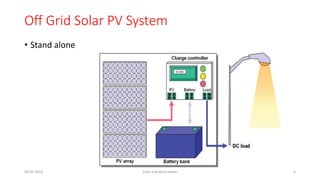
Open circuit voltageVoc
• 𝑉𝑜𝑐 = (𝑘𝑇/𝑞)ln[(𝐼𝐿/𝐼𝑜)−1]
• K = Boltzmann’s constant T=> PV cell operating temperature (oK)
• q= Electron charge Io = PV cell’s reverse saturation current (A)
• IL=cell output current
• For higher open circuit voltage = Io should be less
• Io is minimum when recombination rate is equal to the thermal
equilibrium recombination rate
• For Si solar cell Voc = 0.85 V
•
05-02-2023 Solar and wind power 24
25.
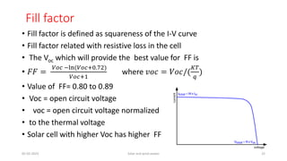
Fill factor
• Fillfactor is defined as squareness of the I-V curve
• Fill factor related with resistive loss in the cell
• The Voc which will provide the best value for FF is
• 𝐹𝐹 =
𝑉𝑜𝑐 −ln(𝑉𝑜𝑐+0.72)
𝑉𝑜𝑐+1
where 𝑣𝑜𝑐 = 𝑉𝑜𝑐/(
𝐾𝑇
𝑞
)
• Value of FF= 0.80 to 0.89
• Voc = open circuit voltage
• voc = open circuit voltage normalized
• to the thermal voltage
• Solar cell with higher Voc has higher FF
05-02-2023 Solar and wind power 25
26.
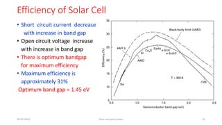
Efficiency of SolarCell
• Short circuit current decrease
with increase in band gap
• Open circuit voltage increase
with increase in band gap
• There is optimum bandgap
for maximum efficiency
• Maximum efficiency is
approximately 31%
Optimum band gap = 1.45 eV
05-02-2023 Solar and wind power 26
27.
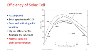
Efficiency of SolarCell
• Assumptions
• Solar spectrum AM1.5
• Solar cell with single PN
Junction
• Higher efficiency for
Multiple PN junctions
• Normal light, no
Light concentration
05-02-2023 Solar and wind power 27
AIR MASS
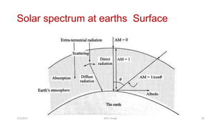
• Lesssolar radiations will reach when they travel a longer distance
through air mass ( Atmosphere)
• Morning and Evening => solar radiations will travel a longer distance
through air Mass
• Radiation spectrum outside the earth surface is AM0
• During Noon radiation spectrum is AM1
• If sun rays making angle θ with vertical then AM= 1/cosθ
•
30.
Losses in SolarCell- Fundamental losses
• Loss of low energy photons : Photons with less energy than bandgap
Energy will not be absorbed in the material. No generation elctron-
hole pairs. Transmission loss = 23%
• Loss due to excess energy of Photons: Excess energy will be given as a
heat to the material. Thermalization loss =33%
• Voltage loss: band gap voltage = Eg/q where as actual obtained
voltage is Voc . The ratio of Voc/(Eg/q)= 0.65 to 0.72.
• This happens due to recombination
• Fill factor loss: loss due to series and shunt resistance of the cell
• FF= 0.82 to 0.89
05-02-2023 Solar and wind power 30
31.
Losses in SolarCell- technological losses
• Loss by Reflection: Part of the incident photons is reflected from the
cell surface , minimized by anti reflecting coating and surface
texturing
• Loss due to incomplete absorption: loss of photons which have
enough energy to get absorbed in the cell, but do not get absorbed
due to limited thickness of cell. Minimized by light trapping scheme
• Loss due to metal coverage : contacts made with finger and busbar.
This metal contact shadows the light. It can be up to 10%
• Recombination loss: recombination occure in the bulk of material or
at the surface. Minimized => surface and bulk passivation technique
05-02-2023 Solar and wind power 31
32.
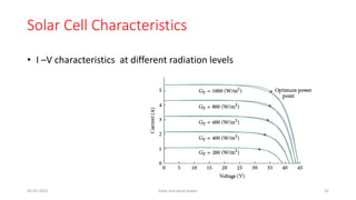
Solar Cell Characteristics
•I –V characteristics at different radiation levels
05-02-2023 Solar and wind power 32
33.
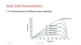
Solar Cell Characteristics
•P-V Characteristics at different solar radiations
05-02-2023 Solar and wind power 33
34.
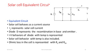
Solar cell EquivalentCircuit
• Equivalent Circuit
• Solar cell behaves as a current source
• IL represents solar cell current
• Diode D represents the recombination in base and emitter .
• I-V behaviors of diode with temp is represented
• Solar cell behavior with temp is also included.
• Ohmic loss in the cell is represented with Rs and Rsh
05-02-2023 Solar and wind power 34
35.
Solar cell EquivalentCircuit
• Equivalent Circuit
05-02-2023 Solar and wind power 35
36.
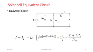
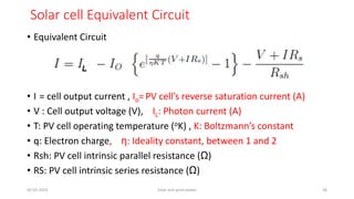
Solar cell EquivalentCircuit
• Equivalent Circuit
• I = cell output current , Io= PV cell’s reverse saturation current (A)
• V : Cell output voltage (V), IL: Photon current (A)
• T: PV cell operating temperature (oK) , K: Boltzmann’s constant
• q: Electron charge, η: Ideality constant, between 1 and 2
• Rsh: PV cell intrinsic parallel resistance (Ω)
• RS: PV cell intrinsic series resistance (Ω)
05-02-2023 Solar and wind power 36
37.
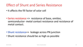
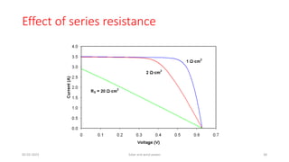
Effect of Shuntand Series Resistance
• It affects the fill factor of solar cell
• Series resistance => resistance of base, emitter,
semiconductor- metal contact resistance and resistance of
metal contact.
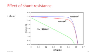
• Shunt resistance=> leakage across PN junction
• Shunt resistance should be as high as possible
05-02-2023 Solar and wind power 37
Effect of shuntresistance
• shunt
05-02-2023 Solar and wind power 39
40.
PV Cell, Modules& Arrays PV
Solar PV Cell
Module with 36 cells in
series
Array
05-02-2023 Solar and wind power 40
41.
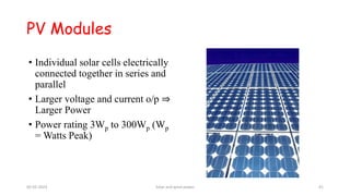
• Individual solarcells electrically
connected together in series and
parallel
• Larger voltage and current o/p ⇒
Larger Power
• Power rating 3Wp to 300Wp (Wp
= Watts Peak)
PV Modules
05-02-2023 Solar and wind power 41
42.
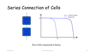
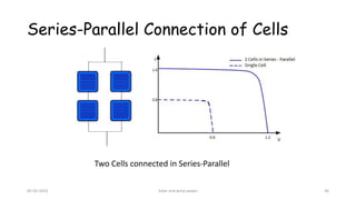
Series Connection ofCells
Two Cells connected in Series
05-02-2023 Solar and wind power 42
43.
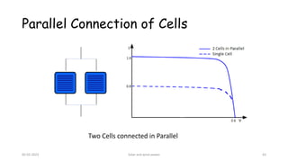
Parallel Connection ofCells
Two Cells connected in Parallel
05-02-2023 Solar and wind power 43
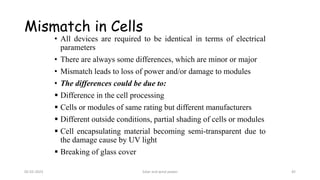
• All devicesare required to be identical in terms of electrical
parameters
• There are always some differences, which are minor or major
• Mismatch leads to loss of power and/or damage to modules
• The differences could be due to:
▪ Difference in the cell processing
▪ Cells or modules of same rating but different manufacturers
▪ Different outside conditions, partial shading of cells or modules
▪ Cell encapsulating material becoming semi-transparent due to
the damage cause by UV light
▪ Breaking of glass cover
Mismatch in Cells
05-02-2023 Solar and wind power 45
46.
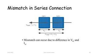
Mismatch in SeriesConnection
• Mismatch can occur due to difference in Voc and
Isc
05-02-2023 Solar and wind power 46
47.
Mismatch in SeriesConnection
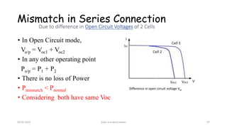
• In Open Circuit mode,
Vo/p = Voc1 + Voc2
• In any other operating point
Po/p = P1 + P2
• There is no loss of Power
• Pmismatch < Pnormal
• Considering both have same Voc
Difference in open circuit voltage Voc
05-02-2023 Solar and wind power 47
48.
Mismatch in SeriesConnection
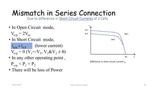
• In Open Circuit mode,
Vo/p = 2Voc
• In Short Circuit mode,
(lower current)
Vo/p = 0 (V1=-V2, V1&V2 ≠ 0)
• In any other operating point ,
Po/p < P1 + P2
• There will be loss of Power
Difference in short circuit current Isc
Io/p = Isc2
05-02-2023 Solar and wind power 48
49.
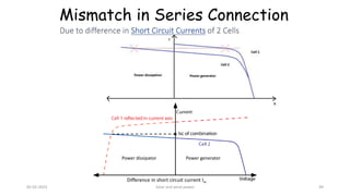
Mismatch in SeriesConnection
Difference in short circuit current Isc
Power generator
Power dissipator
05-02-2023 Solar and wind power 49
50.
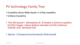
Mismatch in SeriesConnection
• Cell 2 is forced to go into reverse bias condition
• This is to maintain same current in the series combination
Forward biased current of cell 2 decreases
• Effective current increases (effective current = light generated
current – forward bias current)
• Power generated by cell 2 becomes negative [Power = I(-V) = -
IV]
• Cell 2 dissipates power instead of generating it
05-02-2023 Solar and wind power 50
51.
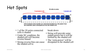
Hot Spots
• 1of the 10 series connected
cells is shaded
• Under SC condition, the
shaded cell will become
reverse biased
• Strong reverse bias can cause
the shaded cell to
break down
• String will provide some
output power but it will be
limited by the shaded cell
• The ‘extra power’ will be
dissipated in the shaded cell
05-02-2023 Solar and wind power 51
52.
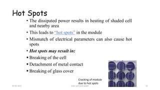
Hot Spots
• Thedissipated power results in heating of shaded cell
and nearby area
• This leads to “hot spots” in the module
• Mismatch of electrical parameters can also cause hot
spots
• Hot spots may result in:
▪ Breaking of the cell
▪ Detachment of metal contact
▪ Breaking of glass cover
Cracking of module
due to hot spots
05-02-2023 Solar and wind power 52
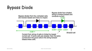
Bypass Diode
• Usedto avoid destructive effect of hot spots
• Connected in parallel with solar cells with opposite
polarity to that of solar cell
• In normal condition, the diode is reverse biased and
doesn’t conduct
• In shaded condition (for series connection), the reverse
bias will appear across the cell and the diode will be
forward biased
• Extra current generated by the non-shaded cells will pass
through the bypass diode
• Bypass diode avoids power dissipation in the cells
05-02-2023 Solar and wind power 54
55.
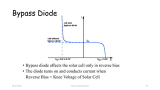
Bypass Diode
• Bypassdiode affects the solar cell only in reverse bias
• The diode turns on and conducts current when
Reverse Bias > Knee Voltage of Solar Cell
05-02-2023 Solar and wind power 55
56.
Bypass Diode
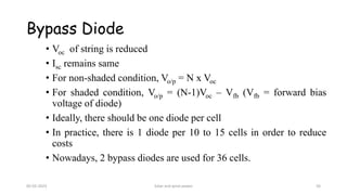
• Vocof string is reduced
• Isc remains same
• For non-shaded condition, Vo/p = N x Voc
• For shaded condition, Vo/p = (N-1)Voc – Vfb (Vfb = forward bias
voltage of diode)
• Ideally, there should be one diode per cell
• In practice, there is 1 diode per 10 to 15 cells in order to reduce
costs
• Nowadays, 2 bypass diodes are used for 36 cells.
05-02-2023 Solar and wind power 56
57.
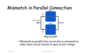
Mismatch in ParallelConnection
• Mismatch in parallel also occurs due to mismatch in
either short circuit current or open circuit voltage
05-02-2023 Solar and wind power 57
58.
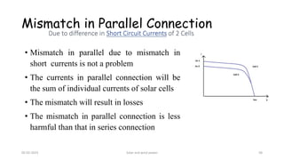
• Mismatch inparallel due to mismatch in
short currents is not a problem
• The currents in parallel connection will be
the sum of individual currents of solar cells
• The mismatch will result in losses
• The mismatch in parallel connection is less
harmful than that in series connection
Mismatch in Parallel Connection
05-02-2023 Solar and wind power 58
59.
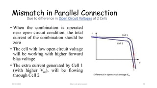
Mismatch in ParallelConnection
• When the combination is operated
near open circuit condition, the total
current of the combination should be
zero
• The cell with low open circuit voltage
will be working with higher forward
bias voltage
• The extra current generated by Cell 1
(with higher Voc), will be flowing
through Cell 2 Difference in open circuit voltage Voc
05-02-2023 Solar and wind power 59
60.
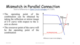
Mismatch in ParallelConnection
• The operating point of the
combination can be obtained by
taking the reflection or mirror image
of I-V curve with respect to the x-
axis as shown
• The crossover point of the curve will
be the operating point of the
combination
Difference in open circuit voltage Voc
05-02-2023 Solar and wind power 60
61.
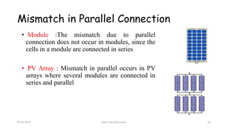
Mismatch in ParallelConnection
• Module :The mismatch due to parallel
connection does not occur in modules, since the
cells in a module are connected in series
• PV Array : Mismatch in parallel occurs in PV
arrays where several modules are connected in
series and parallel
05-02-2023 Solar and wind power 61
62.
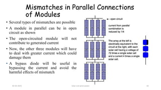
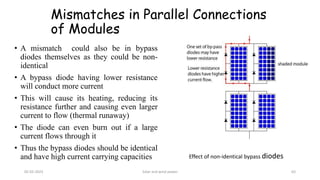
Mismatches in ParallelConnections
of Modules
• Several types of mismatches are possible
• A module in parallel can be in open
circuit as shown
• The open-circuited module will not
contribute to generated current
• Now, the other three modules will have
to deal with greater current which could
damage them
• A bypass diode will be useful in
bypassing the current and avoid the
harmful effects of mismatch
05-02-2023 Solar and wind power 62
63.
Mismatches in ParallelConnections
of Modules
• A mismatch could also be in bypass
diodes themselves as they could be non-
identical
• A bypass diode having lower resistance
will conduct more current
• This will cause its heating, reducing its
resistance further and causing even larger
current to flow (thermal runaway)
• The diode can even burn out if a large
current flows through it
• Thus the bypass diodes should be identical
and have high current carrying capacities Effect of non-identical bypass diodes
05-02-2023 Solar and wind power 63
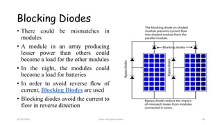
64.
• There couldbe mismatches in
modules
• A module in an array producing
lesser power than others could
become a load for the other modules
• In the night, the modules could
become a load for batteries
• In order to avoid reverse flow of
current, Blocking Diodes are used
• Blocking diodes avoid the current to
flow in reverse direction
Blocking Diodes
05-02-2023 Solar and wind power 64

![Open circuit voltage Voc
• 𝑉𝑜𝑐 = (𝑘𝑇/𝑞)ln[(𝐼𝐿/𝐼𝑜)−1]
• K = Boltzmann’s constant T=> PV cell operating temperature (oK)
• q= Electron charge Io = PV cell’s reverse saturation current (A)
• IL=cell output current
• For higher open circuit voltage = Io should be less
• Io is minimum when recombination rate is equal to the thermal
equilibrium recombination rate
• For Si solar cell Voc = 0.85 V
•
05-02-2023 Solar and wind power 24](https://image.slidesharecdn.com/chapter2solarpvmodule-260109101204-aa666c3a/85/Chapter-2-Solar-PV-Module-pdf-Solar-PV-Module-pdf-24-320.jpg)

![Mismatch in Series Connection
• Cell 2 is forced to go into reverse bias condition
• This is to maintain same current in the series combination
Forward biased current of cell 2 decreases
• Effective current increases (effective current = light generated
current – forward bias current)
• Power generated by cell 2 becomes negative [Power = I(-V) = -
IV]
• Cell 2 dissipates power instead of generating it
05-02-2023 Solar and wind power 50](https://image.slidesharecdn.com/chapter2solarpvmodule-260109101204-aa666c3a/85/Chapter-2-Solar-PV-Module-pdf-Solar-PV-Module-pdf-50-320.jpg)