Download to read offline
![IOSR Journal of Electronics and Communication Engineering (IOSR-JECE)
e-ISSN: 2278-2834,p- ISSN: 2278-8735.Volume 7, Issue 3 (Sep. - Oct. 2013), PP 61-66
www.iosrjournals.org
www.iosrjournals.org 61 | Page
Performance Comparison of Multi-Carrier CDMA Using
QPSK and BPSK Modulation
Karmjeet Singh1
, Er. Rajbir Kaur2
1
(Student University college of Engg, Punjabi University Patiala, India )
2
(Assist. Professor University college of Engg, Punjabi University Patiala)
Abstract: MC-CDMA (Multi Carrier Code Division Multiple Access) plays an important role in modern
wireless communications. Modern communication required an efficient spectrum usage and capacity and
throughput.MC-CDMA provided the solution of these problems. MIMO refers to links with multiple antennas at
the transmitter and receiver side. CDMA systems combined with multiple antennas is a promising technique,
beyond 3G and 4G wireless communications. MIMO provides spatial diversity, which mitigates the fading. The
usage of multiple antennas can significantly improve the performance of wireless communication system. This
work also derives simulation through MATLAB of average bit error rate verses bit energy to noise ratio of
multicarrier code division multiple access over Rayleigh channel using QPSK and BPSK modulation additive
white Gaussian noise.
Keywords: AWGN,BER,MC-CDMA, QPSK Modulation, Rayleigh Channel.
I. INTRODUCTION
Wireless communications is an emerging field, which has seen enormous growth in the last several
years. The growth of video, voice and data communication over the Internet, and the equally rapid pervasion of
mobile telephony, justifies expectations for mobile multimedia. Due to this growth of multimedia
communication, the users demanded high date rate communication systems in wireless environment where the
spectral resource is scarce. To fulfill the requirements new technologies like Code Division Multiple Access
and Orthogonal Frequency Division Multiplexing (OFDM) are few promising systems for the 4G
communication standards. Unique codes are used distinguish different users using same frequency band is the
basic idea behind CDMA. This led to an achievement of soft capacity with limitation self-interference and
Multiple User Interference (MUI). Thus the channel characteristics and spreading code characteristics which are
responsible for the above interference should be taken care to increase the capacity[1].
II. MULTI-CARRIER CDMA OVERVIEW
2.1. Multi-carrier CDMA (MC-CDMA)
Two main variations of the MC spread spectrum systems are the MC-CDMA (frequency domain
spreading) and MC direct sequence CDMA (MC-DS-CDMA) (time domain spreading). One way of looking at
MC-CDMA is as a combination of CDMA and OFDM, resulting in better frequency diversity and higher data
rates. In MC-CDMA, each symbol is spread using code chips and transmitted on several subcarriers. There is no
necessity for the number of carriers to be equal to the code length; thus offering a degree of flexibility in our
design.MC-DS-CDMA differs in the fact that the data is spread in time domain rather than in frequency; with
each sub channel representing a regular DS-CDMA system. The principle of MCCDMA is that a single data
symbol is transmitted over independent subcarriers. The eminent advantage of MC-CDMA is the increase in
bandwidth efficiency; the reason being the multiple access made possible through proper systems design using
orthogonal codes [2-3].
2.2. Need for MCCDMA
MC-CDMA takes advantage of both OFDM and CDMA and makes an effective efficient transmission
system by spreading the input data symbols with spreading codes in frequency domain. It uses a number of
narrowband orthogonal subcarriers with symbol duration longer than the delay spread. This makes it unlikely
for all the subcarriers to be affected by the same deep fades of the channel at the same time thereby performance
increases. During transmission becomes easier with longer symbol durations. As the number of paths increases
the performance of the two systems improves at first due to diversity, then, it starts to deteriorate due to the
increased interference from large number of paths of all users. In general, there is an optimum number of paths
that depends on the system used and the number of users. As the number of users increases, interference from all
users through all paths increases. Therefore, the optimum number of paths decreases [4].](https://image.slidesharecdn.com/k0736166-150319052720-conversion-gate01/85/Performance-Comparison-of-Multi-Carrier-CDMA-Using-QPSK-and-BPSK-Modulation-1-320.jpg)
![IOSR Journal of Electronics and Communication Engineering (IOSR-JECE)
e-ISSN: 2278-2834,p- ISSN: 2278-8735.Volume 7, Issue 3 (Sep. - Oct. 2013), PP 61-66
www.iosrjournals.org
www.iosrjournals.org 61 | Page
Performance Comparison of Multi-Carrier CDMA Using
QPSK and BPSK Modulation
Karmjeet Singh1
, Er. Rajbir Kaur2
1
(Student University college of Engg, Punjabi University Patiala, India )
2
(Assist. Professor University college of Engg, Punjabi University Patiala)
Abstract: MC-CDMA (Multi Carrier Code Division Multiple Access) plays an important role in modern
wireless communications. Modern communication required an efficient spectrum usage and capacity and
throughput.MC-CDMA provided the solution of these problems. MIMO refers to links with multiple antennas at
the transmitter and receiver side. CDMA systems combined with multiple antennas is a promising technique,
beyond 3G and 4G wireless communications. MIMO provides spatial diversity, which mitigates the fading. The
usage of multiple antennas can significantly improve the performance of wireless communication system. This
work also derives simulation through MATLAB of average bit error rate verses bit energy to noise ratio of
multicarrier code division multiple access over Rayleigh channel using QPSK and BPSK modulation additive
white Gaussian noise.
Keywords: AWGN,BER,MC-CDMA, QPSK Modulation, Rayleigh Channel.
I. INTRODUCTION
Wireless communications is an emerging field, which has seen enormous growth in the last several
years. The growth of video, voice and data communication over the Internet, and the equally rapid pervasion of
mobile telephony, justifies expectations for mobile multimedia. Due to this growth of multimedia
communication, the users demanded high date rate communication systems in wireless environment where the
spectral resource is scarce. To fulfill the requirements new technologies like Code Division Multiple Access
and Orthogonal Frequency Division Multiplexing (OFDM) are few promising systems for the 4G
communication standards. Unique codes are used distinguish different users using same frequency band is the
basic idea behind CDMA. This led to an achievement of soft capacity with limitation self-interference and
Multiple User Interference (MUI). Thus the channel characteristics and spreading code characteristics which are
responsible for the above interference should be taken care to increase the capacity[1].
II. MULTI-CARRIER CDMA OVERVIEW
2.1. Multi-carrier CDMA (MC-CDMA)
Two main variations of the MC spread spectrum systems are the MC-CDMA (frequency domain
spreading) and MC direct sequence CDMA (MC-DS-CDMA) (time domain spreading). One way of looking at
MC-CDMA is as a combination of CDMA and OFDM, resulting in better frequency diversity and higher data
rates. In MC-CDMA, each symbol is spread using code chips and transmitted on several subcarriers. There is no
necessity for the number of carriers to be equal to the code length; thus offering a degree of flexibility in our
design.MC-DS-CDMA differs in the fact that the data is spread in time domain rather than in frequency; with
each sub channel representing a regular DS-CDMA system. The principle of MCCDMA is that a single data
symbol is transmitted over independent subcarriers. The eminent advantage of MC-CDMA is the increase in
bandwidth efficiency; the reason being the multiple access made possible through proper systems design using
orthogonal codes [2-3].
2.2. Need for MCCDMA
MC-CDMA takes advantage of both OFDM and CDMA and makes an effective efficient transmission
system by spreading the input data symbols with spreading codes in frequency domain. It uses a number of
narrowband orthogonal subcarriers with symbol duration longer than the delay spread. This makes it unlikely
for all the subcarriers to be affected by the same deep fades of the channel at the same time thereby performance
increases. During transmission becomes easier with longer symbol durations. As the number of paths increases
the performance of the two systems improves at first due to diversity, then, it starts to deteriorate due to the
increased interference from large number of paths of all users. In general, there is an optimum number of paths
that depends on the system used and the number of users. As the number of users increases, interference from all
users through all paths increases. Therefore, the optimum number of paths decreases [4].](https://image.slidesharecdn.com/k0736166-150319052720-conversion-gate01/75/Performance-Comparison-of-Multi-Carrier-CDMA-Using-QPSK-and-BPSK-Modulation-1-2048.jpg)
![Performance Comparison of Multi-Carrier CDMA Using QPSK and BPSK Modulation
www.iosrjournals.org 62 | Page
III. Mc-Cdma Block Diagram
In this section we describe the transmitter and receiver model of MC-CDMSA system. Here symbols
are modulated on many subcarriers to introduce frequency diversity instead of using only one carrier like
CDMA. Thus MC-CDMA is robust against deep frequency selective fading compared to DS-CDMA[2].Each
user data is first spread using a given high rate spreading code in frequency domain. A fraction of the symbol
corresponding to a chip of the spreading code is transmitted through different subcarriers[5].
3.1. MCCDMA Transmitter Model
MC-CDMA transmitter is similar to OFDM transmitter with small difference. In OFDM many
different symbols are transmitted by subcarriers but in MC-CDMA same symbol is transmitted by different
subcarriers. The explanation of the above concept is clearly shown in figure1.The input data rate symbols are
converted to parallel streams. Then each parallel stream is spread using spreading codes like Walsh, Hadamard
etc.
Fig. 1. MCCDMA Transmitter
The OFDM system associated with the CDMA system converts the symbols to time domain samples
by Inverse Fast Fourier Transform (IFFT) and assigns a subcarrier for each symbol. Then the subcarriers are
multiplexed to form as a serial stream. Before the transmission the serial stream is converted to blocks and each
block is separated by a guard frame. The guard frame is usually a zero symbols or known symbols. In OFDM
the guard symbols are cyclic prefix of the block where a part of the symbols belonging to a block is appended
which has various advantages.
In this figure, the main difference between MCCDMA &OFDM is that the MC-CDMA scheme
transmits the same symbol in parallel through several subcarriers whereas the OFDM scheme transmits different
code of the user in the frequency domain. The input data stream is multiplied by the spreading code .The users
are separated by different codes. All data corresponding to the total number of sub carriers are modulated in
baseband by an inverse fast Fourier transform (IFFT) and converted back into serial data. Then, a cyclic prefix
is inserted between the symbols which is a repeat of the end of the symbols at beginning, to combat the inter-
symbol interference (ISI) and the inter-carrier interference (ICI) caused by multipath fading. And hence the
cyclic prefix length is chosen such that it is greater than the delay spread of the channel. In MC-CDMA
transmission, it is essential to have frequency non selective fading over each sub carrier. Therefore, if the
original symbol rate is high enough to become subject to frequency selective fading [6], the input data have to
be serial to parallel (SIP) converted into parallel data sequences and each SIP output is multiplied with the
spreading code of length GMC .In order to improve the performance of the system, an appropriate approach for
channel estimation is, to use dedicated pilot symbols that are periodically inserted in the transmission frame (in
the time domain) , also known as block-type pilot channel estimation. The pilot tones can also be inserted into
each symbol (in the frequency domain) with a given frequency spacing; this is known as comb-type pilot the
channel estimation[6-7].
3.2. MCCDMA Receiver model
The MCCDMA receiver configuration for the jth
user is shown in Figure 2. The received signal is first
down converted.](https://image.slidesharecdn.com/k0736166-150319052720-conversion-gate01/85/Performance-Comparison-of-Multi-Carrier-CDMA-Using-QPSK-and-BPSK-Modulation-2-320.jpg)
![Performance Comparison of Multi-Carrier CDMA Using QPSK and BPSK Modulation
www.iosrjournals.org 63 | Page
Fig. 2. MCCDMA Receiver
Then, the cyclic prefix is removed and the remaining samples are serial to parallel converted to obtain
the m-subcarriers components (corresponding to the ajp data), where m = 1,2, ... , GMC The m-subcarriers are
first demodulated by a fast Fourier transform and then multiplied by the gain qi to combine the received signal
energy scattered in the frequency domain
IV. Mimo Overview
MIMO systems use multiple antennas at both transmitter and receiver, so both transmit and receive
diversity are applied to mitigate fading resulting from signal fluctuations through the wireless channel. Based on
the degree at which the multiple data replicas are faded independently, the system provides diversity gains
representing the difference in SNR at the output of the diversity combiner compared to that of single branch
diversity at certain probability level. A MIMO system consisting of N transmit antenna elements equal to eight,
and of M receive antenna elements equal to two was modeled, accordingly diversity order of 16 can be
achieved. Combining the multiple versions of the signals created by different diversity schemes is needed for
improving the performance. The paper applies maximal ratio combining (MRC) technique using maximum-
likelihood (ML) decoder to combine these M received signals to resonate on the most likely transmitted signal.
The sum of the received SNRs form these M different paths is the effective received SNR of the system with
diversity M. The receiver needs to demodulate all M receive signals in case of MRC for a source with M
independent signals in the receive antennas[8-9].
V. Simulation Of Mc-Cdma
Here we discuss BER for QPSK in a Rayleigh multipath channel. In discussion on Rayleigh channel, a
circularly symmetric complex Gaussian random variable is considered which is of the form, h = hre + jhim where,
real and imaginary parts are zero mean independent and identically distributed (iid) Gaussian random variables
with mean 0 and variance ợ2
.The magnitude |h| which has a probability density, p(h) = h/ợ2
e-(2h/ợ2 )
,h≥0 is called
a Rayleigh random variable. This model, called Rayleigh fading channel model, is reasonable for an
environment where there are large number of reflectors.
The received signal in Rayleigh fading channel is of the form, y = hx+ n ,where ' y' is the received
symbol, h ' is complex scaling factor corresponding to Rayleigh multipath channel, 'x' is the transmitted
symbol(taking values +1' s and -1' s)and 'n' is the Additive White Gaussian Noise (A WGN) Assumptions:
1) The channel is flat fading - means that the multipath channel has only one tap. So, the convolution operation
reduces to a simple multiplication.
2) The channel is randomly varying in time – meaning each transmitted symbol gets multiplied by a randomly
varying complex number 'h' . Since 'h' is modeling a Rayleigh channel, the real and imaginary parts are
Gaussian distributed having mean 0 and variance 1/2.
3) The noise 'n' has the Gaussian probability density function with
P(n) = (1/ √ 2 πợ2
)e-(n-µ)2/2ợ2
,µ = 0 and ợ2
=N0/2 (1) .
4) T he channel ' h ' is known at the receiver. Equalization is performed at the receiver by dividing the received
symbol y by the h. ỳ= y/h= (hx+n)/ h= x + ṅ, where, ṅ= n/h his the additive noise scaled by the channel
coefficient.](https://image.slidesharecdn.com/k0736166-150319052720-conversion-gate01/85/Performance-Comparison-of-Multi-Carrier-CDMA-Using-QPSK-and-BPSK-Modulation-3-320.jpg)
![Performance Comparison of Multi-Carrier CDMA Using QPSK and BPSK Modulation
www.iosrjournals.org 64 | Page
5.1 Bit Error Rate
BER computation in A WGN, the probability of error for transmission of either + 1 or -1 is computed
by integrating the tail of the Gaussian probability density function for a given value of bit energy to noise ratio
Eb/ No. The bit error rate is,
Pb = 1/2 erfc(√( Eb/No )) (2)
.However in the presence of channel „ h ' , the effective bit energy to noise ratio is |h|(Eb/No). So the bit error
probability for a given value of „h' is,
Pb/h=1/2 erfc(√(|h|2
Eb/No ))=1/2erfc(√ᵞ) (3)
where ᵞ =|h|2
(Eb/No). To find the error probability over all random values of | h|2
, one must evaluate the
conditional probability density function Pb/h over the probability density function of ᵞ. [10].
5.2 Simulation model
Fig. 3. simulation model of MC-CDMA
We performs the following procedure: Initially we generate random QPSK modulated and BPSK modulation
symbols +1's and -l's, then we pass them through AWGN channel after that we demodulate the received symbol
based on the location in the constellation, then we count the number of errors finally repeat the same for
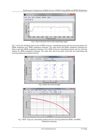
multiple Eb/No. Fig. 3 shows the simulation model of the MC-CDMA system. Fig. 4 shows the transmitted
signal. Fig. 5 shows the power level of the transmitting signal. And Fig. 6 shows the received signal.
Fig. 4 Transmitted signal](https://image.slidesharecdn.com/k0736166-150319052720-conversion-gate01/85/Performance-Comparison-of-Multi-Carrier-CDMA-Using-QPSK-and-BPSK-Modulation-4-320.jpg)
![Performance Comparison of Multi-Carrier CDMA Using QPSK and BPSK Modulation
www.iosrjournals.org 66 | Page
Fig 8 BER Using two transmitting antenna and two receiving antenna
VI. Conclusion
In this paper we have tried to study and implement the Multi- Carrier CDMA system using and derive
the BER Vs Eb/No performance for MCCDMA communication system using variable number of bits with QPSK
and BPSK modulation on Rayleigh channel and Additive White Gaussian Noise. Simulation of BER Vs Eb/No
with QPSK modulation shows that as BER performance decreases, the bit energy to noise ratio, Eb / No
increases. We noted that multiple with more numbers of antennas has better performances due to the antenna
diversity. Here in MIMO MCCDMA signals received will never be corrupted because copy of same signals are
transmitted over all subcarriers and error or overlapping of signals will never take place because of
orthogonality property
References
[1] Hara , S., &Prasad, R.(l999). “Design & perfonnance of MC-CDMA system in frequency-selectivefading channels”.IEEE Trans.
On Veh.Tech.48,(5) 1584-1595.
[2] Yee. N, Linnartz. J and Fettweis. G, “Multi- carrier CDMA for indoor wireless radio networks”, Proc. International Symposium
on PIMRC-93, 109-113,Sept 1993.
[3] DS-CDMA, MC-CDMA, MT-CDMA for Mobile Multi-Media communication Vehicular Technology Conference,1996. “Mobile
Technology for the Human Race”, IEEE 46th
.
[4] Lui, Hui (2000), “Signal processing application in CDMA communication”.
[5] Hara, Shinsuke and Prasad, Ramjee (1997), “Overview of Multicarrier CDMA”,IEEE Comm. Magazine, 35, 126.
[6] Hsieh, M.-H. and Wei, C.-H. (1998), “Channel estimation for OFDM systems based on comb-type pilot arrangement in frequency
selective fading channels”, IEEE Transactions on Consumer Electronics, 44,217.
[7] Coleri, S., Ergen, M., Puri, A., and Bahai, A. (2002), “A study of Channel estimation in OFDM systems”, In 56thIEEE Vehicular
Technology.
[8] A. Sharmila and Srigitha S. Nath,(2012) “Performance of MIMO Multi-Carrier CDMA with BPSK Modulation in Rayleigh
Channel”, ICCCE , 12 & 13 April, 2012.
[9] Maleki-Tehrani, A Hassibi, Cioffi, J.M, "Adaptive Equalization of Multiple input Multiple output (MIMO) frequency selective
channels", conference on Signals, Systems, and Computers, 1999, Vol. 1, pp. 547-551.
[10] Pragya Pallavi, Pradipta Dutta,”Muti-Carrier CDMA Overview with BPSK Modulation In Rayleigh Channel”, IEEE, 2010.](https://image.slidesharecdn.com/k0736166-150319052720-conversion-gate01/85/Performance-Comparison-of-Multi-Carrier-CDMA-Using-QPSK-and-BPSK-Modulation-6-320.jpg)

The document compares the performance of multi-carrier CDMA (MC-CDMA) using QPSK and BPSK modulation methods in wireless communications. It highlights the importance of using multiple antennas in MIMO systems to improve transmission reliability and efficiency in the presence of fading channels. Simulations demonstrate that QPSK modulation provides better bit error rates compared to BPSK, with increased performance observed through the use of multiple antennas.