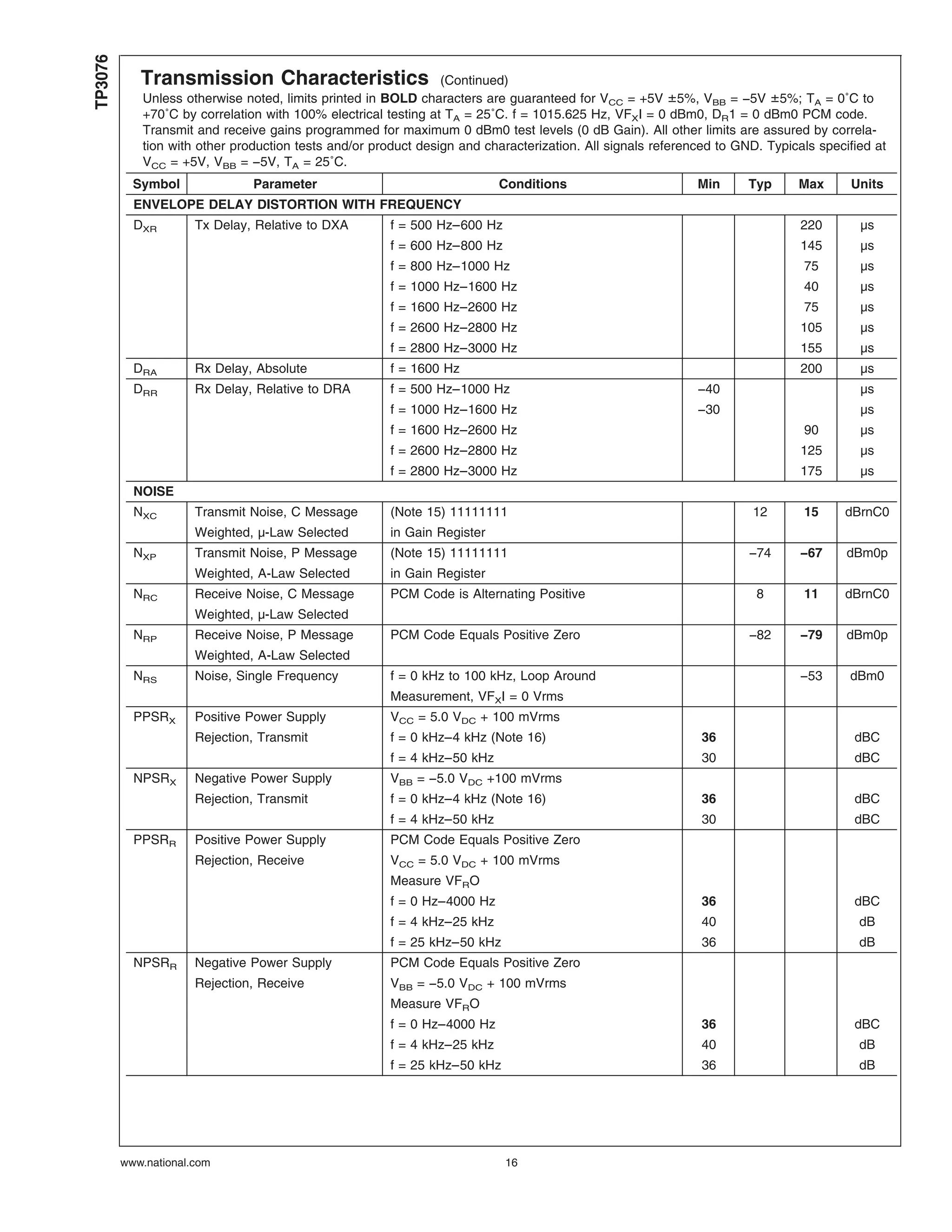
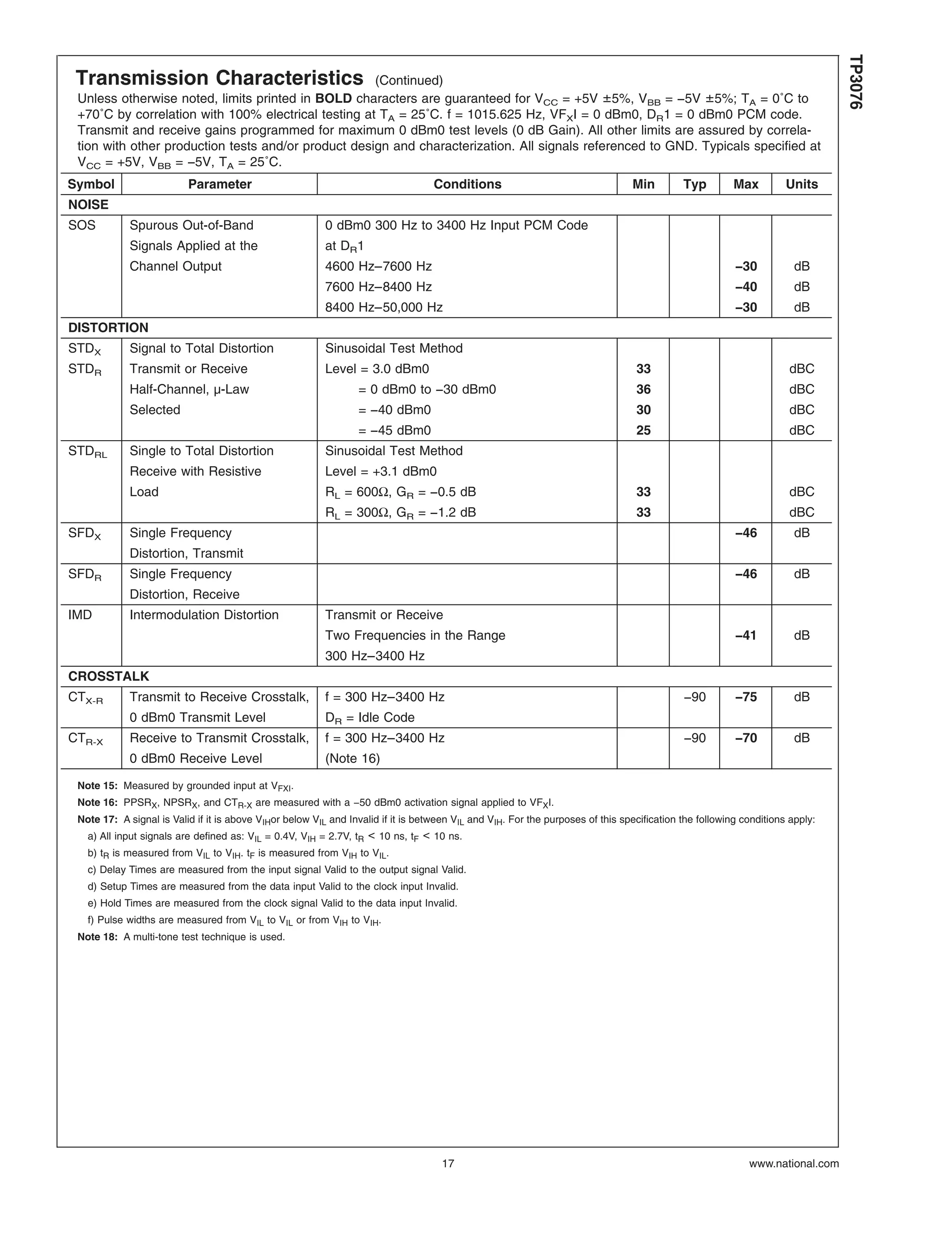
The TP3076 is a programmable PCM CODEC/filter chip optimized for digital switching applications and digital phones. It combines transmit and receive filters with an encoder, decoder, and programmable functions like gain control. It interfaces with solid-state subscriber line interface circuits (SLICs) and has a serial control interface for programming functions like gain, time slot assignment, and interface latch configuration.
This presentation explains various parameters used in AC drive of Allen Bradley Model Powerflex 4M
Unlock full featured course with 100+ Video Lectures at 30% Discount on "Advanced AC Drive- VFD, Stepper and Servo Drives" lifetime E-Learning course for 39 USD only: https://www.udemy.com/learn-vfd-in-a-day/?couponCode=slideshare2016
Enroll for Advanced Industrial Automation Training with PLC, HMI and Drive Combo with 300+ Video Lecture for 69.3 USD only: http://online.nfiautomation.org/catalog/1769?couponCode=LEARNING_MADE_EASY
In This PPT we are discussed about complete details of that product (Use,Operation, Technical details, Dimensions, Wiring, and etc..)
Please Support us and Follow our other Sites
https://www.instagram.com/controlsandsystems.offical
https://twitter.com/ControlsSystems
https://automationtechplc2.blogspot.com
https://humidificationcontrol.blogspot.com
https://controlsandsystems.business.site
www.controls.systemsdm@gmail.com
If you enjoyed this article, share it with your friends and colleagues
The Universal Asynchronous Receiver/Transmitter (UART) controller is the key component of the serial communications subsystem of a computer. The UART takes bytes of data and transmits the individual bits in a sequential fashion. At the destination, a second UART re-assembles the bits into complete bytes.
In This PPT we are discussed about complete details of that product (Use,Operation, Technical details, Dimensions, Wiring, and etc..)
Please Support us and Follow our other Sites
https://www.instagram.com/controlsandsystems.offical
https://twitter.com/ControlsSystems
https://automationtechplc2.blogspot.com
https://humidificationcontrol.blogspot.com
https://controlsandsystems.business.site
www.controls.systemsdm@gmail.com
If you enjoyed this article, share it with your friends and colleagues
The Universal Asynchronous Receiver/Transmitter (UART) controller is the key component of the serial communications subsystem of a computer. The UART takes bytes of data and transmits the individual bits in a sequential fashion. At the destination, a second UART re-assembles the bits into complete bytes.
Cataloge ge 3.control and_automation_dienhathe.com-4_13_vat300_e_c5-1_rev_bDien Ha The
Khoa Học - Kỹ Thuật & Giải Trí: http://phongvan.org
Tài Liệu Khoa Học Kỹ Thuật: http://tailieukythuat.info
Thiết bị Điện Công Nghiệp - Điện Hạ Thế: http://dienhathe.vn
Cataloge ge 3.control and_automation_dienhathe.com-4_14_vat300_e_c5-8_rev_bDien Ha The
Khoa Học - Kỹ Thuật & Giải Trí: http://phongvan.org
Tài Liệu Khoa Học Kỹ Thuật: http://tailieukythuat.info
Thiết bị Điện Công Nghiệp - Điện Hạ Thế: http://dienhathe.vn
Gene's law, Common gate, kernel Principal Component Analysis, ASIC Physical Design Post-Layout Verification, TSMC180nm, 0.13um IBM CMOS technology, Cadence Virtuoso, FPAA, in Spanish, Bruun E,
Lab 2: Cadence Tutorial on Layout and DRC/LVS/PEX
This section describes how to extract a netlist from your layout that includes parasitic resistances and capacitances. You will then be able to re-simulate your design with extracted parasitics in Spectre. PEX requires a clean LVS so that extracted parasitics can be correlated to nets on the schematic. Initiate the PEX interface by clicking on:Calibre > Run PEX
A window asking to load a runset file will now appear. Browse to the file
Step by step process of uploading presentation videos Hoopeer Hoopeer
Deep neural network, compressive sensing, floating gate techniques can be efficiently employed to increase voltage swing and reduce supply voltage requirements of class AB regulated cascode current mirrors, implement extreme low power analog circuits with this process. /also have good references for subthreshold region.
[Extreme Low Power Differential Pair: An Experimental Evaluation, Super-Gain-Boosted Miller Op-Amp based on Nested Regulated Cascode Techniques , Step by Step process of uploading presentation videos, Dennis Ritchie The creator of the C programming language and co-creator of Unix
Influential and powerful professional electrical and electronics engineering ...Hoopeer Hoopeer
powerful professional electrical and electronics engineering books
. Analysis and Design of Analog Integrated Circuits
Analysis and Design of Analog Integrated Circuits
Analog filter design
BJT and MOS, Advanced Circuit Topologies, concept of tracking, mm-Wave frequency beyond 30GHz, Bandgap is a stable, well defined, and constant current source
Understanding Inductive Bias in Machine LearningSUTEJAS
This presentation explores the concept of inductive bias in machine learning. It explains how algorithms come with built-in assumptions and preferences that guide the learning process. You'll learn about the different types of inductive bias and how they can impact the performance and generalizability of machine learning models.
The presentation also covers the positive and negative aspects of inductive bias, along with strategies for mitigating potential drawbacks. We'll explore examples of how bias manifests in algorithms like neural networks and decision trees.
By understanding inductive bias, you can gain valuable insights into how machine learning models work and make informed decisions when building and deploying them.
We have compiled the most important slides from each speaker's presentation. This year’s compilation, available for free, captures the key insights and contributions shared during the DfMAy 2024 conference.
Harnessing WebAssembly for Real-time Stateless Streaming PipelinesChristina Lin
Traditionally, dealing with real-time data pipelines has involved significant overhead, even for straightforward tasks like data transformation or masking. However, in this talk, we’ll venture into the dynamic realm of WebAssembly (WASM) and discover how it can revolutionize the creation of stateless streaming pipelines within a Kafka (Redpanda) broker. These pipelines are adept at managing low-latency, high-data-volume scenarios.
Using recycled concrete aggregates (RCA) for pavements is crucial to achieving sustainability. Implementing RCA for new pavement can minimize carbon footprint, conserve natural resources, reduce harmful emissions, and lower life cycle costs. Compared to natural aggregate (NA), RCA pavement has fewer comprehensive studies and sustainability assessments.
HEAP SORT ILLUSTRATED WITH HEAPIFY, BUILD HEAP FOR DYNAMIC ARRAYS.
Heap sort is a comparison-based sorting technique based on Binary Heap data structure. It is similar to the selection sort where we first find the minimum element and place the minimum element at the beginning. Repeat the same process for the remaining elements.
Cosmetic shop management system project report.pdfKamal Acharya
Buying new cosmetic products is difficult. It can even be scary for those who have sensitive skin and are prone to skin trouble. The information needed to alleviate this problem is on the back of each product, but it's thought to interpret those ingredient lists unless you have a background in chemistry.
Instead of buying and hoping for the best, we can use data science to help us predict which products may be good fits for us. It includes various function programs to do the above mentioned tasks.
Data file handling has been effectively used in the program.
The automated cosmetic shop management system should deal with the automation of general workflow and administration process of the shop. The main processes of the system focus on customer's request where the system is able to search the most appropriate products and deliver it to the customers. It should help the employees to quickly identify the list of cosmetic product that have reached the minimum quantity and also keep a track of expired date for each cosmetic product. It should help the employees to find the rack number in which the product is placed.It is also Faster and more efficient way.
6th International Conference on Machine Learning & Applications (CMLA 2024)ClaraZara1
6th International Conference on Machine Learning & Applications (CMLA 2024) will provide an excellent international forum for sharing knowledge and results in theory, methodology and applications of on Machine Learning & Applications.
Immunizing Image Classifiers Against Localized Adversary Attacksgerogepatton
This paper addresses the vulnerability of deep learning models, particularly convolutional neural networks
(CNN)s, to adversarial attacks and presents a proactive training technique designed to counter them. We
introduce a novel volumization algorithm, which transforms 2D images into 3D volumetric representations.
When combined with 3D convolution and deep curriculum learning optimization (CLO), itsignificantly improves
the immunity of models against localized universal attacks by up to 40%. We evaluate our proposed approach
using contemporary CNN architectures and the modified Canadian Institute for Advanced Research (CIFAR-10
and CIFAR-100) and ImageNet Large Scale Visual Recognition Challenge (ILSVRC12) datasets, showcasing
accuracy improvements over previous techniques. The results indicate that the combination of the volumetric
input and curriculum learning holds significant promise for mitigating adversarial attacks without necessitating
adversary training.
2. Connection Diagram
00975804
Order Number TP3076N-G
See NS Package Number N20A
Pin Descriptions
Pin Description
VCC +5V ±5% power supply.
VBB −5V ±5% power supply.
GND Ground. All analog and digital signals are referenced to this pin.
FSX Transmit Frame Sync input. Normally a pulse or squarewave with an 8 kHz repetition rate is applied
to this input to define the start of the transmit time slot assigned to this device (non-delayed data
timing mode), or the start of the transmit frame (delayed data timing mode using the internal time-slot
assignment counter).
FSR Receive Frame Sync input. Normally a pulse or squarewave with an 8 kHz repetition rate is applied to
this input to define the start of the receive time slot assigned to this device (non-delayed data timing
mode), or the start of the receive frame (delayed data timing mode using the internal time-slot
assignment counter).
BCLK Bit clock input used to shift PCM data into and out of the DR and DX pins. BCLK may vary from 64
kHz to 4.096 MHz in 8 kHz increments, and must be synchronous with MCLK.
MCLK Master clock input used by the switched capacitor filters and the encoder and decoder sequencing
logic. Must be 512 kHz, 1.536/1.544 MHz, 2.048 MHz or 4.096 MHz and synchronous with BCLK.
VFXI The Transmit analog high-impedance input. Voice frequency signals present on this input are
encoded as an A-law or µ-law PCM bit stream and shifted out on the selected DX pin.
VFRO The Receive analog power amplifier output, capable of driving load impedances as low as 300Ω
(depending on the peak overload level required). PCM data received on the assigned DR pin is
decoded and appears at this output as voice frequency signals.
DX1 This transmit data TRI-STATE® output remains in the high impedance state except during the
assigned transmit time slot on the assigned port, during which the transmit PCM data byte is shifted
out on the rising edges of BCLK.
TSX1 Normally this open drain output is floating in a high impedance state except when a time-slot is active
on the DX output, when the TSX1 output pulls low to enable a backplane line-driver.
DR1 This receive data input is inactive except during the assigned receive time slot of the assigned port
when the receive PCM data is shifted in on the falling edges of BCLK.
CCLK Control Clock input. This clock shifts serial control information into CI or out from CO when the CS
input is low, depending on the current instruction. CCLK may be asynchronous with the other system
clocks.
CI Control Data Input pin. Serial control information is shifted into COMBO II on this pin when CS is low.
Byte 1 of control information is always written into COMBO II, while the direction of byte 2 data is
determined by bit 2 of byte 1, as defined in Table 1
CO Control Data Output pin. Serial control or status information is shifted out of COMBO II on this pin
when CS is low.
TP3076
www.national.com 2
3. Pin Descriptions (Continued)
Pin Description
CS Chip Select input. When this pin is low, control information can be written to or read from COMBO II
via CI or CO.
IL3–IL0 Each Interface Latch I/O pin may be individually programmed as an input or an output determined by
the state of the corresponding bit in the Latch Direction Register (LDR). For pins configured as inputs,
the logic state sensed on each input is latched into the Interface Latch Register (ILR) whenever
control data is written to COMBO II, while CS is low, and the information is shifted out on the CO pin.
When configured as outputs, control data written into the ILR appears at the corresponding IL pins.
Functional Description
POWER-ON INITIALIZATION
When power is first applied, power-on reset circuitry initial-
izes the COMBO II and puts it into the power-down state.
The gain control registers for the transmit and receive gain
sections are programmed for no output, the power amp is
disabled and the device is in the non-delayed timing mode.
The Latch Direction Register (LDR) is pre-set with all IL pins
programmed as inputs, placing the SLIC interface pins in a
high impedance state. The CO pin is in TRI-STATE condi-
tion. Other initial states in the Control Register are indicated
in Section 2.0.
The desired modes for all programmable functions may be
initialized via the control port prior to a Power-up command.
POWER-DOWN STATE
Following a period of activity in the powered-up state the
power-down state may be re-entered by writing any of the
control instructions into the serial control port with the “P” bit
set to “1” as indicated in Table 1. It is recommended that the
chip be powered down before writing any additional instruc-
tions. In the power-down state, all non-essential circuitry is
de-activated and the DX1 output is in the high impedance
TRI-STATE condition.
The data stored in the Gain Control registers, the LDR and
ILR, and all control bits remain unchanged in the power-
down state unless changed by writing new data via the serial
control port, which remains active. The outputs of the Inter-
face Latches also remain active, maintaining the ability to
monitor and control the SLIC.
TRANSMIT FILTER AND ENCODER
The Transmit section input, VFXI, is a high impedance input.
No external components are necessary to set the gain.
Following this is a programmable gain/attenuation amplifier
which is controlled by the contents of the Transmit Gain
Register (see Programmable Functions section). An active
pre-filter then precedes the 3rd order high-pass and 5th
order low-pass switched capacitor filters. The A/D converter
has a compressing characteristic according to the standard
CCITT A or µ255 coding laws, which must be selected by a
control instruction during initialization (see Table 1 and Table
2). A precision on-chip voltage reference ensures accurate
and highly stable transmission levels. Any offset voltage
arising in the gain-set amplifier, the filters or the comparator
is canceled by an internal auto-zero circuit.
Each encode cycle begins immediately following the as-
signed Transmit time-slot. The total signal delay referenced
to the start of the time-slot is approximately 165 µs (due to
the Transmit Filter) plus 125 µs (due to encoding delay),
which totals 290 µs. Data is shifted out on DX1 during the
selected time slot on eight rising edges of BCLK.
DECODER AND RECEIVER FILTER
PCM data is shifted into the Decoder’s Receive PCM Reg-
ister via the DR1 pin during the selected time-slot on the 8
falling edges of BCLK. The Decoder consists of an expand-
ing DAC with either A or µ255 law decoding characteristic,
which is selected by the same control instruction used to
select the Encode law during initialization. Following the
Decoder is a 5th order low-pass switched capacitor filter with
integral Sin x/x correction for the 8 kHz sample and hold. A
programmable gain amplifier, which must be set by writing to
the Receive Gain Register, is included, and finally a Power
Amplifier capable of driving a 300Ω load to ±3.5V, a 600Ω
load to ±3.8V or a 15 kΩ load to ±4.0V at peak overload.
TABLE 1. Programmable Register Instructions
Function Byte 1 (Notes 1, 2, 3) Byte 2 (Note 1)
7 6 5 4 3 2 1 0 7 6 5 4 3 2 1 0
Single Byte Power-Up/Down P X X X X X 0 X None
Write Control Register P 0 0 0 0 0 1 X See Table 2
Read-Back Control Register P 0 0 0 0 1 1 X See Table 2
Write to Interface Latch Register P 0 0 0 1 0 1 X See Table 4
Read Interface Latch Register P 0 0 0 1 1 1 X See Table 4
Write Latch Direction Register P 0 0 1 0 0 1 X See Table 3
Read Latch Direction Register P 0 0 1 0 1 1 X See Table 3
Write Receive Gain Register P 0 1 0 0 0 1 X See Table 8
Read Receive Gain Register P 0 1 0 0 1 1 X See Table 8
TP3076
www.national.com3
4. Functional Description (Continued)
TABLE 1. Programmable Register Instructions (Continued)
Function Byte 1 (Notes 1, 2, 3) Byte 2 (Note 1)
7 6 5 4 3 2 1 0 7 6 5 4 3 2 1 0
Write Transmit Gain Register P 0 1 0 1 0 1 X See Table 7
Read Transmit Gain Register P 0 1 0 1 1 1 X See Table 7
Write Receive Time-Slot/Port P 1 0 0 1 0 1 X See Table 6
Read-Back Receive Time-Slot/Port P 1 0 0 1 1 1 X See Table 6
Write Transmit Time-Slot/Port P 1 0 1 0 0 1 X See Table 6
Read-Back Transmit Time-Slot/Port P 1 0 1 0 1 1 X See Table 6
Note 1: Bit 7 of bytes 1 and 2 is always the first bit clocked into or out from the CI or CO pin. X = don’t care.
Note 2: “P” is the power-up/down control bit, see Power-up/Down Control section. (“0” = Power Up, “1” = Power Down)
Note 3: Other register address codes are invalid and should not be used.
A decode cycle begins immediately after the assigned re-
ceive timeslot, and 10 µs later the Decoder DAC output is
updated. The total signal delay is 10 µs plus 120 µs (filter
delay) plus 62.5 µs (1⁄2 frame) which gives approximately
190 µs.
PCM INTERFACE
The FSX and FSR frame sync inputs determine the begin-
ning of the 8-bit transmit and receive time-slots respectively.
They may have any duration from a single cycle of BCLK
HIGH to one MCLK period LOW. Two different relationships
may be established between the frame sync inputs and the
actual time-slots on the PCM busses by setting bit 3 in the
Control Register (see Table 2). Non-delayed data mode is
similar to long-frame timing on the TP3050/60 series of
devices (COMBO); time-slots begin nominally coincident
with the rising edge of the appropriate FS input. The alter-
native is to use Delayed Data mode, which is similar to
shortframe sync timing on COMBO, in which each FS input
must be high at least a half-cycle of BCLK earlier than the
timeslot. The Time-Slot Assignment circuit on the device can
only be used with Delayed Data timing.
When using Time-Slot Assignment, the beginning of the first
time-slot in a frame is identified by the appropriate FS input.
The actual transmit and receive time-slots are then deter-
mined by the internal Time-Slot Assignment counters.
Transmit and Receive frames and time-slots may be skewed
from each other by any number of BCLK cycles. During each
assigned Transmit time-slot, the DX1 output shifts data out
from the PCM register on the rising edges of BCLK. TSX1
also pulls low for the first 71⁄2 bit times of the time-slot to
control the TRI-STATE Enable of a backplane line-driver.
Serial PCM data is shifted into the DR1 input during each
assigned Receive time-slot on the falling edges of BCLK.
SERIAL CONTROL PORT
Control information and data are written into or read-back
from COMBO II via the serial control port consisting of the
control clock CCLK, the serial data input, CI, and output, CO,
and the Chip Select input, CS. All control instructions require
2 bytes, as listed Table 1, with the exception of a single byte
power-up/down command. The Byte 1 bits are used as
follows: bit 7 specifies power up or power down; bits 6, 5, 4
and 3 specify the register address, bit 2 specifies whether
the instruction is read or write; bit 1 specifies a one or two
byte instruction; and bit 0 is not used.
To shift control data into COMBO II, CCLK must be pulsed
high 8 times while CS is low. Data on the CI input is shifted
into the serial input register on the falling edge of each CCLK
pulse. After all data is shifted in, the contents of the input
shift register are decoded, and may indicate that a 2nd byte
of control data will follow. This second byte may either be
defined by a second byte-wide CS pulse or may follow the
first contiguously, i.e, it is not mandatory for CS to return high
between the first and second control bytes. At the end of
CCLK8 in the 2nd control byte the data is loaded into the
appropriate programmable register. CS may remain low con-
tinuously when programming successive registers, if de-
sired. However, CS must be set high when no data transfers
are in progress.
To readback Interface Latch data or status information from
COMBO II, the first byte of the appropriate instruction is
strobed while CS is low, as defined in Table 1. CS must be
kept low, or be taken low again for a further 8 CCLK cycles,
during which the data is shifted onto the CO pin on the rising
edges of CCLK. When CS is high the CO pin is in the
high-impedance TRI-STATE, enabling the CI and CO pins of
many devices to be multiplexed together.
If CS returns high during either byte 1 or byte 2 before all
eight CCLK pulses of that byte occur, both the bit count and
byte count are reset and register contents are not affected.
This prevents loss of synchronization in the control interface
as well as corruption of register data due to processor inter-
rupt or other problem. When CS returns low again, the
device will be ready to accept bit 1 of byte 1 of a new
instruction.
Programmable Functions
POWER-UP/DOWN CONTROL
Following power-on initialization, power-up and power-down
control may be accomplished by writing any of the control
instructions listed in Table 1 into COMBO II with the “P” bit
set to “0” for power-up or “1” for power-down. Normally it is
recommended that all programmable functions be initially
programmed while the device is powered down. Power state
control can then be included with the last programming
instruction or the separate single-byte instruction. Any of the
programmable registers may also be modified while the
device is powered-up or down by setting the “P” bit as
indicated. When the power-up or down control is entered as
a single byte instruction, bit one (1) must be reset to a 0.
When a power-up command is given, all de-activated circuits
are activated, but the TRI-STATE PCM output(s), DX1 will
remain in the high impedance state until the second FSX
pulse after power-up.
TP3076
www.national.com 4
5. Programmable Functions (Continued)
CONTROL REGISTER INSTRUCTION
The first byte of a READ or WRITE instruction to the Control
Register is as shown in Table 1. The second byte has the
following bit functions:
TABLE 2. Control Register Byte 2 Functions
Bit Number and Name
7 6 5 4 3 2 1 0 Function
F1 F0 MA IA DN DL AL PP
0 0 MCLK = 512 kHz
0 1 MCLK = 1.536 MHz
or 1.544 MHz
1 0 MCLK = 2.048 MHz
(Note 4)
1 1 MCLK = 4.096 MHz
0 X Select µ255 Law
(Note 4)
1 0 A-Law, Including
Even Bit
Inversion
1 1 A-Law, No Even Bit
Inversion
0 Delay Data Timing
1 Non-Delayed
Data Timing (Note
4)
0 0 Normal Operation
(Note 4)
1 X Digital Loopback
0 1 Analog Loopback
0 Power Amp
Enabled in PDN
1 Power Amp
Disabled in PDN
(Note 4)
Note 4: state at power-on initialization.
Master Clock Frequency Selection
A Master clock must be provided to COMBO II for operation
of the filter and coding/decoding functions. The MCLK fre-
quency must be either 512 kHz, 1.536 MHz, 1.544 MHz,
2.048 MHz, or 4.096 MHz and must be synchronous with
BCLK. Bits F1 and F0 (see Table 2) must be set during
initialization to select the correct internal divider.
Coding Law Selection
Bits “MA” and “IA” in Table 2 permit the selection of µ255
coding or A-law coding, with or without even bit inversion.
Analog Loopback
Analog Loopback mode is entered by setting the “AL” and
“DL” bits in the Control Register as shown in Table 2. In the
analog loopback mode, the Transmit input VFXI is isolated
from the input pin and internally connected to the VFRO
output, forming a loop from the Receive PCM Register back
to the Transmit PCM Register. The VFRO pin remains active,
and the programmed settings of the Transmit and Receive
gains remain unchanged, thus care must be taken to ensure
that overload levels are not exceeded anywhere in the loop.
Digital Loopback
Digital Loopback mode is entered by setting the “AL” and
“DL” bits in the Control Register as shown in Table 2. This
mode provides another stage of path verification by enabling
data written into the Receive PCM Register to be read back
from that register in any Transmit time-slot at DX1. PCM
decoding continues and analog output appears at VFR0. The
output can be disabled by programming ‘No Output’ in the
Receive Gain Register (see Table 8).
INTERFACE LATCH DIRECTIONS
Immediately following power-on, all Interface Latches as-
sume they are inputs, and therefore all IL pins are in a high
impedance state. Each IL pin may be individually pro-
grammed as a logic input or output by writing the appropriate
instruction to the LDR, see Table 1 and Table 3. For mini-
mum power dissipation, unconnected latch pins should be
programmed as outputs. For the TP3076, bits 2 and 3 should
always be programmed as “1” (outputs).
Bits L3–L0 must be set by writing the specific instruction to
the LDR with the L bits in the second byte set as follows:
TABLE 3. Byte 2 Functions of Latch Direction Register
Byte 2 Bit Number
7 6 5 4 3 2 1 0
L0 L1 L2 L3 1 1 X X
Ln Bit IL Direction
0 Input
1 Output
X = Don’t Care
INTERFACE LATCH STATES
Interface Latches configured as outputs assume the state
determined by the appropriate data bit in the 2-byte instruc-
tion written to the Interface Latch Register (ILR) as shown in
Table 1 and Table 4. Latches configured as inputs will sense
the state applied by an external source, such as the Off-
Hook detect output of a SLIC. All bits of the ILR, i.e. sensed
inputs and the programmed state of outputs, can be read
back in the 2nd byte of a READ from the ILR.
It is recommended that during initialization, the state of IL
pins to be configured as outputs should be programmed first
followed immediately by the Latch Direction Register.
TABLE 4. Interface Latch Data Bit Order
Bit Number
7 6 5 4 3 2 1 0
D0 D1 D2 D3 D4 D5 X X
TP3076
www.national.com5
6. Programmable Functions (Continued)
TABLE 5. Coding Law Conventions
µ255 Law True A-Law with A-Law without
Even Bit Inversion Even Bit Inversion
MSB LSB MSB LSB MSB LSB
VIN = +Full Scale 1 0 0 0 0 0 0 0 1 0 1 0 1 0 1 0 1 1 1 1 1 1 1 1 1
VIN = 0V 1 1 1 1 1 1 1 1 1 1 0 1 0 1 0 1 1 0 0 0 0 0 0 0 0
1 1 1 1 1 1 1 1 0 1 0 1 0 1 0 1 0 0 0 0 0 0 0 0 0
VIN = −Full Scale 0 0 0 0 0 0 0 0 0 0 1 0 1 0 1 0 0 1 1 1 1 1 1 1 1
Note 5: The MSB is always the first PCM bit shifted in or out of COMBO II.
TABLE 6. Time-Slot and Port Assignment Instruction
Bit Number and Name Function
7 6 5 4 3 2 1 0
EN PS T5 T4 T3 T2 T1 T0
(Note 6) (Note 7)
0 1 X X X X X X Disable DX1 Output (Transmit Instruction)
Disable DR1 Input (Receive Instruction)
1 1 Assign One Binary Coded Time-Slot from 0–63 Enable DX1 Output (Transmit Instruction)
Assign One Binary Coded Time-Slot from 0–63 Enable DR1 Input (Transmit Instruction)
Note 6: The “PS” bit MUST be set to “1” for both transmit and receive for the TP3076.
Note 7: T5 is the MSB of the time-slot assignment bit field. Time-slot bits should be set to “000000” for both transmit and receive when operating in non-delayed
data timing mode.
TIME-SLOT ASSIGNMENT
COMBO II can operate in either fixed time-slot or time-slot
assignment mode for selecting the Transmit and Receive
PCM time-slots. Following power-on, the device is automati-
cally in Non-Delayed Timing mode, in which the time-slot
always begins with the leading (rising) edge of frame sync
inputs FSX and FSR. Time-Slot Assignment may only be
used with Delay Data timing; see Figure 3. FSX and FSR
may have any phase relationship with each other in BCLK
period increments.
Alternatively, the internal time-slot assignment counters and
comparators can be used to access any time-slot in a frame,
using the frame sync inputs as marker pulses for the begin-
ning of transmit and receive time-slot 0. In this mode, a
frame may consist of up to 64 time-slots of 8 bits each. A
time-slot is assigned by a 2-byte instruction as shown in
Table 1 and Table 6. The last 6 bits of the second byte
indicate the selected time-slot from 0–63 using straight bi-
nary notation. When writing a time-slot and port assignment
register, if the PCM interface is currently active, it is imme-
diately deactivated to prevent possible bus clashes. A new
assignment becomes active on the second frame following
the end of the Chip-Select for the second control byte.
Rewriting of the register contents should not be performed
during the talking period of a connection to prevent wave-
form distortion caused by loss of a sample which will occur
with each register write. The “EN” bit allows the PCM input,
DR1, or output, DX1, as appropriate, to be enabled or dis-
abled.
Time-Slot Assignment mode requires that the FSX and FSR
pulses conform to the delayed data timing format shown in
Figure 3.
PORT SELECTION
On the TP3076, the “PS” bit MUST always be set to 1.
Table 6 shows the format for the second byte of both trans-
mit and receive time-slot and port assignment instructions.
TRANSMIT GAIN INSTRUCTION BYTE 2
The transmit gain can be programmed in 0.1 dB steps by
writing to the Transmit Gain Register as defined in Table 1
and Table 7. This corresponds to a range of 0 dBm0 levels at
VFXI between 1.375 Vrms and 0.074 Vrms (equivalent to
+5.0 dBm to −20.4 dBm in 600Ω).
To calculate the binary code for byte 2 of this instruction for
any desired input 0 dBm0 level in Vrms, take the nearest
integer to the decimal number given by:
200 x log10 (V/0.07299)
and convert to the binary equivalent. Some examples are
given in Table 7. A complete tabulation is given in Appendix
I of AN-614.
It should be noted that the Transmit (idle channel) Noise and
Transmit Signal to Total Distortion are both specified with
transmit gain set to 0 dB (gain register set to all ones). At
high transmit gains there will be some degradation in noise
performance for these parameters. See Application Note
AN-614 for more information on this subject.
TABLE 7. Byte 2 of Transmit Gain Instruction
Bit Number 0 dBm0 Test Level (Vrms)
7 6 5 4 3 2 1 0 at VFXI
0 0 0 0 0 0 0 0 No Output (Note 8)
0 0 0 0 0 0 0 1 0.074
0 0 0 0 0 0 1 0 0.075
— —
1 1 1 1 1 1 1 0 1.359
TP3076
www.national.com 6
7. Programmable Functions (Continued)
TABLE 7. Byte 2 of Transmit Gain
Instruction (Continued)
Bit Number 0 dBm0 Test Level (Vrms)
7 6 5 4 3 2 1 0 at VFXI
1 1 1 1 1 1 1 1 1.375
Note 8: Analog signal path is cut off, but DX remains active and will output
codes representing idle noise.
RECEIVE GAIN INSTRUCTION BYTE 2
The receive gain can be programmed in 0.1 dB steps by
writing to the Receive Gain Register as defined in Table 1
and Table 8. Note the following restrictions on output drive
capability:
1. 0 dBm0 levels ≤ 1.96 Vrms at VFRO may be driven into
a load of ≥ 15 kΩ to GND; Receive Gain set to 0 dB (gain
register set to all ones).
2. 0 dBm0 levels ≤ 1.85 Vrms at VFRO may be driven into
a load of ≥ 600Ω to GND; Receive Gain set to 0.5 dB.
3. 0 dBm0 levels ≤ 1.71 Vrms at VFRO may be driven into
a load of ≥ 300 Ω to GND. Receive Gain set to −1.2 dB.
To calculate the binary code for byte 2 of this instruction for
any desired output 0 dBm0 level in Vrms, take the nearest
integer to the decimal number given by:
200 x log10 (V/0.1043)
and convert to the binary equivalent. Some examples are
given in Table 8. A complete tabulation is given in Appendix I
or AN-614.
TABLE 8. Byte 2 of Receive Gain Instruction
Bit Number 0 dBm0 Test Level (Vrms)
7 6 5 4 3 2 1 0 at VFRO
0 0 0 0 0 0 0 0 No Output (Low Z to GND)
0 0 0 0 0 0 0 1 0.105
Bit Number 0 dBm0 Test Level (Vrms)
7 6 5 4 3 2 1 0 at VFRO
0 0 0 0 0 0 1 0 0.107
— —
1 1 1 1 1 1 1 0 1.941
1 1 1 1 1 1 1 1 1.964
Applications Information
Figure 1 shows a typical ISDN phone application of the
TP3076 together with a TP3420 ISDN Transceiver “S” Inter-
face Device and HPC16400 High-Performance Microcontrol-
ler with HDLC Controller. The TP3076 device is programmed
over its serial control interface via the HPC16400
MICROWIRE/PLUS™ serial I/O port.
POWER SUPPLIES
While the pins of the TP3076 COMBO II device are well
protected against electrical misuse, it is recommended that
the standard CMOS practice of applying GND to the device
before any other connections are made should always be
followed. In applications where the printed circuit card may
be plugged into a hot socket with power and clocks already
present, an extra long ground pin on the connector should be
used and a Schottky diode connected between VBB and
GND.
To minimize noise sources all ground connections to each
device should meet at a common point as close as possible
to the GND pin in order to prevent the interaction of ground
return currents flowing through a common bus impedance.
Power supply decoupling capacitors of 0.1 µF should be
connected from this common point to VCC and VBB as close
to the device pins as possible.
Further guidelines on PCB layout techniques are provided in
Application Note AN-614, “COMBO II™ Programmable PCM
CODEC/Filter Family Application Guide”.
TP3076
www.national.com7
9. Absolute Maximum Ratings (Note 12)
If Military/Aerospace specified devices are required,
please contact the National Semiconductor Sales Office/
Distributors for availability and specifications.
VCC to GND 7V
Voltage at VFXI VCC +0.5V to VBB −0.5V
Voltage at Any Digital Input VCC +0.5V to GND −0.5V
Storage Temperature Range −65˚C to +150˚C
VBB to GND −7V
Current at VFR0 ±100 mA
Current at Any Digital Output ±50 mA
Lead Temperature
(Soldering, 10 sec.) 300˚C
Electrical Characteristics
Unless otherwise noted, limits printed in BOLD characters are guaranteed for VCC = +5V ±5%, VBB = −5V ±5%; TA = 0˚C to
+70˚C by correlation with 100% electrical testing at TA = 25˚C. All other limits are assured by correlation with other production
tests and/or product design and characterization. All signals referenced to GND. Typicals specified at VCC = +5V, VBB = −5V,
TA = 25˚C.
Symbol Parameter Conditions Min Typ Max Units
DIGITAL INTERFACES
VIL Input Low Voltage All Digital Inputs (DC Meas.) 0.7 V
VIH Input High Voltage All Digital Inputs (DC Meas.) (Note 13) 2.0 V
VOL Output Low Voltage DX1, TSX1, and CO, IL = 3.2 mA, 0.4 V
All Other Digital Outputs, IL = 1 mA
VOH Output High Voltage DX1 and CO, IL = −3.2 mA, 2.4 V
All Other Digital Outputs (except TSX), IL = −1 mA
All Digital Outputs, IL = −100 µA VCC − 0.5 V
IIL Input Low Current Any Digital Input, GND < VIN < VIL −10 10 µA
IIH Input High Current Any Digital Input, except MR, VIH < VIN < VCC −10 10 µA
MR Only −10 100
IOZ Output Current in DX1, TSX1 and CO
High Impedance IL3–IL0 when Selected as Inputs −10 10 µA
State (TRI-STATE ) GND < VOUT < VCC
ANALOG INTERFACES
IVFXI Input Current, VFXI −3.3V < VFXI < 3.3V −1.0 1.0 µA
RVFXI Input Resistance −3.3V < VFXI < 3.3V 1.0 MΩ
VOSX Input Offset Voltage Transmit Gain = 0 dB 200 mV
Applied at VFXI Transmit Gain = 25.40 dB 10 mV
RLVFRO Load Resistance Receive Gain = 0 dB 15k
Receive Gain = −0.5 dB 600 Ω
Receive Gain = −1.2 dB 300
CLVFRO Load Capacitance RLVFRO ≥ 300Ω 200 pF
CLVFRO from VFRO to GND
ROVFRO Output Resistance Steady Zero PCM Code Applied to DR1 1.0 3.0 Ω
VOSR Output Offset Voltage Alternating ± Zero PCM Code Applied −200 200 mV
at VFRO DR1, Maximum Receive Gain
POWER DISSIPATION
ICC0 Power Down Current CCLK, CI, CO = 0.4V, CS = 2.4V
Interface Latches Set as Outputs with No Load, 0.1 0.6 mA
All Other Inputs Active, Power Amp Disabled
IBB0 Power Down Current As Above −0.1 −0.3 mA
ICC1 Power Up Current CCLK, CI, CO = 0.4V, CS = 2.4V
No Load on Power Amp 8.0 11.0 mA
Interface Latches Set as Outputs with No Load
IBB1 Power Up Current As Above −8.0 −11.0 mA
ICC2 Power Down Current As Above, Power Amp Enabled 2.0 3.0 mA
IBB2 Power Down Current As Above, Power Amp Enabled −2.0 −3.0 mA
TP3076
www.national.com9
10. Electrical Characteristics (Continued)
Note 12: “Absolute Maximum Ratings” indicate limits beyond which damage to the device may occur. Operating Ratings indicate conditions for which the device is
functional, but do not guarantee specific performance limits.
Note 13: See definitions and timing conventions section.
Timing Specifications
Unless otherwise noted, limits printed in BOLD characters are guaranteed for VCC = +5V ±5%; VBB = −5V ±5%; TA = 0˚C to
+70˚C by correlation with 100% electrical testing at TA = 25˚C. All other limits are assured by correlation with other production
tests and/or product design and characterization. All signals referenced to GND. Typicals specified at VCC = +5V, VBB = −5V,
TA = 25˚C. All timing parameters are measured at VOH = 2.0V and VOL = 0.7V. See Definitions and Timing Conventions sec-
tion for test methods information.
Symbol Parameter Conditions Min Typ Max Units
MASTER CLOCK TIMING
fMCLK Frequency of MCLK Selection of Frequency is Programmable 512 kHz
(See Table 5) 1536 kHz
1544 kHz
2048 kHz
4096 kHz
tWMH Period of MCLK High Measured from VIH to VIH (Note 14) 80 ns
tWML Period of MCLK Low Measured from VIL to VIL (Note 14) 80 ns
tRM Rise Time of MCLK Measured from VIL to VIH 30 ns
tFM Fall Time of MCLK Measured from VIH to VIL 30 ns
tHBM HOLD Time, BCLK LOW 50 ns
to MCLK HIGH
tWFL Period of FSX Measured from VIL to VIL 1 MCLK
or FSR Low Period
PCM INTERFACE TIMING
fBCLK Frequency of BCLK May Vary from 64 kHz to 4096 kHz 64 4096 kHz
in 8 kHz Increments
tWBH Period of BCLK High Measured from VIH to VIH 80 ns
tWBL Period of BCLK Low Measured from VIL to VIL 80 ns
tRB Rise Time of BCLK Measured from VIL to VIH 30 ns
tFB Fall Time of BCLK Measured from VIH to VIL 30 ns
tHBF Hold Time, BCLK Low 30 ns
to FSX/R High or Low
tSFB Setup Time, FSX/R 30 ns
High to BCLK Low
tDBD Delay Time, BCLK High Load = 100 pF Plus 2 LSTTL Loads 80 ns
to Data Valid
tDBZ Delay Time, BCLK Low to DX1 DX1 disabled is measured
Disabled if FSX Low, FSX Low to at VOL or VOH according
DX1 disabled if 8th BCLK to Figure 4 15 80 ns
Low, or BCLK High to DX1
Disabled if FSX High
tDBT Delay Time, BCLK High to Load = 100 pF Plus 2 LSTTL Loads
TSX Low if FSX High, or 60 ns
FSX High to TSX Low if
BCLK High (Nondelayed mode); BCLK
High to TSX Low (delayed data mode)
tZBT TRI-STATE Time, BCLK Low to
TSX High if FSX Low, FSX Low
to TSX High if 8th BCLK Low, or 15 60 ns
BCLK High to TSX High if FSX High
TP3076
www.national.com 10
11. Timing Specifications (Continued)
Unless otherwise noted, limits printed in BOLD characters are guaranteed for VCC = +5V ±5%; VBB = −5V ±5%; TA = 0˚C to
+70˚C by correlation with 100% electrical testing at TA = 25˚C. All other limits are assured by correlation with other production
tests and/or product design and characterization. All signals referenced to GND. Typicals specified at VCC = +5V, VBB = −5V,
TA = 25˚C. All timing parameters are measured at VOH = 2.0V and VOL = 0.7V. See Definitions and Timing Conventions sec-
tion for test methods information.
Symbol Parameter Conditions Min Typ Max Units
PCM INTERFACE TIMING
tDFD Delay Time, FSX/R Load = 100 pF Plus 2 LSTTL Loads,
High to Data Valid Applies if FSX/R Rises Later Than 80 ns
BCLK Rising Edge in Non-Delayed Data
Mode Only
tSDB Setup Time, DR1 30 ns
Valid to BCLK Low
tHBD Hold Time, BCLK 15 ns
Low to DR1 Invalid
SERIAL CONTROL PORT TIMING
fCCLK Frequency of CCLK 2048 kHz
tWCH Period of CCLK High Measured from VIH to VIH 160 ns
tWCL Period of CCLK Low Measured from VIL to VIH 160 ns
tRC Rise Time of CCLK Measured from VIL to VIH 50 ns
tFC Fall Time of CCLK Measured of VIH to VIL 50 ns
tHCS Hold Time, CCLK Low CCLK1 10 ns
to CS Low
tHSC Hold Time, CCLK CCLK8 100 ns
Low to CS High
tSSC Setup Time, CS 60 ns
Transition to CCLK Low
tSSC0 Setup Time, CS To Insure CO is Not Enabled 60 ns
Transition to CCLK High for Single Byte
tSDC Setup Time, CI 50 ns
Data In to CCLK Low
tHCD Hold Time, CCLK 50 ns
Low to CO Invalid
tDCD Delay Time, CCLK High Load = 100 pF Plus 2 LSTTL Loads 80 ns
to CO Data Out Valid
tDSD Delay Time, CS Low Applies Only if Separate 80 ns
to CO Valid CS Used for Byte 2
tDDZ Delay Time, CS or 9th CCLK Applies to Earlier of CS 15 80 ns
High to CO High Impedance High or 9th CCLK High
INTERFACE LATCH TIMING
tSLC Setup Time, IL to Interface Latch Inputs Only 100 ns
CCLK 8 of Byte 1
tHCL Hold Tme, IL Valid from 50 ns
8th CCLK Low (Byte 1)
tDCL Delay Time CCLK8 of Interface Latch Outputs Only 200 ns
Byte 2 to IL CL = 50 pF
Note 14: Applies only to MCLK Frequencies ≥ 1.536 MHz. At 512 kHz a 50:50 ±2% Duty Cycle must be used.
TP3076
www.national.com11
14. Transmission Characteristics
Unless otherwise noted, limits printed in BOLD characters are guaranteed for VCC = +5V ±5%, VBB = −5V ±5%; TA = 0˚C to
+70˚C by correlation with 100% electrical testing at TA = 25˚C. f = 1015.625 Hz, VFXI = 0 dBm0, DR1 = 0 dBm0 PCM code.
Transmit and receive gains programmed for maximum 0 dBm0 test levels (0 dB Gain). All other limits are assured by correla-
tion with other production tests and/or product design and characterization. All signals referenced to GND. Typicals specified at
VCC = +5V, VBB = −5V, TA = 25˚C.
Symbol Parameter Conditions Min Typ Max Units
AMPLITUDE RESPONSE
Absolute Levels The Maximum 0 dBm0 Levels Are:
VFXI 1.375 Vrms
VFRO (15 kΩ Load) 1.964 Vrms
The Minimum 0 dBm0 Levels are:
VFXI 73.8 mVrms
VFRO (Any Load ≥ 300Ω) 105.0 mVrms
GXA Transmit Gain Transmit Gain Programmed for Maximum
Absolute Accuracy 0 dBm0 Test Level.
Measure Deviation of Digital Code from
Ideal 0 dBm0 PCM Code at DX1.
TA = 25˚C −0.15 0.15 dB
GXAG Transmit Gain TA = 25˚C, VCC = 5V, VBB = 5V
Variation with Programmed Gain from 0 dB to 19 dB
Programmed Gain (0 dBm0 Levels of 1.619 Vrms to 0.182 Vrms) −0.1 0.1 dB
Programmed Gain from 19.1 dB to 25.4 dB
(0 dBm0 Levels of 0.180 Vrms to 0.087 Vrms) −0.3 0.3 dB
Note: ±0.1 dB Min/Max is Available as a Selected Part
GXAF Transmit Gain Relative to 1015.625 Hz, (Note 18)
Variation with Minimum Gain < GX < Maximum Gain
Frequency f = 60 Hz −26 dB
f = 200 Hz −1.8 −0.1 dB
f = 300 Hz to 3000 Hz −0.15 0.15 dB
f = 3400 Hz −0.7 0.0 dB
f = 400 Hz −14 dB
f ≥ 4600 Hz. Measure Response −32 dB
at Alias Frequency from 0 kHz to 4 kHz
GX = 0.0 dB, VFXI = 1.375 Vrms
Relative to 1015.625 Hz
f = 62.5 Hz −24.9 dB
f = 203.125 Hz −1.7 −0.1 dB
f = 343.75 Hz −0.15 0.15 dB
f = 515.625 Hz −0.15 0.15 dB
f = 2140.625 Hz −0.15 0.15 dB
f = 3156.25 Hz −0.15 0.15 dB
f = 3406.250 Hz −0.74 0.0 dB
f = 3984.375 Hz −13.5 dB
Relative to 1062.5 Hz (Note 18)
f = 5250 Hz, Measure 2750 Hz −32 dB
f = 11750 Hz, Measure 3750 Hz −32 dB
f = 49750 Hz, Measure 1750 Hz −32 dB
GXAT Transmit Gain Measured Relative to GXA, VCC = 5V,
Variation with VBB = −5V, −0.1 0.1 dB
Temperature Minimum gain < GX < Maximum Gain
TP3076
www.national.com 14
15. Transmission Characteristics (Continued)
Unless otherwise noted, limits printed in BOLD characters are guaranteed for VCC = +5V ±5%, VBB = −5V ±5%; TA = 0˚C to
+70˚C by correlation with 100% electrical testing at TA = 25˚C. f = 1015.625 Hz, VFXI = 0 dBm0, DR1 = 0 dBm0 PCM code.
Transmit and receive gains programmed for maximum 0 dBm0 test levels (0 dB Gain). All other limits are assured by correla-
tion with other production tests and/or product design and characterization. All signals referenced to GND. Typicals specified at
VCC = +5V, VBB = −5V, TA = 25˚C.
Symbol Parameter Conditions Min Typ Max Units
AMPLITUDE RESPONSE
GXAL Transmit Gain Sinusoidal Test Method.
Variation with Reference Level = 0 dBm0
Signal Level VFXI = −40 dBm0 to +3 dBm0 −0.2 0.2 dB
VFXI = −50 dBm0 to −40 dBm0 −0.4 0.4 dB
VFXI = −55 dBm0 to −50 dBm0 −1.2 1.2 dB
GRA Receive Gain Receive Gain Programmed for Maximum
Absolute Accuracy 0 dBm0 Test Level. Apply 0 dBm0 −0.15 0.15 dB
PCM Code to DR1. Measure VFR0.
TA = 25˚C
GRAG Receive Gain TA = 25˚C, VCC = 5V, VBB = −5V
Variation with Programmed Gain from 0 dB to 19 dB
Programmed Gain (0 dBm0 Levels of 1.964 Vrms to 0.220 Vrms) −0.1 0.1 dB
Programmed Gain from 19.1 dB to 25.4 dB
(0 dBm0 Levels of 0.218 Vrms to 0.105 Vrms) −0.3 0.3 dB
Note: ±0.1 dB Min/Max is Available as a Selected Part
GRAT Receive Gain Measured Relative to GRA.
Variation with VCC = 5V, VBB = −5V. −0.1 0.1 dB
Temperature Minimum Gain < GR < Maximum Gain
GRAF Receive Gain Relative to 1015.625 Hz, (Note 18)
Variation with DR1 = 0 dBm0 Code.
Frequency Minimum Gain < GR < Maximum Gain
f = 200 Hz −0.25 0.15 dB
f = 300 Hz to 3000 Hz −0.15 0.15 dB
f = 3400 Hz −0.7 0.0 dB
f = 4000 Hz −14 dB
GR = 0 dB, DR1 = 0 dBm0 Code,
GX = 0 dB (Note 18)
f = 296.875 Hz −0.15 0.15 dB
f = 1875.00 Hz −0.15 0.15 dB
f = 2906.25 Hz −0.15 0.15 dB
f = 2984.375 Hz −0.15 0.15 dB
f = 3406.250 Hz −0.74 0.0 dB
f = 3984.375 Hz −13.5 dB
GRAL Receive Gain Sinusoidal Test Method.
Variation with Reference Level = 0 dBm0.
Signal Level DR1 = −40 dBm0 to +3 dBm0 −0.2 0.2 dB
DR1 = −50 dBm0 to −40 dBm0 −0.4 0.4 dB
DR1 = −55 dBm0 to −50 dBm0 −1.2 1.2 dB
DR1 = 3.1 dBm0 −0.5
RL = 600Ω, GR = −0.5 dB −0.2 0.2 dB
RL = 300Ω, GR = 1.2 dB −0.2 0.2 dB
ENVELOPE DELAY DISTORTION WITH FREQUENCY
DXA Tx Delay, Absolute f = 1600 Hz 315 µs
TP3076
www.national.com15
16. Transmission Characteristics (Continued)
Unless otherwise noted, limits printed in BOLD characters are guaranteed for VCC = +5V ±5%, VBB = −5V ±5%; TA = 0˚C to
+70˚C by correlation with 100% electrical testing at TA = 25˚C. f = 1015.625 Hz, VFXI = 0 dBm0, DR1 = 0 dBm0 PCM code.
Transmit and receive gains programmed for maximum 0 dBm0 test levels (0 dB Gain). All other limits are assured by correla-
tion with other production tests and/or product design and characterization. All signals referenced to GND. Typicals specified at
VCC = +5V, VBB = −5V, TA = 25˚C.
Symbol Parameter Conditions Min Typ Max Units
ENVELOPE DELAY DISTORTION WITH FREQUENCY
DXR Tx Delay, Relative to DXA f = 500 Hz–600 Hz 220 µs
f = 600 Hz–800 Hz 145 µs
f = 800 Hz–1000 Hz 75 µs
f = 1000 Hz–1600 Hz 40 µs
f = 1600 Hz–2600 Hz 75 µs
f = 2600 Hz–2800 Hz 105 µs
f = 2800 Hz–3000 Hz 155 µs
DRA Rx Delay, Absolute f = 1600 Hz 200 µs
DRR Rx Delay, Relative to DRA f = 500 Hz–1000 Hz −40 µs
f = 1000 Hz–1600 Hz −30 µs
f = 1600 Hz–2600 Hz 90 µs
f = 2600 Hz–2800 Hz 125 µs
f = 2800 Hz–3000 Hz 175 µs
NOISE
NXC Transmit Noise, C Message (Note 15) 11111111 12 15 dBrnC0
Weighted, µ-Law Selected in Gain Register
NXP Transmit Noise, P Message (Note 15) 11111111 −74 −67 dBm0p
Weighted, A-Law Selected in Gain Register
NRC Receive Noise, C Message PCM Code is Alternating Positive 8 11 dBrnC0
Weighted, µ-Law Selected
NRP Receive Noise, P Message PCM Code Equals Positive Zero −82 −79 dBm0p
Weighted, A-Law Selected
NRS Noise, Single Frequency f = 0 kHz to 100 kHz, Loop Around −53 dBm0
Measurement, VFXI = 0 Vrms
PPSRX Positive Power Supply VCC = 5.0 VDC + 100 mVrms
Rejection, Transmit f = 0 kHz–4 kHz (Note 16) 36 dBC
f = 4 kHz–50 kHz 30 dBC
NPSRX Negative Power Supply VBB = −5.0 VDC +100 mVrms
Rejection, Transmit f = 0 kHz–4 kHz (Note 16) 36 dBC
f = 4 kHz–50 kHz 30 dBC
PPSRR Positive Power Supply PCM Code Equals Positive Zero
Rejection, Receive VCC = 5.0 VDC + 100 mVrms
Measure VFRO
f = 0 Hz–4000 Hz 36 dBC
f = 4 kHz–25 kHz 40 dB
f = 25 kHz–50 kHz 36 dB
NPSRR Negative Power Supply PCM Code Equals Positive Zero
Rejection, Receive VBB = −5.0 VDC + 100 mVrms
Measure VFRO
f = 0 Hz–4000 Hz 36 dBC
f = 4 kHz–25 kHz 40 dB
f = 25 kHz–50 kHz 36 dB
TP3076
www.national.com 16
17. Transmission Characteristics (Continued)
Unless otherwise noted, limits printed in BOLD characters are guaranteed for VCC = +5V ±5%, VBB = −5V ±5%; TA = 0˚C to
+70˚C by correlation with 100% electrical testing at TA = 25˚C. f = 1015.625 Hz, VFXI = 0 dBm0, DR1 = 0 dBm0 PCM code.
Transmit and receive gains programmed for maximum 0 dBm0 test levels (0 dB Gain). All other limits are assured by correla-
tion with other production tests and/or product design and characterization. All signals referenced to GND. Typicals specified at
VCC = +5V, VBB = −5V, TA = 25˚C.
Symbol Parameter Conditions Min Typ Max Units
NOISE
SOS Spurous Out-of-Band 0 dBm0 300 Hz to 3400 Hz Input PCM Code
Signals Applied at the at DR1
Channel Output 4600 Hz–7600 Hz −30 dB
7600 Hz–8400 Hz −40 dB
8400 Hz–50,000 Hz −30 dB
DISTORTION
STDX Signal to Total Distortion Sinusoidal Test Method
STDR Transmit or Receive Level = 3.0 dBm0 33 dBC
Half-Channel, µ-Law = 0 dBm0 to −30 dBm0 36 dBC
Selected = −40 dBm0 30 dBC
= −45 dBm0 25 dBC
STDRL Single to Total Distortion Sinusoidal Test Method
Receive with Resistive Level = +3.1 dBm0
Load RL = 600Ω, GR = −0.5 dB 33 dBC
RL = 300Ω, GR = −1.2 dB 33 dBC
SFDX Single Frequency −46 dB
Distortion, Transmit
SFDR Single Frequency −46 dB
Distortion, Receive
IMD Intermodulation Distortion Transmit or Receive
Two Frequencies in the Range −41 dB
300 Hz–3400 Hz
CROSSTALK
CTX-R Transmit to Receive Crosstalk, f = 300 Hz–3400 Hz −90 −75 dB
0 dBm0 Transmit Level DR = Idle Code
CTR-X Receive to Transmit Crosstalk, f = 300 Hz–3400 Hz −90 −70 dB
0 dBm0 Receive Level (Note 16)
Note 15: Measured by grounded input at VFXI.
Note 16: PPSRX, NPSRX, and CTR-X are measured with a −50 dBm0 activation signal applied to VFXI.
Note 17: A signal is Valid if it is above VIHor below VIL and Invalid if it is between VIL and VIH. For the purposes of this specification the following conditions apply:
a) All input signals are defined as: VIL = 0.4V, VIH = 2.7V, tR < 10 ns, tF < 10 ns.
b) tR is measured from VIL to VIH. tF is measured from VIH to VIL.
c) Delay Times are measured from the input signal Valid to the output signal Valid.
d) Setup Times are measured from the data input Valid to the clock input Invalid.
e) Hold Times are measured from the clock signal Valid to the data input Invalid.
f) Pulse widths are measured from VIL to VIL or from VIH to VIH.
Note 18: A multi-tone test technique is used.
TP3076
www.national.com17
18. Physical Dimensions inches (millimeters) unless otherwise noted
Molded Dual-In-Line Package (N)
Order Number TP3076N-G
NS Package Number N20A
National does not assume any responsibility for use of any circuitry described, no circuit patent licenses are implied and National reserves
the right at any time without notice to change said circuitry and specifications.
For the most current product information visit us at www.national.com.
LIFE SUPPORT POLICY
NATIONAL’S PRODUCTS ARE NOT AUTHORIZED FOR USE AS CRITICAL COMPONENTS IN LIFE SUPPORT DEVICES OR SYSTEMS
WITHOUT THE EXPRESS WRITTEN APPROVAL OF THE PRESIDENT AND GENERAL COUNSEL OF NATIONAL SEMICONDUCTOR
CORPORATION. As used herein:
1. Life support devices or systems are devices or systems
which, (a) are intended for surgical implant into the body, or
(b) support or sustain life, and whose failure to perform when
properly used in accordance with instructions for use
provided in the labeling, can be reasonably expected to result
in a significant injury to the user.
2. A critical component is any component of a life support
device or system whose failure to perform can be reasonably
expected to cause the failure of the life support device or
system, or to affect its safety or effectiveness.
BANNED SUBSTANCE COMPLIANCE
National Semiconductor certifies that the products and packing materials meet the provisions of the Customer Products Stewardship
Specification (CSP-9-111C2) and the Banned Substances and Materials of Interest Specification (CSP-9-111S2) and contain no ‘‘Banned
Substances’’ as defined in CSP-9-111S2.
National Semiconductor
Americas Customer
Support Center
Email: new.feedback@nsc.com
Tel: 1-800-272-9959
National Semiconductor
Europe Customer Support Center
Fax: +49 (0) 180-530 85 86
Email: europe.support@nsc.com
Deutsch Tel: +49 (0) 69 9508 6208
English Tel: +44 (0) 870 24 0 2171
Français Tel: +33 (0) 1 41 91 8790
National Semiconductor
Asia Pacific Customer
Support Center
Email: ap.support@nsc.com
National Semiconductor
Japan Customer Support Center
Fax: 81-3-5639-7507
Email: jpn.feedback@nsc.com
Tel: 81-3-5639-7560
www.national.com
TP3076COMBOIIProgrammablePCMCODEC/FilterforISDNandDigitalPhoneApplications