This document describes the analog and digital input/output functions of a drive controller. It discusses:
1) The two analog output channels can be configured for voltage or current output. Various internal data values can be assigned to the analog outputs.
2) One pulse train output channel is available and can be used to output speed or other data as a pulse frequency.
3) There are multiple options for setting speed, torque, and torque bias reference values including analog inputs, serial communication, pulse trains, and parameters. Selection of the active reference can be configured through parameters or digital inputs.
Cataloge ge 3.control and_automation_dienhathe.com-4_13_vat300_e_c5-1_rev_bDien Ha The
Khoa Học - Kỹ Thuật & Giải Trí: http://phongvan.org
Tài Liệu Khoa Học Kỹ Thuật: http://tailieukythuat.info
Thiết bị Điện Công Nghiệp - Điện Hạ Thế: http://dienhathe.vn
Cataloge ge 3.control and_automation_dienhathe.com-4_12_vat300_e_c4-5_rev_aDien Ha The
The document describes the parameter configurations for different control modes of an inverter including V/f control, IM vector control with and without speed sensor, and PM motor control with sensor. It provides details on the parameter blocks and specific parameters for each control mode. Key parameters that are changed frequently during normal usage and those that are changed infrequently are identified. The configuration diagrams show the organization of parameters into monitor, block A, B, and C parameters and how to navigate between them.
Cataloge ge 3.control and_automation-21_vat300_e_c6-6-4_2_rev_aDien Ha The
Cataloge ge 3.control and_automation-21_vat300_e_c6-6-4_2_rev_a
Catalog GE, Catalog,
Catalog Thiết Bị Điện GE, Catalog Thiết Bị Điện,
Catalog Điện Công Nghiệp GE, Catalog Điện Công Nghiệp,
http://dienhathe.com,
Xem thêm các sản phẩm khác của GE tại https://dienhathe.com
Để nhận báo giá sản phẩm GE vui lòng gọi: 0907.764.966
The document describes the ROBO Cylinder ERC3 series, which comprises a built-in controller and actuator. Key features of the ERC3 include being space-saving due to not requiring a separate controller, allowing for teaching close to the actuator, and having an increased maximum payload, speed, and stroke compared to conventional models. The ERC3 comes in various types and models for different applications. It can be operated using a built-in controller, teaching pendant, software, or Quick Teach accessory without needing a PLC or power supply in some cases.
Cataloge ge 3.control and_automation_dienhathe.com-4_15_vat300_e_c6-1_rev_dDien Ha The
This document provides a summary of monitor parameters for a VAT300 inverter. It lists numerous parameters that can be monitored, organized by category (e.g. frequency, current, voltage). Each parameter is described briefly, noting the unit of measurement and any conditions where the parameter may not display correctly. Application columns indicate whether each parameter applies to V/f control, IM sensorless vector control, or PM motor control modes.
Cataloge ge 3.control and_automation_dienhathe.com-4_19_vat300_e_c6-6-3_2_rev_c1Dien Ha The
Khoa Học - Kỹ Thuật & Giải Trí: http://phongvan.org
Tài Liệu Khoa Học Kỹ Thuật: http://tailieukythuat.info
Thiết bị Điện Công Nghiệp - Điện Hạ Thế: http://dienhathe.vn
The document describes the ERC3 series of controller-integrated actuators from ROBO Cylinder. The ERC3 has a built-in controller that saves space and wiring compared to conventional external controller systems. It can be operated using the optional Quick Teach device without needing a PLC or power supply. The Quick Teach allows setting the actuator speed, acceleration, and positions near the actuator. A variety of ERC3 models are available for different applications and industries.
Cataloge ge 3.control and_automation_dienhathe.com-4_16_vat300_e_c6-6-1_rev_aDien Ha The
Khoa Học - Kỹ Thuật & Giải Trí: http://phongvan.org
Tài Liệu Khoa Học Kỹ Thuật: http://tailieukythuat.info
Thiết bị Điện Công Nghiệp - Điện Hạ Thế: http://dienhathe.vn
Công ty TNHH Hạo Phương là đối tác phân phối các thiết bị điện công nghiệp của hãng Fuji Electric (Nhật Bản): MCCB, MCB, Contactor, Servo Motor, biến tần, màn hình cảm ứng, PLC...
This document provides information on Fuji Electric's new FRENIC-Mini compact inverter. Key details include:
- The FRENIC-Mini offers high performance control of motors and equipment in a compact package with simple operation and global compatibility.
- It has rich functionality, compact design, easy operation/maintenance, and compatibility with existing Fuji products and networks.
- Specifications include voltage and frequency ranges, overload capabilities, enclosure type, cooling method, and applicable motor ratings from 0.1 to 3.7 kW.
Mitsubishi inverter freqrol-a700 series dienhathe.vnDien Ha The
Khoa Học - Kỹ Thuật & Giải Trí: http://phongvan.org
Tài Liệu Khoa Học Kỹ Thuật: http://tailieukythuat.info
Thiết bị Điện Công Nghiệp - Điện Hạ Thế: http://dienhathe.vn
This document provides information on the ACON position controller models C/CG/CY/PL/PO/SE. It lists the 5 controller types and their functions. The C/CG types are positioner controllers that can control up to 512 positioning points. The CY type controls solenoid valves. The PL/PO types use pulse train control. The SE type uses serial communication. Peripheral devices, cables, and the I/O specifications are also described.
This document provides instructions for connecting, operating, and configuring the VLT AQUA Drive FC 200 series frequency converters. It describes connecting the power supply and motor terminals, as well as the control terminals. It also explains how to operate the graphical control panel, complete easy commissioning, set up the Profibus DP interface, analyze faults, and configure common application examples. The quick guide is intended for trained specialists to work with the product manuals and covers basic connection and operation up to 90 kW for asynchronous motors.
Công ty TNHH Hạo Phương là đối tác phân phối các thiết bị điện công nghiệp của hãng Fuji Electric (Nhật Bản): MCCB, MCB, Contactor, Servo Motor, biến tần, màn hình cảm ứng, PLC...
The document describes a 3-position controller for pneumatic cylinders that can be replaced with a ROBO cylinder. The controller has inputs to control positioning to up to 3 positions - home, intermediate, and end. It connects to a PC to configure settings like acceleration, speed, and intermediate positions using free software. Replacing pneumatic cylinders with ROBO cylinders allows maintaining the same PLC programming while gaining features like adjustable speed and intermediate stopping.
Công ty TNHH Hạo Phương là đối tác phân phối các thiết bị điện công nghiệp của hãng Fuji Electric (Nhật Bản): MCCB, MCB, Contactor, Servo Motor, biến tần, màn hình cảm ứng, PLC...
This document provides information on the ERC2 controller, including its models, specifications, wiring diagrams, and signal descriptions. The ERC2 is a controller module for actuators that can be controlled via parallel I/O signals (PIO type) or serial communication (SIO type). It has integrated electromagnetic brakes and uses low field vector control. The document lists the controller's input/output specifications and signal names and functions. Wiring diagrams are provided for connecting the ERC2 to a PLC or PC via power and I/O cables.
The document provides information about the E1100 Servo Controller Series from NTI AG / LinMot. The E1100 series includes various servo controller models for controlling 1, 2, or 3 phase linear or rotary motors. The controllers offer integrated digital position control and interfacing to machine controls via digital interfaces like PROFIBUS-DP, DeviceNet, and CANopen. Key features include storing motion sequences and profiles, synchronization to a master encoder, digital and analog inputs/outputs, and flexible connectivity options.
The document provides specifications for Mitsubishi's new FX3GE programmable logic controller (PLC) series. The FX3GE series features built-in analog input/output and Ethernet connectivity in addition to the standard functionality of the FX3G series. It can be used for a variety of automation applications, such as flow control in the food industry. The FX3GE series offers expandability through expansion boards, communication adapters, and analog adapters. It provides flexible and cost-effective control with built-in analog and network functions for applications such as production monitoring over Ethernet.
Cataloge ge 3.control and_automation-13_vat300_e_c5-1_rev_bDien Ha The
This document provides information about control input/output functions for a variable frequency drive. It describes the terminal block functions for sequence inputs like programmable inputs and common terminals. It also describes analog inputs, outputs and their common terminals. Examples are given for wiring control input/output circuits along with precautions. Programmable sequence input functions are defined including default settings. A block diagram is shown for an induction motor speed sensor-less vector control and vector control with speed sensor.
Cataloge ge 3.control and_automation-15_vat300_e_c6-1_rev_dThuan Kieu
Cataloge ge 3.control and_automation-15_vat300_e_c6-1_rev_d
Catalog GE,
Catalog Thiết Bị Điện GE,
Catalog Điện Công Nghiệp GE,
http://dienhathe.com,
Xem thêm các sản phẩm khác của GE tại https://dienhathe.com
Để nhận báo giá sản phẩm GE vui lòng gọi: 0907.764.966
Cataloge ge 3.control and_automation-15_vat300_e_c6-1_rev_dDien Ha The
This document provides a summary of monitor parameters for a VAT300 inverter. It lists numerous parameters that can be monitored, organized by category (e.g. frequency, current, voltage). For each parameter, it indicates the unit of measurement and any notes on applicability based on control mode. It shows that most parameters can be monitored for V/f control, sensorless vector control, and sensor-based vector control. This extensive list of monitor parameters allows users to view real-time feedback on many aspects of the inverter's operation and motor performance.
Cataloge ge 3.control and_automation-12_vat300_e_c4-5_rev_aDien Ha The
The document describes the parameter configurations for different control modes of an inverter including V/f control, IM vector control with and without sensors, and PM motor control with sensor. It provides details on the parameter blocks and numbers for different functions and settings that can be modified based on the control mode selected. The parameters are divided into groups that are changed frequently during normal usage and those changed infrequently. It also notes that additional parameter blocks can be displayed by changing a skip setting parameter.
The TP3076 is a programmable PCM CODEC/filter chip optimized for digital switching applications and digital phones. It combines transmit and receive filters with an encoder, decoder, and programmable functions like gain control. It interfaces with solid-state subscriber line interface circuits (SLICs) and has a serial control interface for programming functions like gain, time slot assignment, and interface latch configuration.
Cataloge ge 3.control and_automation-26_vat300_e_c6-12_rev_bDien Ha The
Cataloge ge 3.control and_automation-26_vat300_e_c6-12_rev_b
Catalog GE, Catalog,
Catalog Thiết Bị Điện GE, Catalog Thiết Bị Điện,
Catalog Điện Công Nghiệp GE, Catalog Điện Công Nghiệp,
http://dienhathe.com,
Xem thêm các sản phẩm khác của GE tại https://dienhathe.com
Để nhận báo giá sản phẩm GE vui lòng gọi: 0907.764.966
Cataloge ge 3.control and_automation-16_vat300_e_c6-6-1_rev_aDien Ha The
This document describes the monitor parameters and functions displayed on the inverter control panel. It provides explanations of parameters relating to output frequency, motor speed, output current, torque, faults, I/O status, and more. Parameters include output frequency, motor speed, set frequency, currents, voltages, temperatures, speeds, counts, times, statuses, and fault information. The document also indicates which parameters display in Hz, %, A, V, °C, rpm, and other units.
Cataloge ge 3.control and_automation_dienhathe.com-4_18_vat300_e_c6-6-3_1_rev_bDien Ha The
This document describes parameter functions and settings for controlling an inverter. It explains settings for the rated input voltage, base/maximum frequency and speed, motor constants, carrier frequency, frequency skip settings, ratio interlock settings, acceleration/deceleration ramp times, and upper/lower frequency limits. The parameters control functions like V/F control, sensorless vector control, and PM motor control.
Cataloge ge 3.control and_automation-18_vat300_e_c6-6-3_1_rev_bDien Ha The
This document describes parameter functions and settings for controlling an inverter. It explains settings for the rated input voltage, base/maximum frequency and speed, motor constants, carrier frequency, frequency skip settings, ratio interlock settings, acceleration/deceleration ramp times, and upper/lower frequency limits. The parameters control functions like V/F control, sensorless vector control, and PM motor control.
The DigiFlex® PerformanceTM Servo Drive DZCANTE-012L080 is a fully digital servo drive designed to drive brushed and brushless servomotors. It operates in torque, velocity, or position mode using space vector modulation for higher efficiency. The drive features configurable digital and analog inputs and outputs, and communicates using CANopen or RS-232. It is designed for embedded applications and provides 12A peak current and 6A continuous current from a 20-80VDC supply voltage.
The document provides information about SCON controllers, including:
- There are standard and network specifications, with incremental and absolute options. Only incremental is available for pulse train input.
- It lists motor, encoder, I/O cable length, power/voltage options. Network connection specifications are also optional.
- Control can be performed via PIO, pulse train, or connecting to a field network depending on the specification. Positioning of up to 512 points is possible in positioner or solenoid valve modes.
Công ty TNHH Hạo Phương là đối tác phân phối các thiết bị điện công nghiệp của hãng Fuji Electric (Nhật Bản): MCCB, MCB, Contactor, Servo Motor, biến tần, màn hình cảm ứng, PLC...
This document provides information on Fuji Electric's new FRENIC-Mini compact inverter. Key details include:
- The FRENIC-Mini offers high performance control of motors and equipment in a compact package with simple operation and global compatibility.
- It has rich functionality, compact design, easy operation/maintenance, and compatibility with existing Fuji products and networks.
- Specifications include voltage and frequency ranges, overload capabilities, enclosure type, cooling method, and applicable motor ratings from 0.1 to 3.7 kW.
Mitsubishi inverter freqrol-a700 series dienhathe.vnDien Ha The
Khoa Học - Kỹ Thuật & Giải Trí: http://phongvan.org
Tài Liệu Khoa Học Kỹ Thuật: http://tailieukythuat.info
Thiết bị Điện Công Nghiệp - Điện Hạ Thế: http://dienhathe.vn
This document provides information on the ACON position controller models C/CG/CY/PL/PO/SE. It lists the 5 controller types and their functions. The C/CG types are positioner controllers that can control up to 512 positioning points. The CY type controls solenoid valves. The PL/PO types use pulse train control. The SE type uses serial communication. Peripheral devices, cables, and the I/O specifications are also described.
This document provides instructions for connecting, operating, and configuring the VLT AQUA Drive FC 200 series frequency converters. It describes connecting the power supply and motor terminals, as well as the control terminals. It also explains how to operate the graphical control panel, complete easy commissioning, set up the Profibus DP interface, analyze faults, and configure common application examples. The quick guide is intended for trained specialists to work with the product manuals and covers basic connection and operation up to 90 kW for asynchronous motors.
Công ty TNHH Hạo Phương là đối tác phân phối các thiết bị điện công nghiệp của hãng Fuji Electric (Nhật Bản): MCCB, MCB, Contactor, Servo Motor, biến tần, màn hình cảm ứng, PLC...
The document describes a 3-position controller for pneumatic cylinders that can be replaced with a ROBO cylinder. The controller has inputs to control positioning to up to 3 positions - home, intermediate, and end. It connects to a PC to configure settings like acceleration, speed, and intermediate positions using free software. Replacing pneumatic cylinders with ROBO cylinders allows maintaining the same PLC programming while gaining features like adjustable speed and intermediate stopping.
Công ty TNHH Hạo Phương là đối tác phân phối các thiết bị điện công nghiệp của hãng Fuji Electric (Nhật Bản): MCCB, MCB, Contactor, Servo Motor, biến tần, màn hình cảm ứng, PLC...
This document provides information on the ERC2 controller, including its models, specifications, wiring diagrams, and signal descriptions. The ERC2 is a controller module for actuators that can be controlled via parallel I/O signals (PIO type) or serial communication (SIO type). It has integrated electromagnetic brakes and uses low field vector control. The document lists the controller's input/output specifications and signal names and functions. Wiring diagrams are provided for connecting the ERC2 to a PLC or PC via power and I/O cables.
The document provides information about the E1100 Servo Controller Series from NTI AG / LinMot. The E1100 series includes various servo controller models for controlling 1, 2, or 3 phase linear or rotary motors. The controllers offer integrated digital position control and interfacing to machine controls via digital interfaces like PROFIBUS-DP, DeviceNet, and CANopen. Key features include storing motion sequences and profiles, synchronization to a master encoder, digital and analog inputs/outputs, and flexible connectivity options.
The document provides specifications for Mitsubishi's new FX3GE programmable logic controller (PLC) series. The FX3GE series features built-in analog input/output and Ethernet connectivity in addition to the standard functionality of the FX3G series. It can be used for a variety of automation applications, such as flow control in the food industry. The FX3GE series offers expandability through expansion boards, communication adapters, and analog adapters. It provides flexible and cost-effective control with built-in analog and network functions for applications such as production monitoring over Ethernet.
Cataloge ge 3.control and_automation-13_vat300_e_c5-1_rev_bDien Ha The
This document provides information about control input/output functions for a variable frequency drive. It describes the terminal block functions for sequence inputs like programmable inputs and common terminals. It also describes analog inputs, outputs and their common terminals. Examples are given for wiring control input/output circuits along with precautions. Programmable sequence input functions are defined including default settings. A block diagram is shown for an induction motor speed sensor-less vector control and vector control with speed sensor.
Cataloge ge 3.control and_automation-15_vat300_e_c6-1_rev_dThuan Kieu
Cataloge ge 3.control and_automation-15_vat300_e_c6-1_rev_d
Catalog GE,
Catalog Thiết Bị Điện GE,
Catalog Điện Công Nghiệp GE,
http://dienhathe.com,
Xem thêm các sản phẩm khác của GE tại https://dienhathe.com
Để nhận báo giá sản phẩm GE vui lòng gọi: 0907.764.966
Cataloge ge 3.control and_automation-15_vat300_e_c6-1_rev_dDien Ha The
This document provides a summary of monitor parameters for a VAT300 inverter. It lists numerous parameters that can be monitored, organized by category (e.g. frequency, current, voltage). For each parameter, it indicates the unit of measurement and any notes on applicability based on control mode. It shows that most parameters can be monitored for V/f control, sensorless vector control, and sensor-based vector control. This extensive list of monitor parameters allows users to view real-time feedback on many aspects of the inverter's operation and motor performance.
Cataloge ge 3.control and_automation-12_vat300_e_c4-5_rev_aDien Ha The
The document describes the parameter configurations for different control modes of an inverter including V/f control, IM vector control with and without sensors, and PM motor control with sensor. It provides details on the parameter blocks and numbers for different functions and settings that can be modified based on the control mode selected. The parameters are divided into groups that are changed frequently during normal usage and those changed infrequently. It also notes that additional parameter blocks can be displayed by changing a skip setting parameter.
The TP3076 is a programmable PCM CODEC/filter chip optimized for digital switching applications and digital phones. It combines transmit and receive filters with an encoder, decoder, and programmable functions like gain control. It interfaces with solid-state subscriber line interface circuits (SLICs) and has a serial control interface for programming functions like gain, time slot assignment, and interface latch configuration.
Cataloge ge 3.control and_automation-26_vat300_e_c6-12_rev_bDien Ha The
Cataloge ge 3.control and_automation-26_vat300_e_c6-12_rev_b
Catalog GE, Catalog,
Catalog Thiết Bị Điện GE, Catalog Thiết Bị Điện,
Catalog Điện Công Nghiệp GE, Catalog Điện Công Nghiệp,
http://dienhathe.com,
Xem thêm các sản phẩm khác của GE tại https://dienhathe.com
Để nhận báo giá sản phẩm GE vui lòng gọi: 0907.764.966
Cataloge ge 3.control and_automation-16_vat300_e_c6-6-1_rev_aDien Ha The
This document describes the monitor parameters and functions displayed on the inverter control panel. It provides explanations of parameters relating to output frequency, motor speed, output current, torque, faults, I/O status, and more. Parameters include output frequency, motor speed, set frequency, currents, voltages, temperatures, speeds, counts, times, statuses, and fault information. The document also indicates which parameters display in Hz, %, A, V, °C, rpm, and other units.
Cataloge ge 3.control and_automation_dienhathe.com-4_18_vat300_e_c6-6-3_1_rev_bDien Ha The
This document describes parameter functions and settings for controlling an inverter. It explains settings for the rated input voltage, base/maximum frequency and speed, motor constants, carrier frequency, frequency skip settings, ratio interlock settings, acceleration/deceleration ramp times, and upper/lower frequency limits. The parameters control functions like V/F control, sensorless vector control, and PM motor control.
Cataloge ge 3.control and_automation-18_vat300_e_c6-6-3_1_rev_bDien Ha The
This document describes parameter functions and settings for controlling an inverter. It explains settings for the rated input voltage, base/maximum frequency and speed, motor constants, carrier frequency, frequency skip settings, ratio interlock settings, acceleration/deceleration ramp times, and upper/lower frequency limits. The parameters control functions like V/F control, sensorless vector control, and PM motor control.
The DigiFlex® PerformanceTM Servo Drive DZCANTE-012L080 is a fully digital servo drive designed to drive brushed and brushless servomotors. It operates in torque, velocity, or position mode using space vector modulation for higher efficiency. The drive features configurable digital and analog inputs and outputs, and communicates using CANopen or RS-232. It is designed for embedded applications and provides 12A peak current and 6A continuous current from a 20-80VDC supply voltage.
The document provides information about SCON controllers, including:
- There are standard and network specifications, with incremental and absolute options. Only incremental is available for pulse train input.
- It lists motor, encoder, I/O cable length, power/voltage options. Network connection specifications are also optional.
- Control can be performed via PIO, pulse train, or connecting to a field network depending on the specification. Positioning of up to 512 points is possible in positioner or solenoid valve modes.
This document provides information about the G7F-ADHA A/D-D/A module for use with GM7 and MASTER-K80S PLCs. It can convert analog inputs like voltage and current to 12-bit digital values, and convert digital values to analog outputs. Specifications and characteristics of the analog input and output are provided. Examples show how to control an inverter's frequency using 0-10VDC or 4-20mA control signals from the module. Wiring diagrams, programming examples, and attached documents are included to help interface the module with an inverter. Frequently asked questions about the module and interfacing with an inverter are also listed.
Cataloge ge 3.control and_automation-20_vat300_e_c6-6-4_1_rev_bDien Ha The
This document describes various parameter functions for controlling the operation of an inverter drive.
It explains the settings for the run command method, run/stop methods, emergency stop logic and mode, control source switchover method, sequence input terminal functions, analog input terminal functions, auto start settings, parameter protection, operation panel functions, and analog input modes. Default settings and loading default values are also addressed.
The parameters provide options for remote control, stopping behavior, inputs, functions of terminals, startup settings, locking parameters from changes, display settings, and scaling analog inputs. Settings are selected using numeric codes for different control modes and behaviors.
Cataloge ge 3.control and_automation_dienhathe.com-4_20_vat300_e_c6-6-4_1_rev_bDien Ha The
This document describes various parameter settings for controlling functions and settings of an inverter drive. It explains the functions of parameters C00-0 through C13-1, which control run commands, stopping methods, sequence inputs, analog inputs, pulse train inputs, and more. Parameters can be set to select control logic, running modes, filtering, and default operation settings. Notes provide additional details on functional aspects like auto restart, emergency stopping, and protection of parameter changes.
The AZXBE6C20 analog servo drive is designed to drive brushless DC motors at high switching frequencies. It is fully protected against over-voltage, over-current and other faults. The drive can utilize encoder or tachometer feedback for velocity control and interfaces with digital controllers that have analog ±10V outputs. It is designed for wide temperature ranges and direct integration into PCBs.
This document provides instructions for connecting, operating, and commissioning the VLT® AQUA Drive FC 200 series frequency converter. It describes connecting the power supply, motor, control terminals, and optional components. It also explains how to operate the graphical control unit, access commissioning menus for easy setup, and view status displays. Troubleshooting tips are provided for warning and alarm conditions. Application examples are given for common control configurations. Safety warnings are provided throughout regarding hazardous voltages present even when disconnected from mains power.
This document provides information on the Z100E series magnetic flow meter, including its menu structure and configuration options. The meter has a multi-level menu for setup and calibration parameters, measurement configuration like pipe size and units, output configuration, and device information display. It allows setup of pulse/current outputs, alarms, data logging, and communication via RS485. The document also lists the sensor wiring connections for signals, excitation, outputs and communication.
The DigiFlex® PerformanceTM Servo Drive DZRALTE-012L080 is a digital servo drive designed to drive brushed and brushless servomotors from a compact form factor. It operates in torque, velocity, or position mode using space vector modulation for higher efficiency. The drive supports a variety of command and feedback interfaces and includes programmable digital and analog inputs/outputs. It complies with relevant safety standards and has natural convection cooling in a small PCB mounted package.
The DigiFlex® PerformanceTM Servo Drive DZCANTE-020L080 is a fully digital servo drive designed to drive brushed and brushless servomotors. It operates in torque, velocity, or position mode using space vector modulation for higher efficiency. The drive supports various command and feedback interfaces, and includes programmable digital and analog inputs/outputs. It is compliant with various safety standards and has a compact form factor making it suitable for embedded applications.
The DZRALTE-020L080 digital servo drive is designed to drive brushed and brushless servomotors from a compact form factor. It operates in torque, velocity, or position mode using space vector modulation for higher efficiency. The drive features configurable digital and analog inputs and outputs for interfacing with external devices, and it can be configured via RS-232 or RS-485 interfaces. It provides up to 20A of peak current and 12A of continuous current from a 10-80VDC supply voltage.
Similar to Cataloge ge 3.control and_automation-14_vat300_e_c5-8_rev_b (20)
This document provides a quick start guide for the FED-C Series AC drive. It includes information on safety, wiring, the operating panel, quick setup, standard parameters, troubleshooting, and revision history. The guide contains basic instructions to get started with installation and configuration of the AC drive.
Fed e-quick-start-manual-bientanfuji-dienhathe.comDien Ha The
This quick start guide provides instructions for setting up and operating an inverter. It begins with an overview of product information, including nameplate details and specifications. It then covers wiring, including diagrams for 3-phase and single-phase power supply types. Terminal functions are described for the main circuit and control circuit. The guide presents a timing diagram for the control logic and acceleration/deceleration profiles. It concludes with a step-by-step setup process, including getting familiar with the keypad, setting motor parameters, checking rotation direction, and setting function codes for features like the startup frequency and DC injection braking.
Bảng giá LS 2019 - Bảng giá mới sẽ áp dụng từ ngày 20.0.2019
Để cập nhật các bảng giá mới lĩnh vực thiết bị điện Công
Nghiệp.Quý khách vui lòng vào link bên dưới
https://www.dienhathe.com/download/bang-gia-dien-cong-nghiep/?filter_nam=2019&filter_tai-lieu=bang-gia
Mitsubishi graphic operation terminal got2000 series parts library bookDien Ha The
Mitsubishi ,
Catalog Thiết Bị Điện Mitsubishi , Catalog Thiết Bị Điện
Catalog Phụ Kiện Mitsubishi , Catalog Phụ Kiện,
Catalog Mitsubishi , Catalog,
https://www.dienhathe.com,
Chi tiết các sản phẩm khác của Mitsubishi tại https://dienhathe.com
Xem thêm các Catalog khác của Mitsubishi tại https://dienhathe.info
Để nhận báo giá sản phẩm Mitsubishi vui lòng gọi: 0907.764.966
Mitsubishi inverter fr-a700-instruction-manualbasic-160425031653Dien Ha The
Mitsubishi ,
Catalog Thiết Bị Điện Mitsubishi , Catalog Thiết Bị Điện
Catalog Phụ Kiện Mitsubishi , Catalog Phụ Kiện,
Catalog Mitsubishi , Catalog,
https://www.dienhathe.com,
Chi tiết các sản phẩm khác của Mitsubishi tại https://dienhathe.com
Xem thêm các Catalog khác của Mitsubishi tại https://dienhathe.info
Để nhận báo giá sản phẩm Mitsubishi vui lòng gọi: 0907.764.966
Mitsubishi graphic operation terminal got2000 series gt2103 new product releaseDien Ha The
Mitsubishi ,
Catalog Thiết Bị Điện Mitsubishi , Catalog Thiết Bị Điện
Catalog Phụ Kiện Mitsubishi , Catalog Phụ Kiện,
Catalog Mitsubishi , Catalog,
https://www.dienhathe.com,
Chi tiết các sản phẩm khác của Mitsubishi tại https://dienhathe.com
Xem thêm các Catalog khác của Mitsubishi tại https://dienhathe.info
Để nhận báo giá sản phẩm Mitsubishi vui lòng gọi: 0907.764.966
Mitsubishi graphic operation terminal got2000 series got mobile function quic...Dien Ha The
Mitsubishi ,
Catalog Thiết Bị Điện Mitsubishi , Catalog Thiết Bị Điện
Catalog Phụ Kiện Mitsubishi , Catalog Phụ Kiện,
Catalog Mitsubishi , Catalog,
https://www.dienhathe.com,
Chi tiết các sản phẩm khác của Mitsubishi tại https://dienhathe.com
Xem thêm các Catalog khác của Mitsubishi tại https://dienhathe.info
Để nhận báo giá sản phẩm Mitsubishi vui lòng gọi: 0907.764.966
Mitsubishi graphic operation terminal got2000 series drive control interactiv...Dien Ha The
Mitsubishi ,
Catalog Thiết Bị Điện Mitsubishi , Catalog Thiết Bị Điện
Catalog Phụ Kiện Mitsubishi , Catalog Phụ Kiện,
Catalog Mitsubishi , Catalog,
https://www.dienhathe.com,
Chi tiết các sản phẩm khác của Mitsubishi tại https://dienhathe.com
Xem thêm các Catalog khác của Mitsubishi tại https://dienhathe.info
Để nhận báo giá sản phẩm Mitsubishi vui lòng gọi: 0907.764.966
Mitsubishi low voltage ws-v series mccb and elcbDien Ha The
Mitsubishi ,
Catalog Thiết Bị Điện Mitsubishi , Catalog Thiết Bị Điện
Catalog Phụ Kiện Mitsubishi , Catalog Phụ Kiện,
Catalog Mitsubishi , Catalog,
https://www.dienhathe.com,
Chi tiết các sản phẩm khác của Mitsubishi tại https://dienhathe.com
Xem thêm các Catalog khác của Mitsubishi tại https://dienhathe.info
Để nhận báo giá sản phẩm Mitsubishi vui lòng gọi: 0907.764.966
Mitsubishi graphic operation terminal got2000 series (concise)Dien Ha The
- Monitor the GOT screen from a remote location.
- Switch screens and operate touch switches.
Control:
- Monitor and operate the GOT from a remote location.
- Switch screens, operate touch switches, change settings, and more.
Number of
simultaneous
connections
1 client
Multiple clients✽1
Screen
switching
Not possible
Possible✽2
Client OS
Windows, Linux, macOS, Android, iOS
Client software
- Web browser
- Viewer software
- Web browser
- VNC client software✽3
Mitsubishi low voltage ws-v series comparison of previous and new modelsDien Ha The
1. The document compares previous and new models of molded-case circuit breakers and earth-leakage circuit breakers.
2. It outlines differences in dimensions, performance, and specifications between previous W & WS series models and new WS-V series models. Key changes include changes in tripping methods, operating characteristics, dimensions, rated currents, and breaking capacities.
3. Replacement models are identified for previous models, along with any drilling dimension or front plate cutout changes between models. Some models were added or had specifications adjusted.
Mitsubishi ,
Catalog Thiết Bị Điện Mitsubishi , Catalog Thiết Bị Điện
Catalog Phụ Kiện Mitsubishi , Catalog Phụ Kiện,
Catalog Mitsubishi , Catalog,
https://www.dienhathe.com,
Chi tiết các sản phẩm khác của Mitsubishi tại https://dienhathe.com
Xem thêm các Catalog khác của Mitsubishi tại https://dienhathe.info
Để nhận báo giá sản phẩm Mitsubishi vui lòng gọi: 0907.764.966
Mitsubishi low voltage miniature circuit breakers din seriesDien Ha The
Mitsubishi ,
Catalog Thiết Bị Điện Mitsubishi , Catalog Thiết Bị Điện
Catalog Phụ Kiện Mitsubishi , Catalog Phụ Kiện,
Catalog Mitsubishi , Catalog,
https://www.dienhathe.com,
Chi tiết các sản phẩm khác của Mitsubishi tại https://dienhathe.com
Xem thêm các Catalog khác của Mitsubishi tại https://dienhathe.info
Để nhận báo giá sản phẩm Mitsubishi vui lòng gọi: 0907.764.966
Mitsubishi low voltage mccb and elcb(ws-v series) y0720-version 1-mitsuDien Ha The
Mitsubishi ,
Catalog Thiết Bị Điện Mitsubishi , Catalog Thiết Bị Điện
Catalog Phụ Kiện Mitsubishi , Catalog Phụ Kiện,
Catalog Mitsubishi , Catalog,
https://www.dienhathe.com,
Chi tiết các sản phẩm khác của Mitsubishi tại https://dienhathe.com
Xem thêm các Catalog khác của Mitsubishi tại https://dienhathe.info
Để nhận báo giá sản phẩm Mitsubishi vui lòng gọi: 0907.764.966
Mitsubishi inverter freqrol-f700 pj seriesDien Ha The
Mitsubishi ,
Catalog Thiết Bị Điện Mitsubishi , Catalog Thiết Bị Điện
Catalog Phụ Kiện Mitsubishi , Catalog Phụ Kiện,
Catalog Mitsubishi , Catalog,
https://www.dienhathe.com,
Chi tiết các sản phẩm khác của Mitsubishi tại https://dienhathe.com
Xem thêm các Catalog khác của Mitsubishi tại https://dienhathe.info
Để nhận báo giá sản phẩm Mitsubishi vui lòng gọi: 0907.764.966
Mitsubishi inverter catalog-mitsubishi-inverter-option-160426021125Dien Ha The
Mitsubishi ,
Catalog Thiết Bị Điện Mitsubishi , Catalog Thiết Bị Điện
Catalog Phụ Kiện Mitsubishi , Catalog Phụ Kiện,
Catalog Mitsubishi , Catalog,
https://www.dienhathe.com,
Chi tiết các sản phẩm khác của Mitsubishi tại https://dienhathe.com
Xem thêm các Catalog khác của Mitsubishi tại https://dienhathe.info
Để nhận báo giá sản phẩm Mitsubishi vui lòng gọi: 0907.764.966
UNLOCKING HEALTHCARE 4.0: NAVIGATING CRITICAL SUCCESS FACTORS FOR EFFECTIVE I...amsjournal
The Fourth Industrial Revolution is transforming industries, including healthcare, by integrating digital,
physical, and biological technologies. This study examines the integration of 4.0 technologies into
healthcare, identifying success factors and challenges through interviews with 70 stakeholders from 33
countries. Healthcare is evolving significantly, with varied objectives across nations aiming to improve
population health. The study explores stakeholders' perceptions on critical success factors, identifying
challenges such as insufficiently trained personnel, organizational silos, and structural barriers to data
exchange. Facilitators for integration include cost reduction initiatives and interoperability policies.
Technologies like IoT, Big Data, AI, Machine Learning, and robotics enhance diagnostics, treatment
precision, and real-time monitoring, reducing errors and optimizing resource utilization. Automation
improves employee satisfaction and patient care, while Blockchain and telemedicine drive cost reductions.
Successful integration requires skilled professionals and supportive policies, promising efficient resource
use, lower error rates, and accelerated processes, leading to optimized global healthcare outcomes.
Batteries -Introduction – Types of Batteries – discharging and charging of battery - characteristics of battery –battery rating- various tests on battery- – Primary battery: silver button cell- Secondary battery :Ni-Cd battery-modern battery: lithium ion battery-maintenance of batteries-choices of batteries for electric vehicle applications.
Fuel Cells: Introduction- importance and classification of fuel cells - description, principle, components, applications of fuel cells: H2-O2 fuel cell, alkaline fuel cell, molten carbonate fuel cell and direct methanol fuel cells.
Electric vehicle and photovoltaic advanced roles in enhancing the financial p...IJECEIAES
Climate change's impact on the planet forced the United Nations and governments to promote green energies and electric transportation. The deployments of photovoltaic (PV) and electric vehicle (EV) systems gained stronger momentum due to their numerous advantages over fossil fuel types. The advantages go beyond sustainability to reach financial support and stability. The work in this paper introduces the hybrid system between PV and EV to support industrial and commercial plants. This paper covers the theoretical framework of the proposed hybrid system including the required equation to complete the cost analysis when PV and EV are present. In addition, the proposed design diagram which sets the priorities and requirements of the system is presented. The proposed approach allows setup to advance their power stability, especially during power outages. The presented information supports researchers and plant owners to complete the necessary analysis while promoting the deployment of clean energy. The result of a case study that represents a dairy milk farmer supports the theoretical works and highlights its advanced benefits to existing plants. The short return on investment of the proposed approach supports the paper's novelty approach for the sustainable electrical system. In addition, the proposed system allows for an isolated power setup without the need for a transmission line which enhances the safety of the electrical network
International Conference on NLP, Artificial Intelligence, Machine Learning an...gerogepatton
International Conference on NLP, Artificial Intelligence, Machine Learning and Applications (NLAIM 2024) offers a premier global platform for exchanging insights and findings in the theory, methodology, and applications of NLP, Artificial Intelligence, Machine Learning, and their applications. The conference seeks substantial contributions across all key domains of NLP, Artificial Intelligence, Machine Learning, and their practical applications, aiming to foster both theoretical advancements and real-world implementations. With a focus on facilitating collaboration between researchers and practitioners from academia and industry, the conference serves as a nexus for sharing the latest developments in the field.
Optimizing Gradle Builds - Gradle DPE Tour Berlin 2024Sinan KOZAK
Sinan from the Delivery Hero mobile infrastructure engineering team shares a deep dive into performance acceleration with Gradle build cache optimizations. Sinan shares their journey into solving complex build-cache problems that affect Gradle builds. By understanding the challenges and solutions found in our journey, we aim to demonstrate the possibilities for faster builds. The case study reveals how overlapping outputs and cache misconfigurations led to significant increases in build times, especially as the project scaled up with numerous modules using Paparazzi tests. The journey from diagnosing to defeating cache issues offers invaluable lessons on maintaining cache integrity without sacrificing functionality.
Use PyCharm for remote debugging of WSL on a Windo cf5c162d672e4e58b4dde5d797...shadow0702a
This document serves as a comprehensive step-by-step guide on how to effectively use PyCharm for remote debugging of the Windows Subsystem for Linux (WSL) on a local Windows machine. It meticulously outlines several critical steps in the process, starting with the crucial task of enabling permissions, followed by the installation and configuration of WSL.
The guide then proceeds to explain how to set up the SSH service within the WSL environment, an integral part of the process. Alongside this, it also provides detailed instructions on how to modify the inbound rules of the Windows firewall to facilitate the process, ensuring that there are no connectivity issues that could potentially hinder the debugging process.
The document further emphasizes on the importance of checking the connection between the Windows and WSL environments, providing instructions on how to ensure that the connection is optimal and ready for remote debugging.
It also offers an in-depth guide on how to configure the WSL interpreter and files within the PyCharm environment. This is essential for ensuring that the debugging process is set up correctly and that the program can be run effectively within the WSL terminal.
Additionally, the document provides guidance on how to set up breakpoints for debugging, a fundamental aspect of the debugging process which allows the developer to stop the execution of their code at certain points and inspect their program at those stages.
Finally, the document concludes by providing a link to a reference blog. This blog offers additional information and guidance on configuring the remote Python interpreter in PyCharm, providing the reader with a well-rounded understanding of the process.
DEEP LEARNING FOR SMART GRID INTRUSION DETECTION: A HYBRID CNN-LSTM-BASED MODELgerogepatton
As digital technology becomes more deeply embedded in power systems, protecting the communication
networks of Smart Grids (SG) has emerged as a critical concern. Distributed Network Protocol 3 (DNP3)
represents a multi-tiered application layer protocol extensively utilized in Supervisory Control and Data
Acquisition (SCADA)-based smart grids to facilitate real-time data gathering and control functionalities.
Robust Intrusion Detection Systems (IDS) are necessary for early threat detection and mitigation because
of the interconnection of these networks, which makes them vulnerable to a variety of cyberattacks. To
solve this issue, this paper develops a hybrid Deep Learning (DL) model specifically designed for intrusion
detection in smart grids. The proposed approach is a combination of the Convolutional Neural Network
(CNN) and the Long-Short-Term Memory algorithms (LSTM). We employed a recent intrusion detection
dataset (DNP3), which focuses on unauthorized commands and Denial of Service (DoS) cyberattacks, to
train and test our model. The results of our experiments show that our CNN-LSTM method is much better
at finding smart grid intrusions than other deep learning algorithms used for classification. In addition,
our proposed approach improves accuracy, precision, recall, and F1 score, achieving a high detection
accuracy rate of 99.50%.
Harnessing WebAssembly for Real-time Stateless Streaming PipelinesChristina Lin
Traditionally, dealing with real-time data pipelines has involved significant overhead, even for straightforward tasks like data transformation or masking. However, in this talk, we’ll venture into the dynamic realm of WebAssembly (WASM) and discover how it can revolutionize the creation of stateless streaming pipelines within a Kafka (Redpanda) broker. These pipelines are adept at managing low-latency, high-data-volume scenarios.
Understanding Inductive Bias in Machine LearningSUTEJAS
This presentation explores the concept of inductive bias in machine learning. It explains how algorithms come with built-in assumptions and preferences that guide the learning process. You'll learn about the different types of inductive bias and how they can impact the performance and generalizability of machine learning models.
The presentation also covers the positive and negative aspects of inductive bias, along with strategies for mitigating potential drawbacks. We'll explore examples of how bias manifests in algorithms like neural networks and decision trees.
By understanding inductive bias, you can gain valuable insights into how machine learning models work and make informed decisions when building and deploying them.
Cataloge ge 3.control and_automation-14_vat300_e_c5-8_rev_b
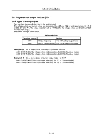
1. 5. Control Input/Output
5-8 Programmable output function (PO)
5-8-1 Types of analog outputs
As a standard, there are 2 channels for the analog output.
The voltage output and current output can be selected for AO1 and AO2 by setting parameter C14-7, 8
and EL-BIT W3, W4. The output resolution is 0 to 10V/10bit for the voltage output and 0 to 20mA/10bit
for the current output.
The default setting is shown below.
Default settings
Terminal symbol Setting
AO1 Output frequency 0 to 10V voltage output mode
AO2 Output current (Motor) 0 to 10V voltage output mode
Example 5-3) Set as shown below for voltage output mode 0 to 10V.
AO1: C14-7=1 (0 to 10V voltage output mode selection), Set W3 to 1 (voltage mode)
AO2: C14-8=1 (0 to 10V voltage output mode selection), Set W4 to 1 (voltage mode)
Example 5-4) Set as shown below for current output mode 4 to 20mA
AO1: C14-7=3 (4 to 20mA output mode selection), Set W3 to 2 (current mode)
AO2: C14-8=3 (4 to 20mA output mode selection), Set W4 to 2 (current mode)
5 – 16
2. 5. Control Input/Output
5-8-2 Setting the analog output
A following internal data can be output to AO1, AO2 terminals with parameters C13-0 and 1 as shown in
Fig. 5-8-2. Set the number corresponding to the internal data in C13-01, 1. If the gain needs to be
adjusted, set C14-0, 1 appropriately. Signed data can be output by setting the offset voltage with C14-3,
4 and setting the offset current with C14-5, 6.
Fig. 5-8-2 Analog output assignment
5 – 17
0
1
2
3
4
5
6
7
8
9
10
11
12
13
14
15
16
17
18
19
AO1
AO2
AOP1
AOP2
AOP3
AOP4
Output frequency
Setting frequency (Setting speed)
Cushion output
Output current (Motor)
Output current (Drive)
Output voltage
Drive output powe r
DC voltage
OLT monitor
(motor protection )
Heat sink temperature
Motor speed
Torque current
Excitation current
Actual motor rotation speed
Namp output
OLT monitor
(device protection)
Built-in PLC output 1
Built-in PLC output 2
Built-in PLC output 3
Built-in PLC output 4
Internal data
For future use
Terminal block
C13-0=3
C13-0=0
3. 5. Control Input/Output
5-8-3 Pulse train output
The pulse train output is one channel, and uses the terminal block output PS03. When using the pulse
train output function, PS03 cannot be used as a sequence output. Note that when this function is used,
the speed detection option I pulse division function (C50-0) cannot be used.
The settings and precautions for the control PCB used with the pulse train output function are given
below.
1) Turn the DIP switch (DS1-4) ON before turning the power ON.
2) Connect the PS03 to the device while observing the precautions for the sequence output (open
collector output).
3) Set PS03 terminal output selection to OFF fixed (C13-5=0).
4) The maximum output frequency is 6kHz (25°C). Use the falling edge.
5) Faults could occur if the DS1-4 and C13-5 settings are mistaken.
The settings for using the pulse train output function are shown below.
1) Enable the pulse train output function.
Parameter No. Name Function
C13-B Pulse train output function
=1 : Pulse train output function Valid
=2 : Pulse train output function Invalid
2) Set PS03 terminal output selection to OFF fixed (C13-5=0).
3) Select the internal data to be output as a pulse train with C13-E as shown in Fig. 5-8-3-a.
Internal data
Output frequencye
Setting frequency (Speed)
Cushion output
Motor speed
Actual motor rotation speed
C13-E
0
1
2
3
4
PSO3
Fig. 5-8-3-a Pulse train output assignments
5 – 18
4. 5. Control Input/Output
4) Refer to Fig. 5-8-3-b, and set the frequency of the pulses output with C13-C, D.
To output the absolute value of the internal data, set C13-F to 2.
10kHz
0.1Hz
0% Fmax
Internal data [%]
Outputpulsefrequency[Hz]
C13-D
C13-C
Fig. 5-8-3-b
(Note) The output pulse frequency range is 0.1 to 10kHz.
A pulse less than 0.1Hz cannot be output even during reverse run.
When outputting from the sequence output PS03, only a pulse frequency of 6kHz or less (25°C,
maximum current = 50mA) can be output. Set C13-C, D to 6000Hz or less.
Parameter
No.
Name Function
C13-F
Output parameter
absolute value
operation selection
=1 : Internal data absolute value operation function Valid
=2 : Internal data absolute value operation function Invalid
5 – 19
5. 5. Control Input/Output
5-9 Selecting the setting data
5-9-1 Speed setting
(1) Speed setting selection
The ten types of speed setting inputs shown below can be used.
One of the ten types of inputs can be selected by setting a parameter or with the sequence input.
Setting
input point
Setting data Explanation
Analog
Analog speed setting 1
Analog speed setting 2
Analog speed setting 3
This is a setting value issued with an analog input.
Serial Serial speed setting
This is a setting value issued from the host computer with serial
transmission. Setting is possible with the following serial
transmission.
• Communication interface option (Type: U30V24SL0/1/2/3/4)
• Standard serial transmission •Modbus communication
Parallel Parallel speed setting
This is a setting value issued from the host sequencer with
parallel transmission. A PC interface option (type: U30V24PI0) is
required.
Sequence Pulse train speed setting This is the setting value issued from the pulse train input.
Panel
Panel speed setting This is the setting value issued from the parameter (A00-0, 2).
Panel jogging setting This is a setting value issued from the parameter (A00-1, 3).
Traverse pattern operation
This is the traverse pattern operation setting value with parameter
(B45-0 to 6).
Pattern operation
This is the pattern operation setting value with parameter (B50-0
to B59-3).
(2) Speed setting selection sequence
The relation of the speed setting and changeover sequence is as shown below.
Speed
setting
value
=4
AX+B
≠ 4
B40- 0
on
PROG
on
PLS_IN
on
CFS
on JOG
on
B40- 0
=3
≠ 3
C30- 0f 0
=1, =2
=3, =4, =5
RF0
0
on
LCL
C02- 0
=5
=4
=3
=2
=1
Changeover with
sequence input
Ratio interlock
operation *3
AFS3
on
on
on
AFS2
AFS1
AX+B
of f
of f
of f
of f
of f
of f
of f
of f
of f
Ratio interlock bias
setting (C07-3)
Analog speed
setting 3 (C07-2)
Analog speed
setting 2 (C07-1)
Analog speed
setting 1 (C07-0)
Serial/parallel
speed setting
Panel speed setting
(A00-0, A00-2)
Traverse pattern run
speed setting
Program speed
setting
Panel jogging speed
setting (A00-1, A00-3)
Pattern run speed setting
(B50-1 to B59-1)
Pulse train input speed
setting
Ratio interlock
operation *2
Ratio interlock
operation *1
Ratio interlock
operation *4
Ratio interlock
operation *5
AX+B
AX+B
AX+B
+
+
+
+
+
Changeover with
parameter setting
*1 A:B06-0, B:B06-1(V/f) or B06-2(VEC,PM)
*2 A:B06-3, B:B06-4(V/f) or B06-5(VEC,PM)
*3 A:B06-6, B:B06-7(V/f) or B:B06-8(VEC,PM)
*4 A:B06-9, B:B06-A(V/f) or B:B06-B(VEC,PM)
*5 A:B06-C, B:B06-D(V/f) or B:B06-E(VEC,PM)
Fig. 5-9-1 Speed setting selection
5 – 20
6. 5. Control Input/Output
5-9-2 Torque setting
(1) Torque setting selection
The following four types of torque setting inputs can be used.
One of the four types of inputs can be selected by setting a parameter or with the sequence input.
Setting
input point
Setting data Explanation
Analog Analog torque setting This is a setting value issued from the analog input.
Serial Serial torque setting
This is a setting value issued from the host computer with
serial transmission. Setting is possible with the following
serial transmission.
• Communication interface option (Type:
U30V24SL0/1/2/3/4)
• Standard serial transmission •Modbus communication
Sequence
Pulse train Torque
setting
This is the setting value issued from the pulse train input.
Panel Panel torque setting This is a setting value issued from the parameter (B13-0).
(2) Torque setting selection sequence
The relation of the torque setting and changeover sequence is as shown below.
on
off
LCLoff
on
CFS
on
PLS_IN
C02-2
=1
=2
=3
=4
: Changeover with sequence input
: Changeover with parameter setting
=5
-1
Forward run
Reverse run
Torque
settingAnalog torque
setting (C07-6)
Serial torque
setting
Panel torque
setting (B13-0)
Pulse train input
torque setting
off
Fig. 5-9-2 Torque setting selection
5 – 21
7. 5. Control Input/Output
5-9-3 Torque bias 1 setting
(1) Torque bias 1 setting selection
The following three types of torque bias 1 setting inputs can be used.
One of the three types of inputs can be selected by setting a parameter or with the sequence input.
Setting
input point
Setting data Explanation
Analog
Analog torque bias 1
setting
This is a setting value issued from the analog input.
Serial
Serial torque bias 1
setting
This is a setting value issued from the host computer with
serial transmission. Setting is possible with the following
serial transmission.
• Communication interface option (Type:
U30V24SL0/1/2/3/4)
• Standard serial transmission •Modbus communication
Panel
Panel torque bias 1
setting
This is a setting value issued from the parameter (B13-2).
(2) Torque bias 1 setting selection sequence
The relation of the torque bias 1 setting and changeover sequence is as shown below.
: Changeover with
sequence input
: Changeover with
parameter setting
TRQB1
on
0
off
Torque
bias 1
setting
Analog torque
bias 1 setting
(C07-9)
Serial torque
bias 1 setting
Panel torque
bias 1 setting
(B13-2)
on
off
CFS
=1
=2
=3
=4
on
off
C02-4
LCL
Fig. 5-9-3 Torque bias 1 setting selection
5-9-4 Torque limiter setting
(1) Torque limiter reduction setting selection
The torque limiter can be set independently for the drive side and regeneration side in the ASR
mode and ACR mode. The setting parameters are as shown below. If the emergency stop sequence
is valid, the regeneration side limiter value will become the emergency stop limiter value.
A10-3 : ASR drive torque limiter setting
A10-4 : ASR regenerative torque limiter setting
A10-5 : Emergency stop regenerative torque limiter setting
A11-2 : ACR drive torque limiter setting
A11-3 : ACR regenerative torque limiter setting
For each limiter input, the limiter value can be reduced by external or internal settings. The final
limiter value is the results of multiplying the above panel setting values with the reduction ratio.
5 – 22
8. 5. Control Input/Output
(1-1) External reduction setting
The limiter reduction setting input from an external source includes the following two types
independently for the drive and regeneration.
One of the two types of inputs can be selected by setting a parameter or with the sequence input.
Setting
input point
Setting data Explanation
Analog
Analog drive torque limiter
reduction setting
This is a setting value issued with an analog input.
The drive torque limit (A10-3 or A11-2) is multiplied using 0V
to +10V as 0 to 100%, and the limit value is reduced.
This function is valid when the drive limiter changeover (LIM1)
is turned ON with the sequence input.
Analog regenerative torque
limiter reduction setting
This is a setting value issued with an analog input.
The regenerative torque limit (A10-4, A10-5 or A11-3) is
multiplied using 0V to +10V as 0 to 100%, and the limit value
is reduced.
This function is valid when the regenerative limiter changeover
(LIM2) is turned ON with the sequence input.
Serial
Serial driver torque limiter
reduction setting
This is a setting value issued from the host computer with
serial transmission. Setting is possible with the following serial
transmission.
• Communication interface option (Type: U30V24SL0/1/2/3/4)
• Standard serial transmission •Modbus communication
The data is set in the range of 0 to 100%, is multiplied with the
drive torque limiter value (A10-3, A11-2), and the limiter value
is reduced. This function is valid when the drive limiter
changeover (LIM1) is turned ON with the sequence input.
Serial regenerative torque
limiter reduction setting
This is a setting value issued from the host computer with
serial transmission. Setting is possible with the following serial
transmission.
• Communication interface option (Type: U30V24SL0/1/2/3/4)
• Standard serial transmission •Modbus communication
The data is set in the range of 0 to 100%, is multiplied with the
regenerative torque limiter value (A10-4, A10-5, A11-3), and
the limiter value is reduced.
This function is valid when the regenerative limiter changeover
(LIM2) is turned ON with the sequence input.
(1-2) Internal reduction setting
When the double rating speed ratio setting (B13-4) is changed, the torque limiter reduction
pattern will be generated as shown below, and will be multiplied with the drive torque limiter
value (A10-3 or A11-2) and regenerative torque limiter value (A10-4, A10-5, A11-3).
NBASE
Speed (min
–1
)
Reductionratio(%)
KDBL (%) × NBASE (min
–1
)
NFB (min
–1
)
5 – 23
KDBL : B13-4
Double rating speed ratio (%)
NFB : Speed detection (min–1
)
NBASE : Base speed (min–1
)
NDBL : NBASE × KDBL (min–1
)
9. 5. Control Input/Output
(2) Torque limiter setting selection sequence
The relation of the torque limiter setting and changeover sequence is as shown below.
100%
KDBL(%)
off
on
CFS
=1
=2
=3,4
C02-6
When NFB < NDBL
When NDBL ≤ NFB ≤ NBASE
When NBASE < NFB
: Changeover with
sequence input
: Changeover with
parameter setting
Analog drive torque
limiter reduction
setting (C07-7)
Serial drive torque
limiter reduction
setting
ACR drive torque
limiter (A11-2)
ASR drive torque
limiter (A10-3)
KDBL (%) × NBASE (min–1
)
NFB (min–1
)
Drive side
torque
limiter
LIM1
off
on
on
off
ACR
Fig. 5-9-4-a Drive torque limiter setting selection
When NFB < NDBL
When NDBL ≤ NFB ≤ NBASE
When NBASE < NFB
: Changeover with
sequence input
: Changeover with
parameter setting
Analog regenerative torque
limiter
reduction setting
(C07-8)
Serial regenerative torque
limiter
reduction setting
Emergency stop regenerative
torque limiter (A10-5)
ACR regenerative torque limiter
(A11-3)
ASR regenerative torque limiter
(A10-4)
KDBL (%)
KDBL (%)×NBASE (min–1
)
NFB (min–1
)
100%
Regenerative
side torque
limiter
on
off
CFS
=1
=2
=3, 4
C02-6
off
on
ACR off
on LIM2
off
on
EMS
Fig. 5-9-4-b Regenerative torque limiter setting selection
5 – 24
KDBL : B13-4
Double rating speed ratio (%)
NFB : Speed detection (min–1
)
NBASE : Base speed (min–1
)
NDBL : NBASE×KDBL (min–1
)
10. 5. Control Input/Output
5-9-5 Torque ratio 1 setting
(1) Torque ratio 1 setting selection
The following two types of torque ratio 1 setting inputs can be used.
One of the two types of inputs can be selected by setting a parameter or with the sequence input.
Setting
input point
Setting data Explanation
Serial Torque ratio 1 setting
This is a setting value issued from the host computer
with serial transmission.
Setting is possible with the Communication interface
option (Type: U30V24SL0/1/2/3/4).
Panel
Panel torque ratio 1
setting
This is a setting value issued from the parameter (B13-1).
(2) Torque ratio 1 setting selection sequence
The relation of the torque ratio 1 setting and changeover sequence is as shown below.
Serial torque ratio
1 setting
Panel torque ratio 1
setting (B13-1)
1.000
: Changeover with sequence input
: Changeover with parameter setting
Torque ratio 1 setting
off
on
Mounted
Not
mounted
Option
CFS
=2
=3
=4
C02-3
on
off
LCL
Fig. 5-9-5 Torque ratio 1 setting selection
5 – 25
11. 5. Control Input/Output
5-9-6 Torque ratio 2, torque bias 2 setting
(1) Torque ratio 2 setting selection
The following two types of torque ratio 2 setting inputs can be used.
One of the two types of inputs can be selected by setting a parameter or with the sequence input.
Setting
input point
Setting data Explanation
Serial Torque ratio 2 setting
This is a setting value issued from the host computer
with serial transmission.
Setting is possible with the Communication interface
option (Type: U30V24SL0/1/2/3/4).
Panel
Panel torque ratio 2
setting
This is a setting value issued from the parameter (B13-3).
(2) Torque ratio 2 setting selection sequence
The relation of the torque ratio 2 setting and changeover sequence is as shown below.
Serial torque ratio
2 setting
: Changeover with sequence input
: Changeover with parameter setting
Torque ratio 2
setting
0
0
off
on
Mounted
Not
mounted
Option
CFS
=2
=3
=4
C02-5
on
off
LCL
off
on
TRQB2Panel torque ratio 2
setting (B13-3)
Serial torque setting Torque bias 2
setting
Fig. 5-9-6 Torque ratio 2 setting selection
5 – 26
12. 5. Control Input/Output
5-9-7 Machine time constant setting
(1) Machine time constant setting
The following three types of machine time constant setting inputs can be used.
One of the three types of inputs can be selected by setting a parameter or with the sequence input.
Setting
input point
Setting data Explanation
Serial Machine time constant
This is a setting value issued from the host computer
with serial transmission.
Setting is possible with the Communication interface
option (Type: U30V24SL0/1/2/3/4).
Panel
Panel machine time
constant −1
This is a setting value issued from the parameter (A10-1).
Panel machine time
constant −2
This is a setting value issued from the parameter (B15-0).
(2) Machine time constant setting and changeover sequence
The relation of the machine time constant setting and changeover sequence is as shown below.
: Changeover with sequence input
: Changeover with parameter setting
Serial machine time
constant setting
Panel machine time
constant 1 setting
(A10-1)
Panel machine time
constant 2 setting
(B15-0)
Machine time
constant setting
off
on
Mounted
Not
mounted
Option
CFS
=2
=3
=4
C02-8
on
off
LCL
on
off
MCH
Fig. 5-9-7 Machine time constant setting selection
5 – 27
13. 5. Control Input/Output
5-9-8 ASR response setting
(1) ASR response setting selection
The following two types of ASR response setting inputs can be used.
One of the two types of inputs can be selected by setting a parameter or with the sequence input.
Setting
input point
Setting data Explanation
Serial ASR response setting
This is a setting value issued from the host computer
with serial transmission.
Setting is possible with the Communication interface
option (Type: U30V24SL0/1/2/3/4).
Panel
Panel ASR response
setting
This is a setting value issued from the parameter (A10-0).
(2) ASR response setting and changeover sequence
The relation of the ASR response setting and changeover sequence is as shown below.
: Changeover with sequence
input
: Changeover with parameter
setting
Serial ASR response
setting
Panel ASR response
setting (A10-0)
ASR response
setting
off
on
Mounted
Not
mounted
Option
CFS
=2
=3
=4
C02-7
on
off
LCL
Fig. 5-9-8 ASR response setting selection
5 – 28