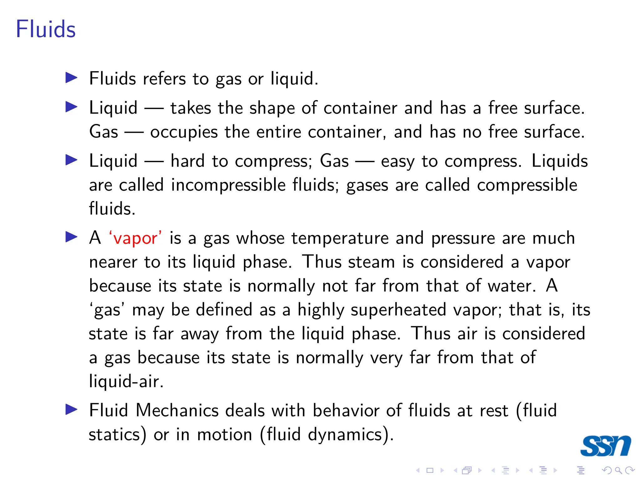
1) Fluid mechanics deals with fluids at rest (fluid statics) or in motion (fluid dynamics). It describes the behavior of liquids and gases.
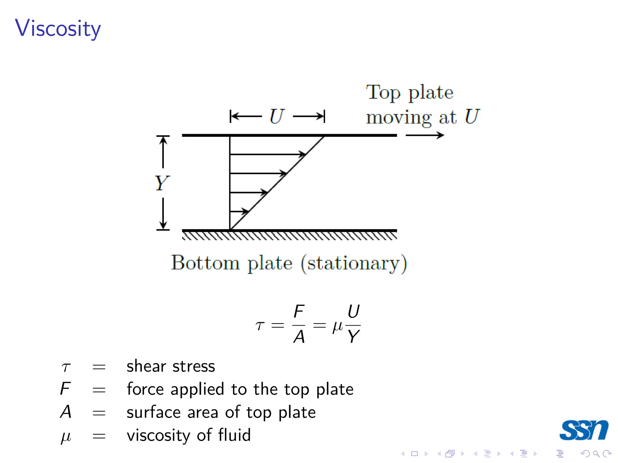
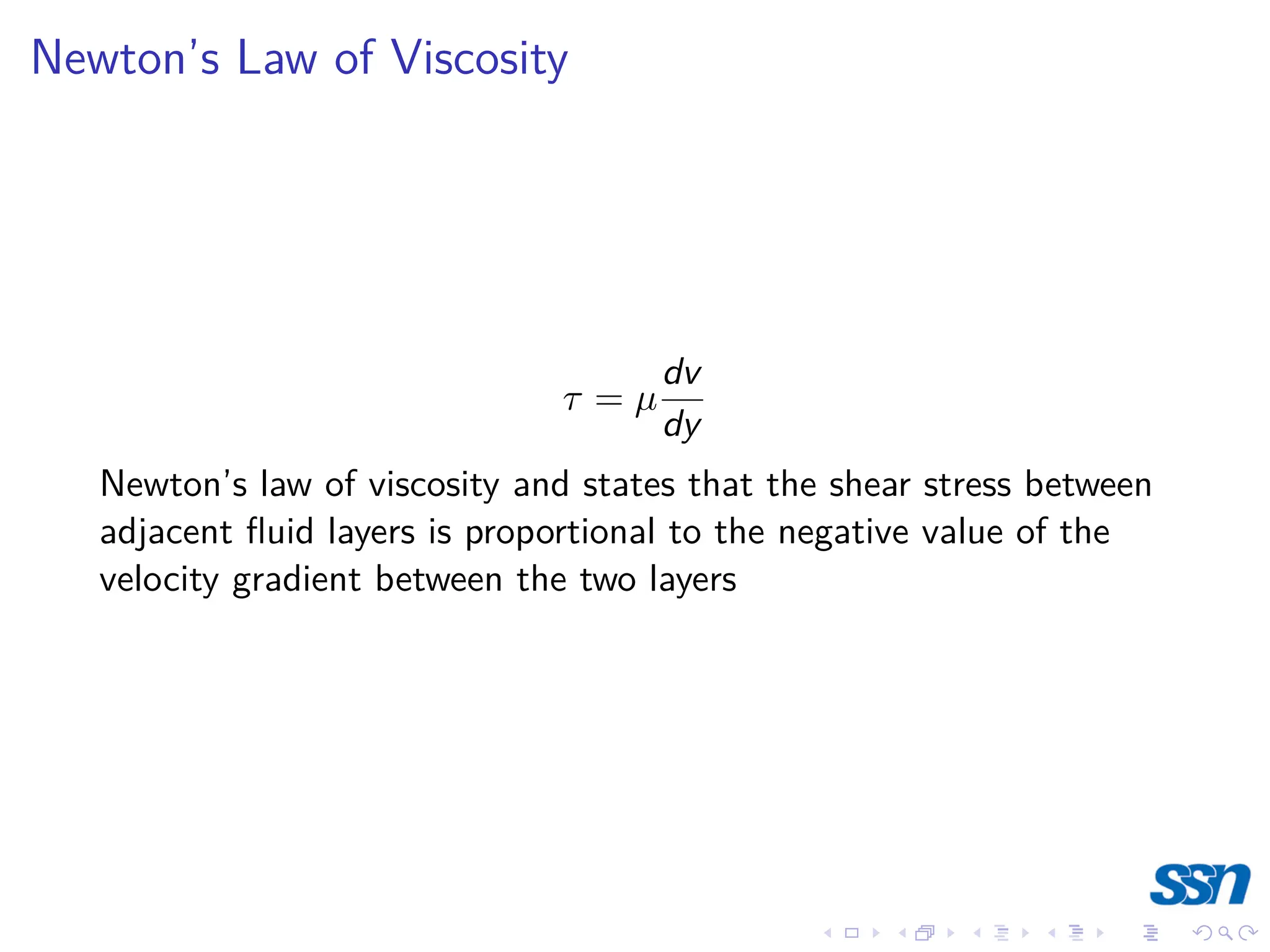
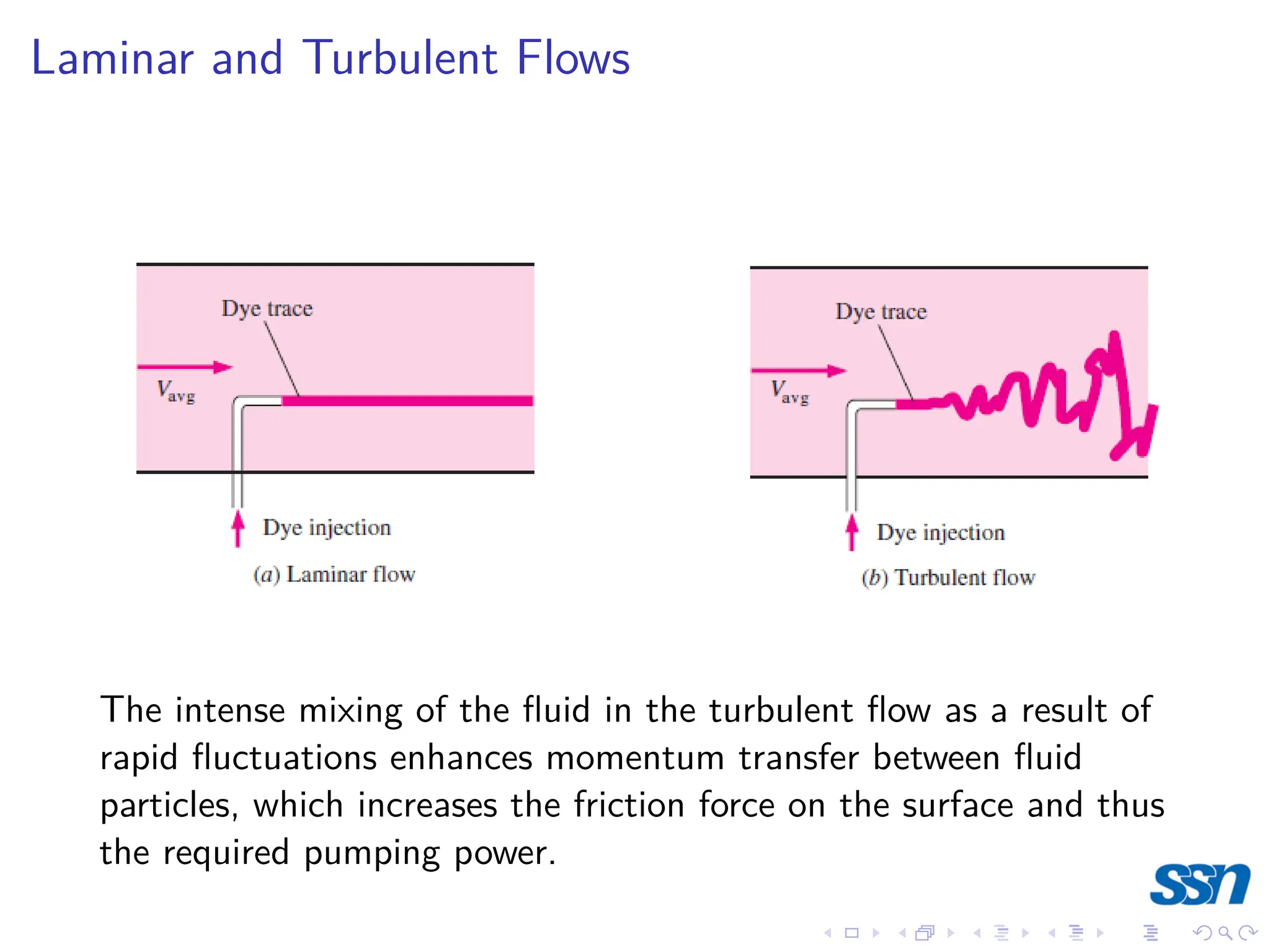
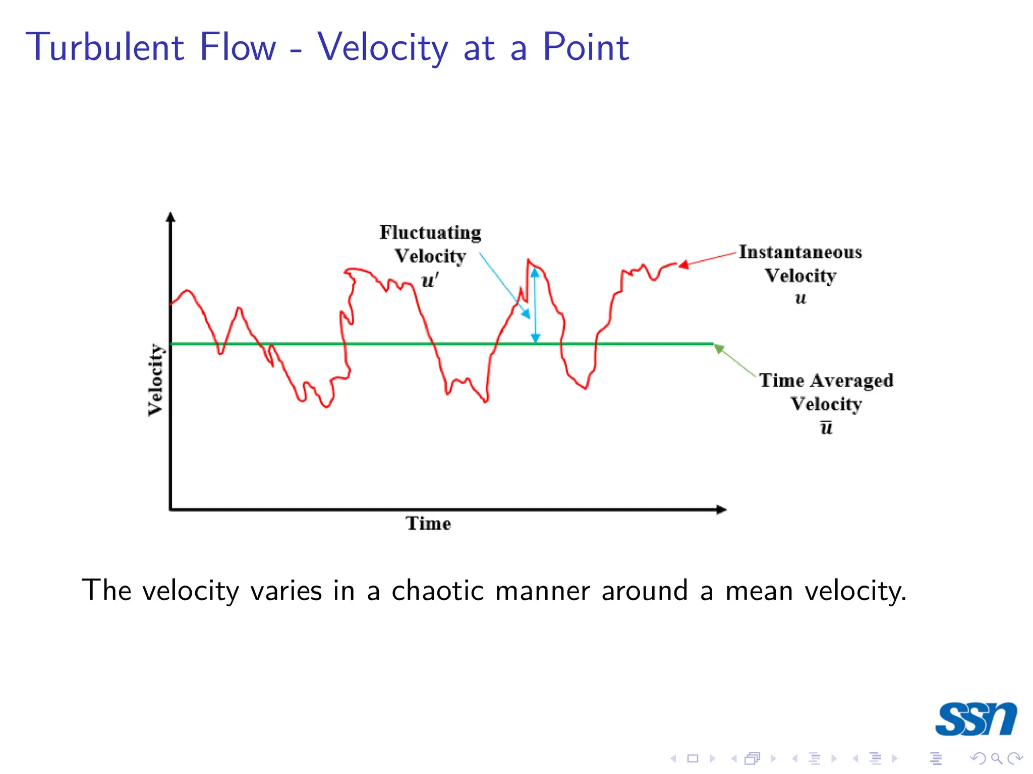
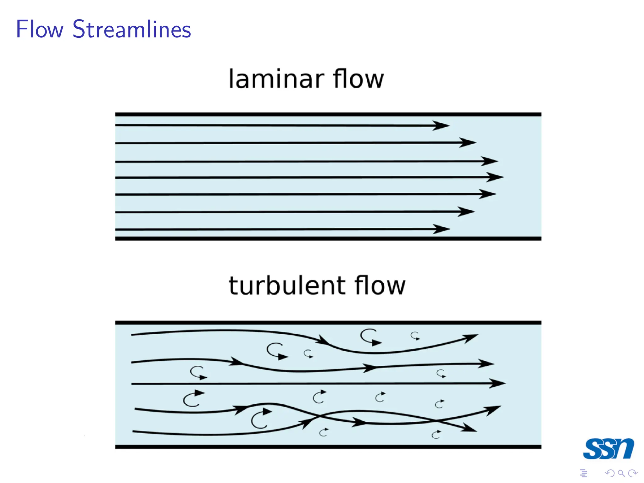
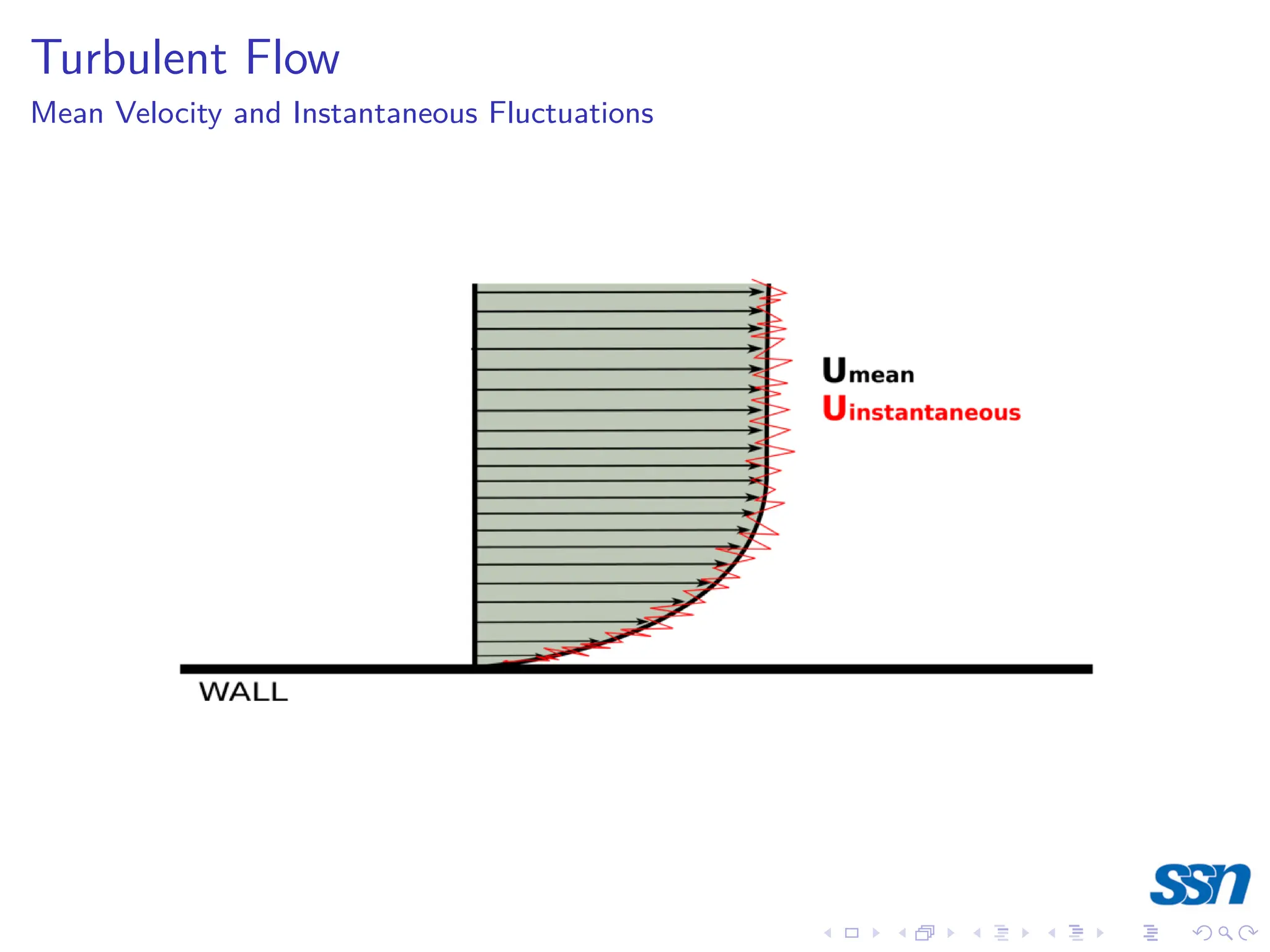
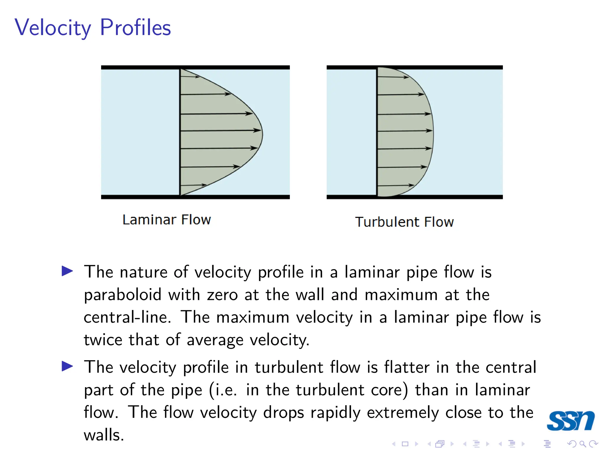
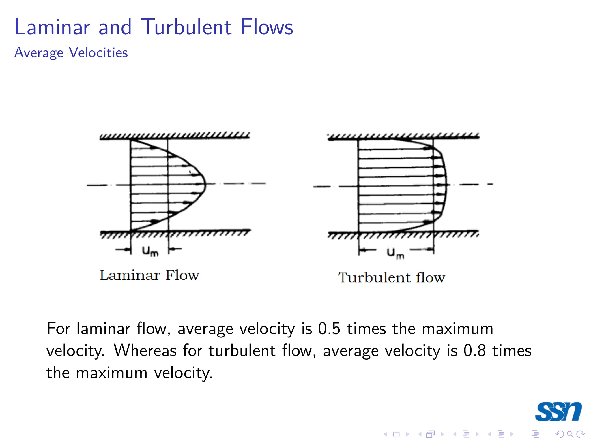
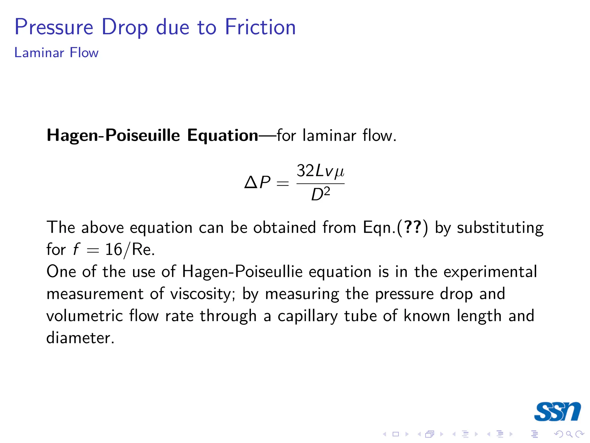
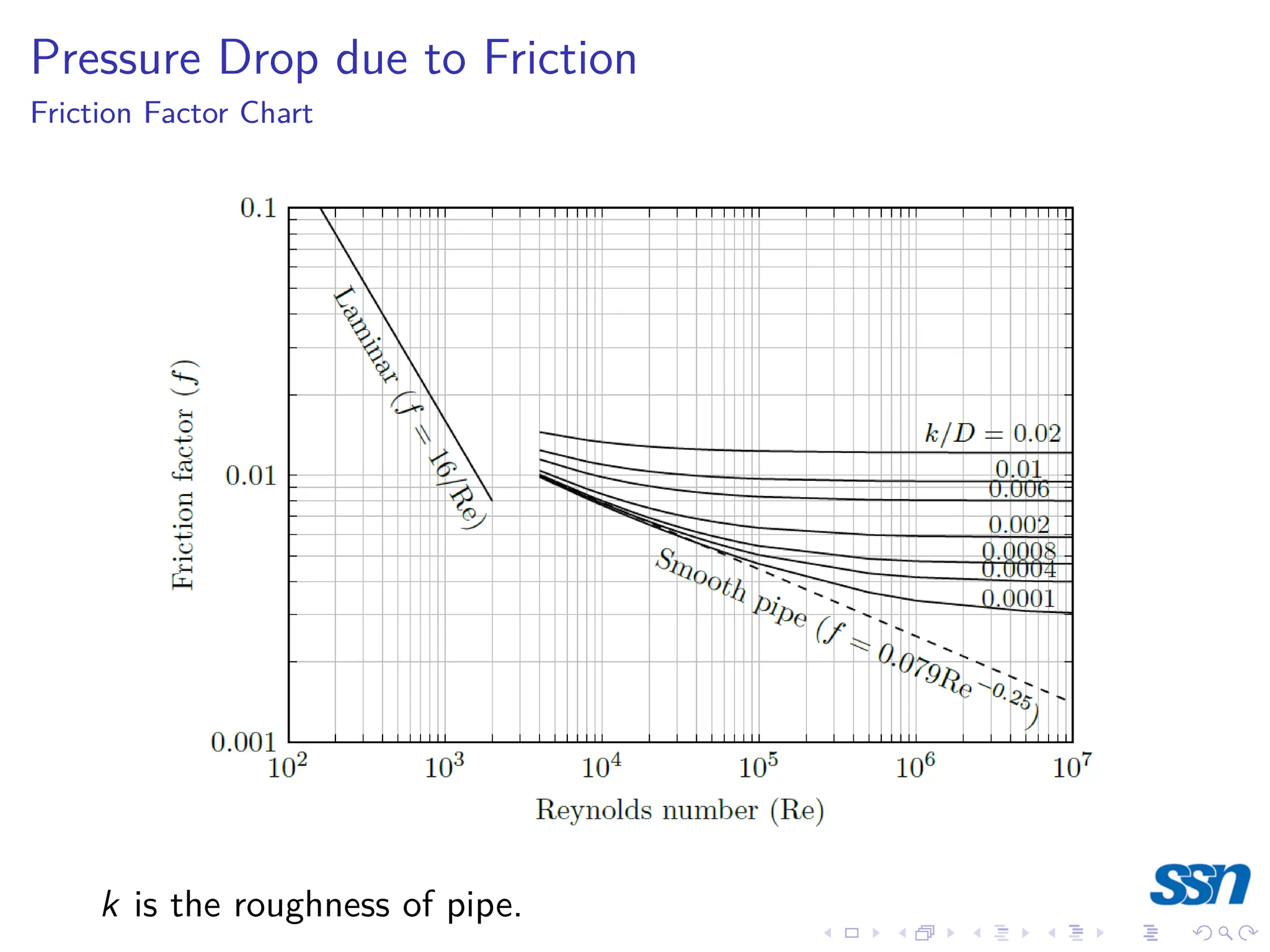
2) Viscosity is a measure of a fluid's resistance to flow. It depends on factors like temperature and pressure. Laminar flow occurs at low velocities while turbulent flow occurs at higher velocities.
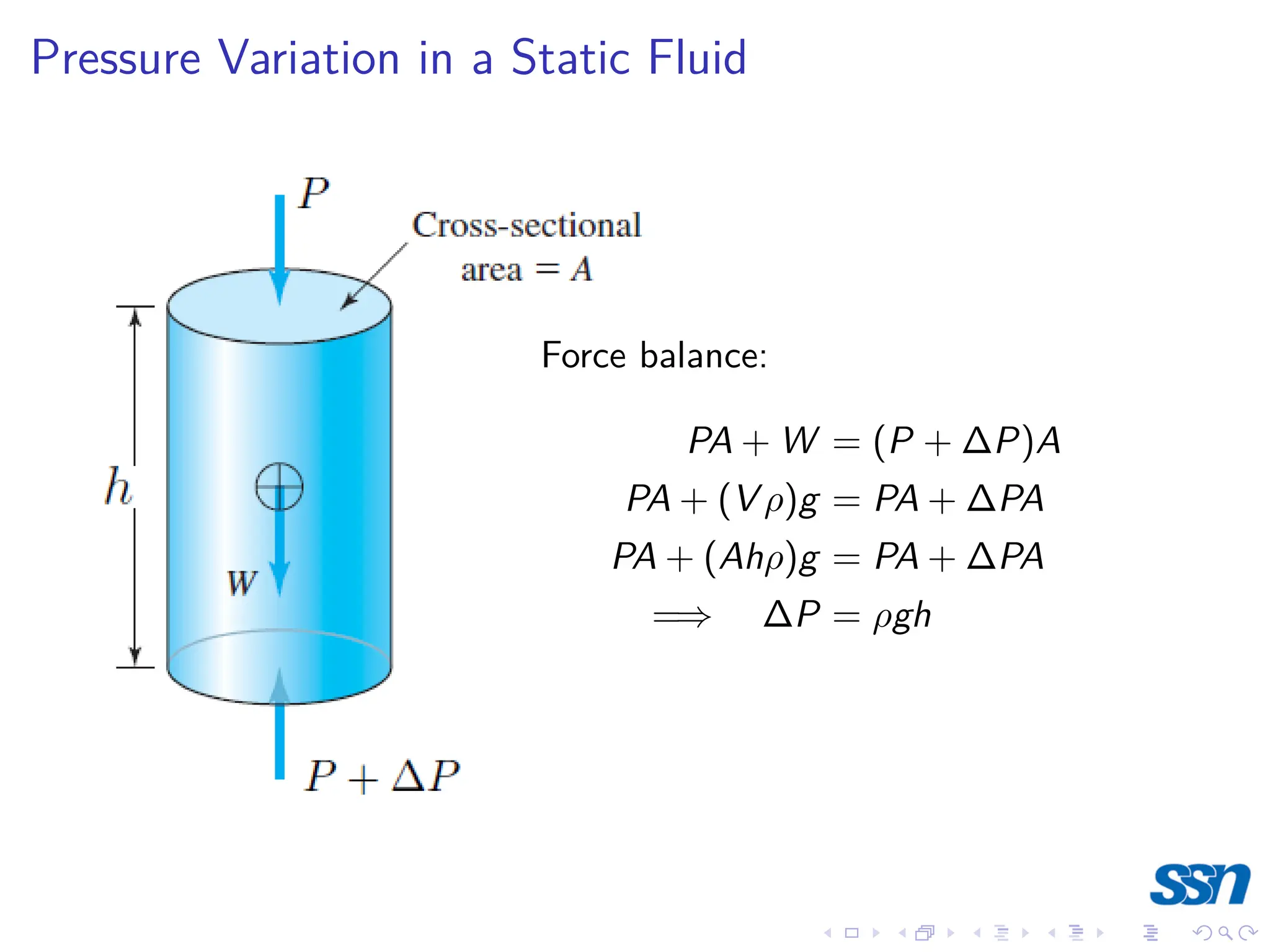
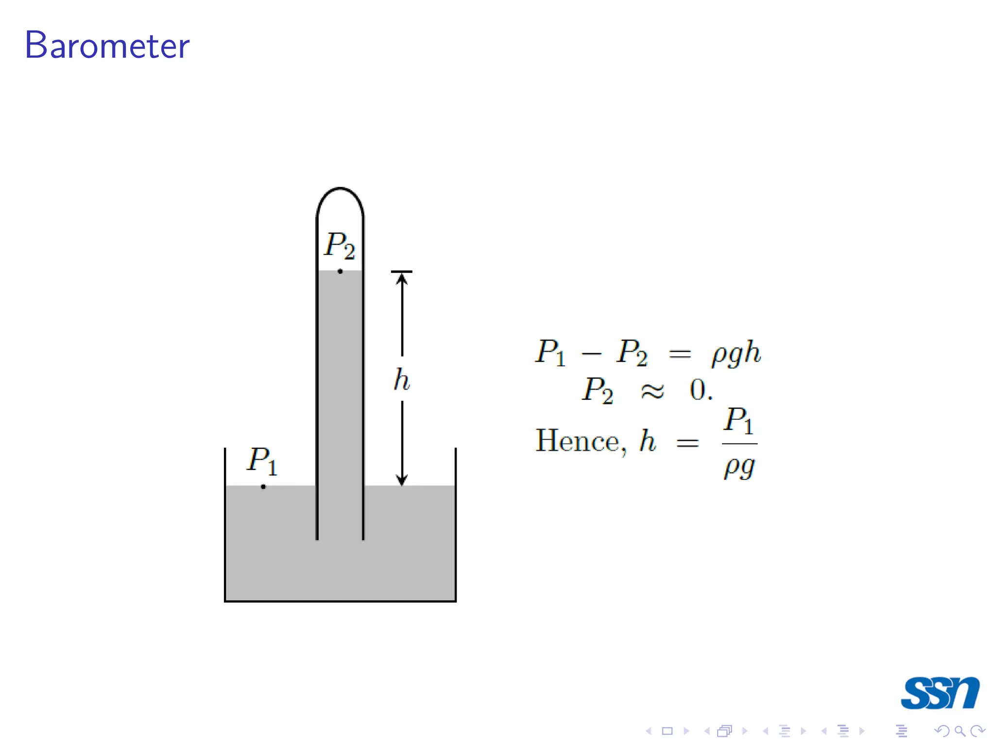
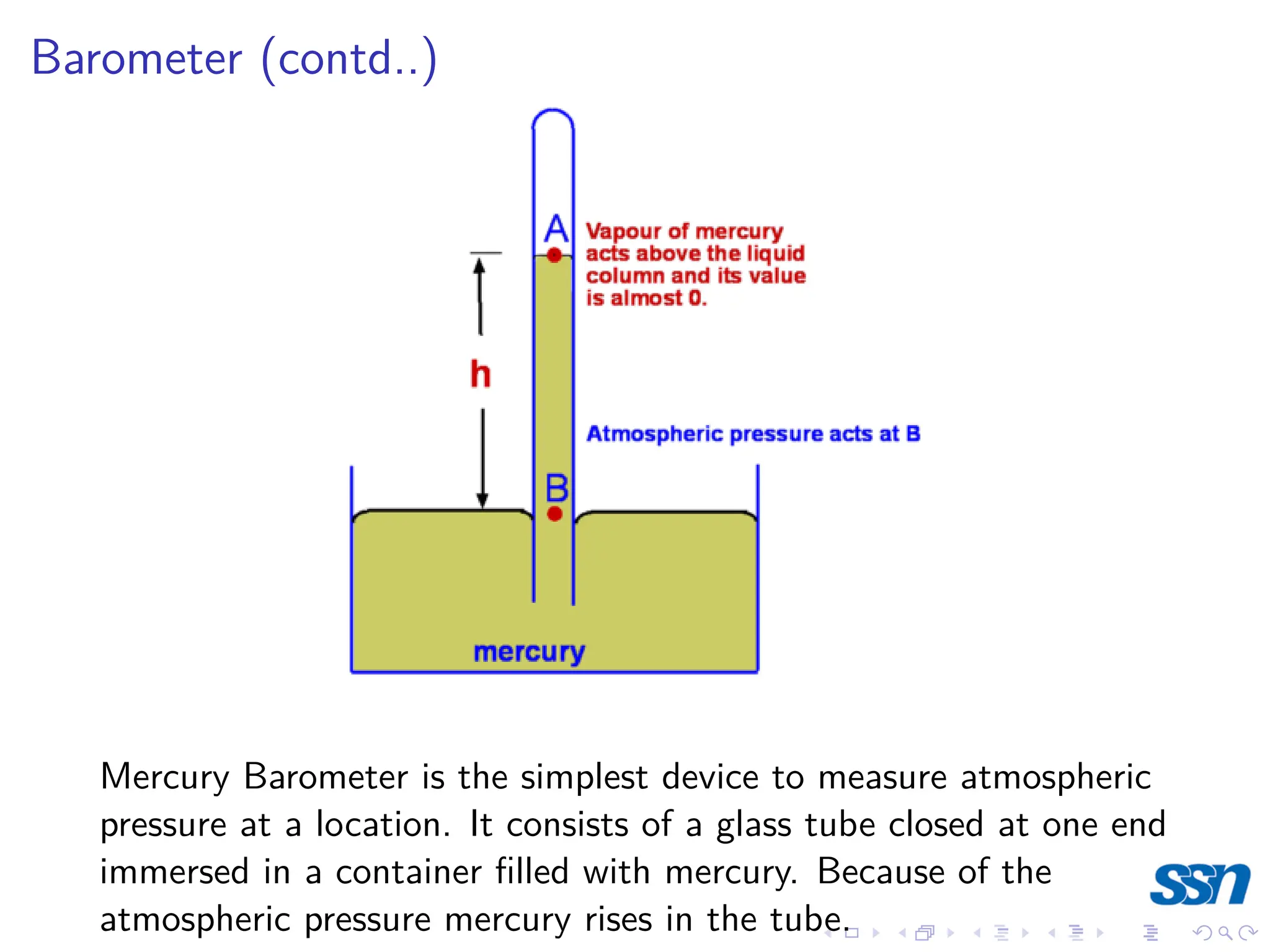
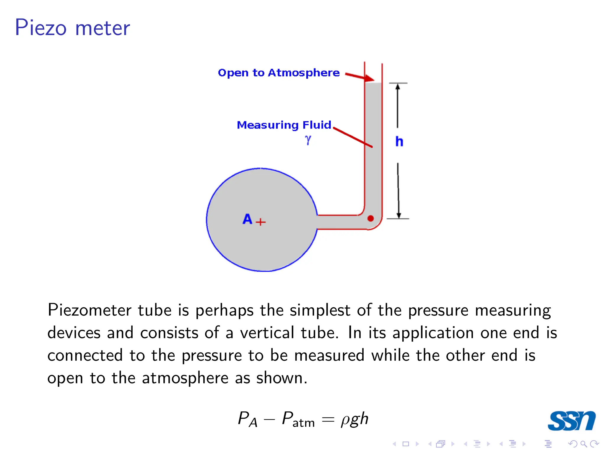
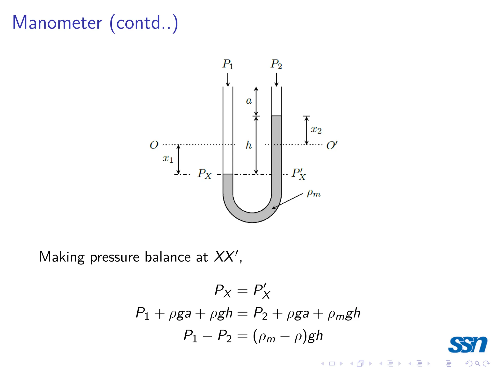
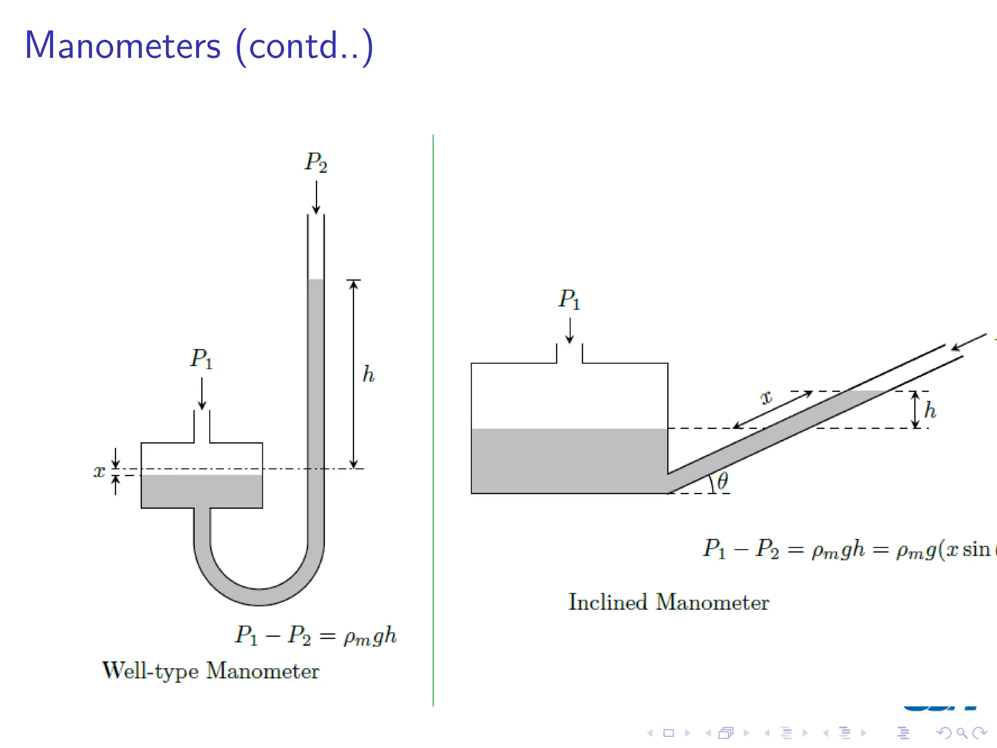
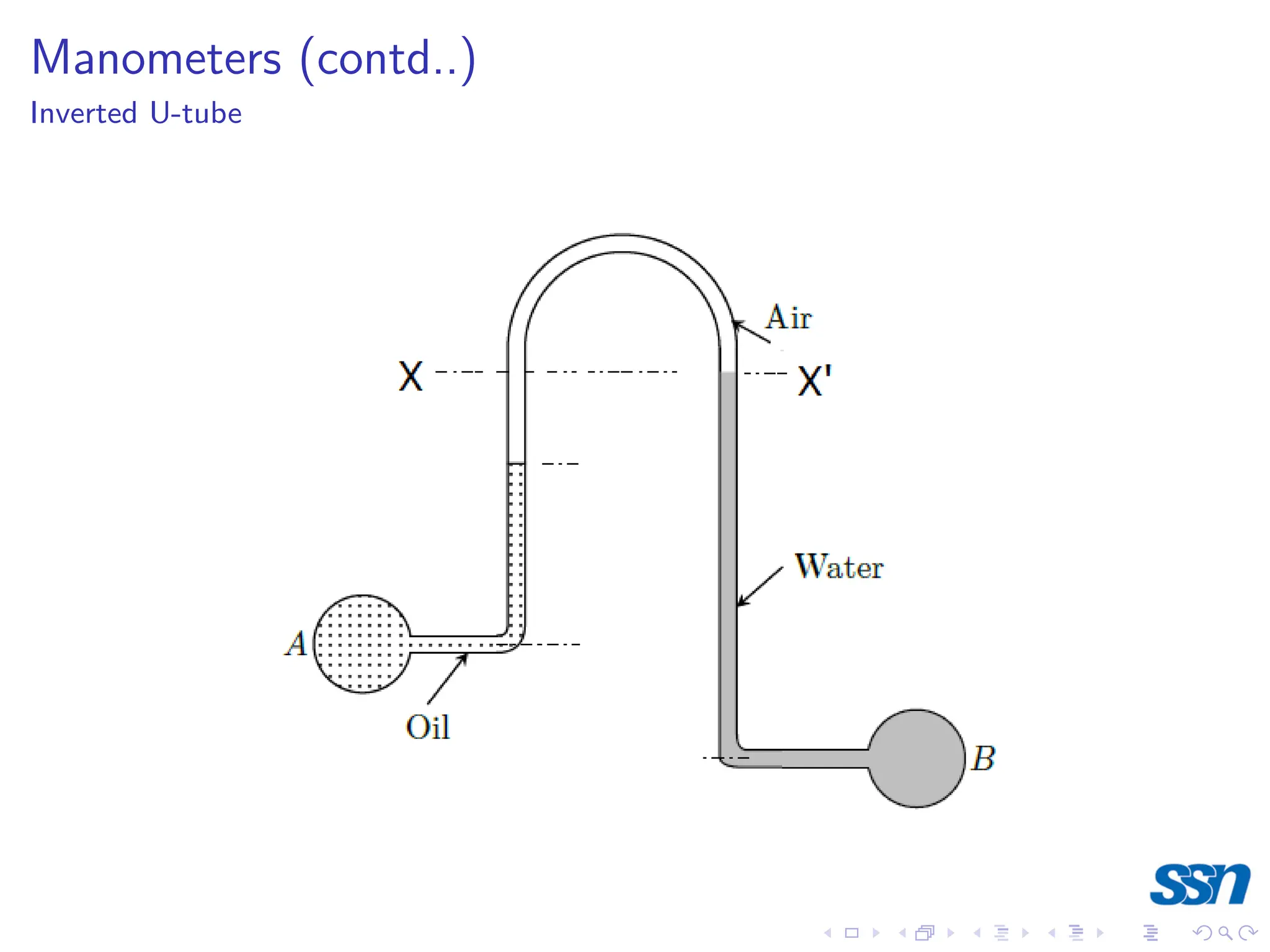
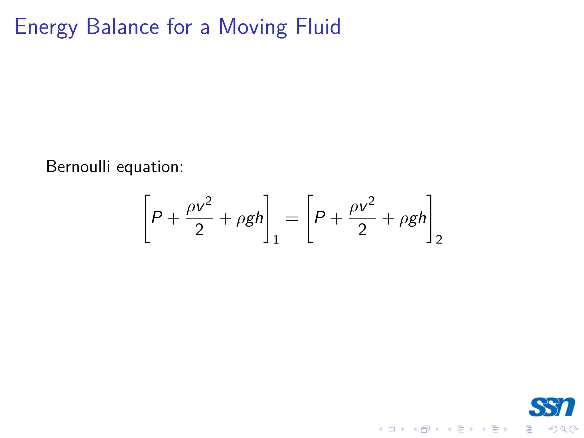
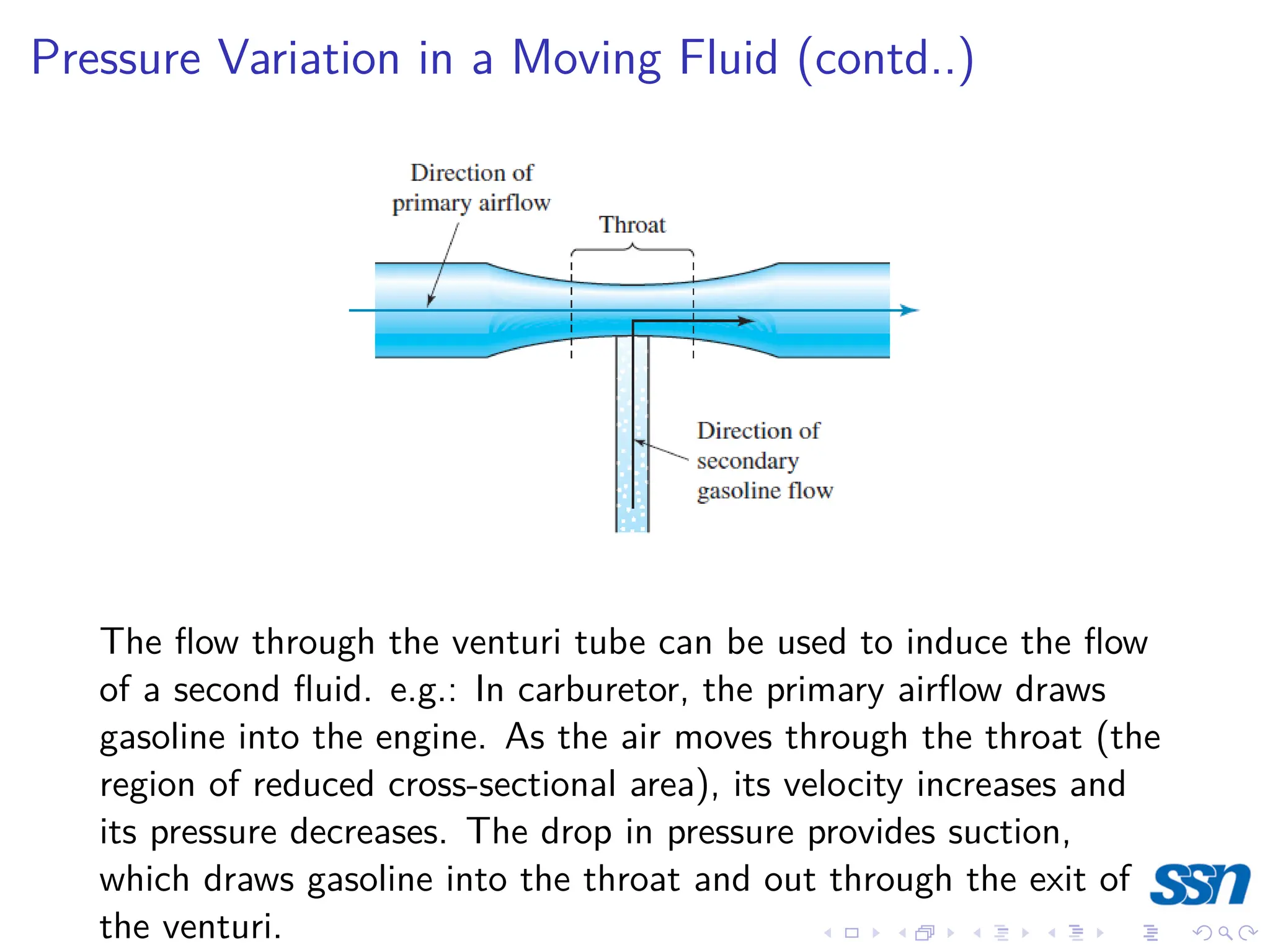
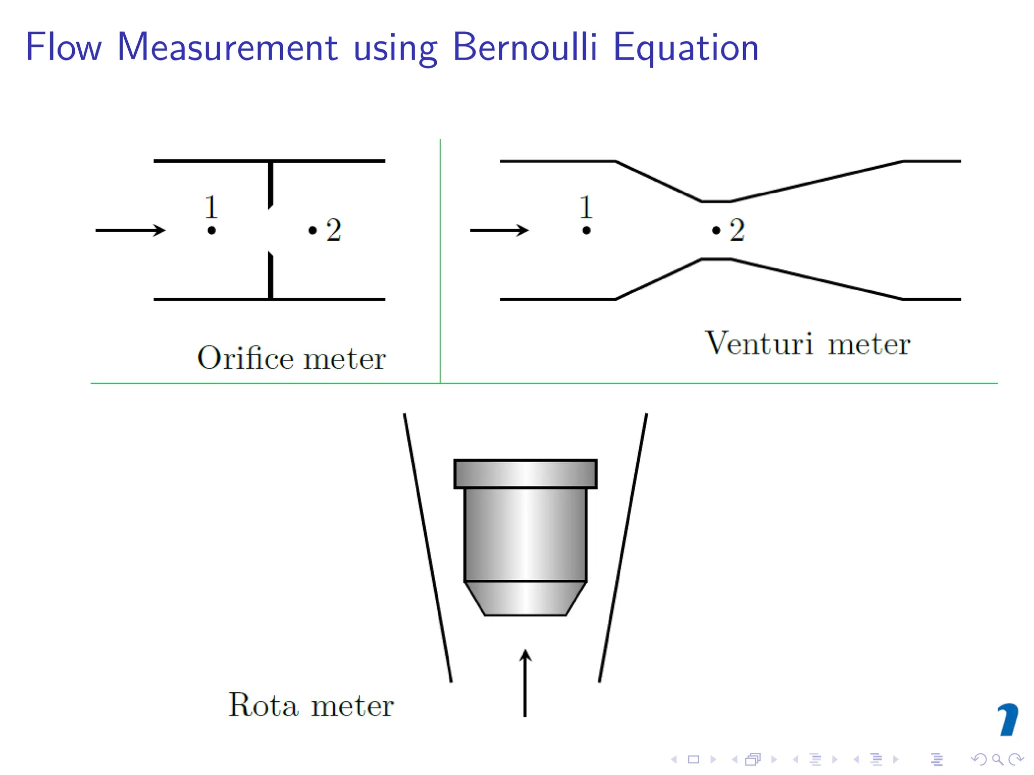
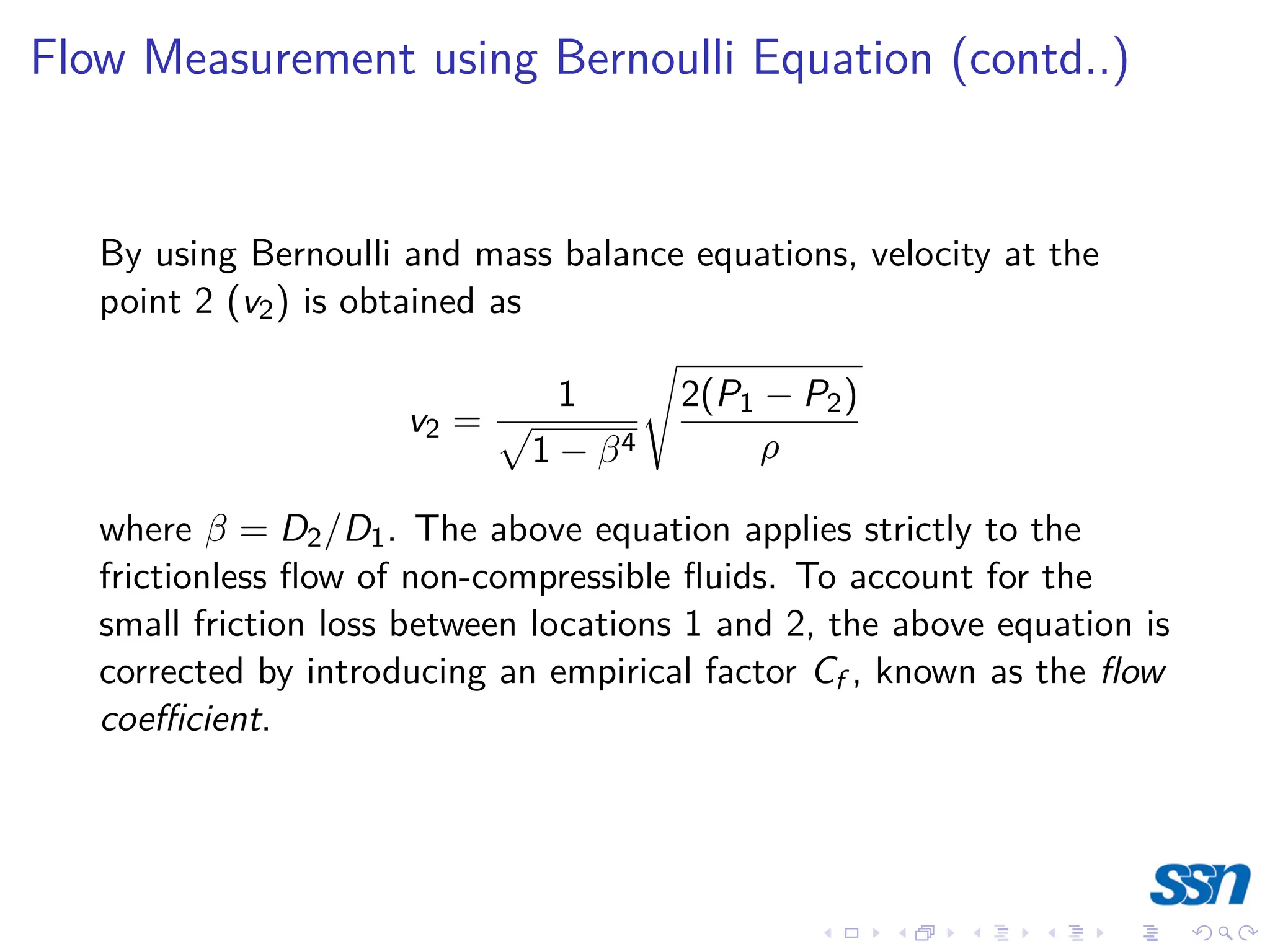
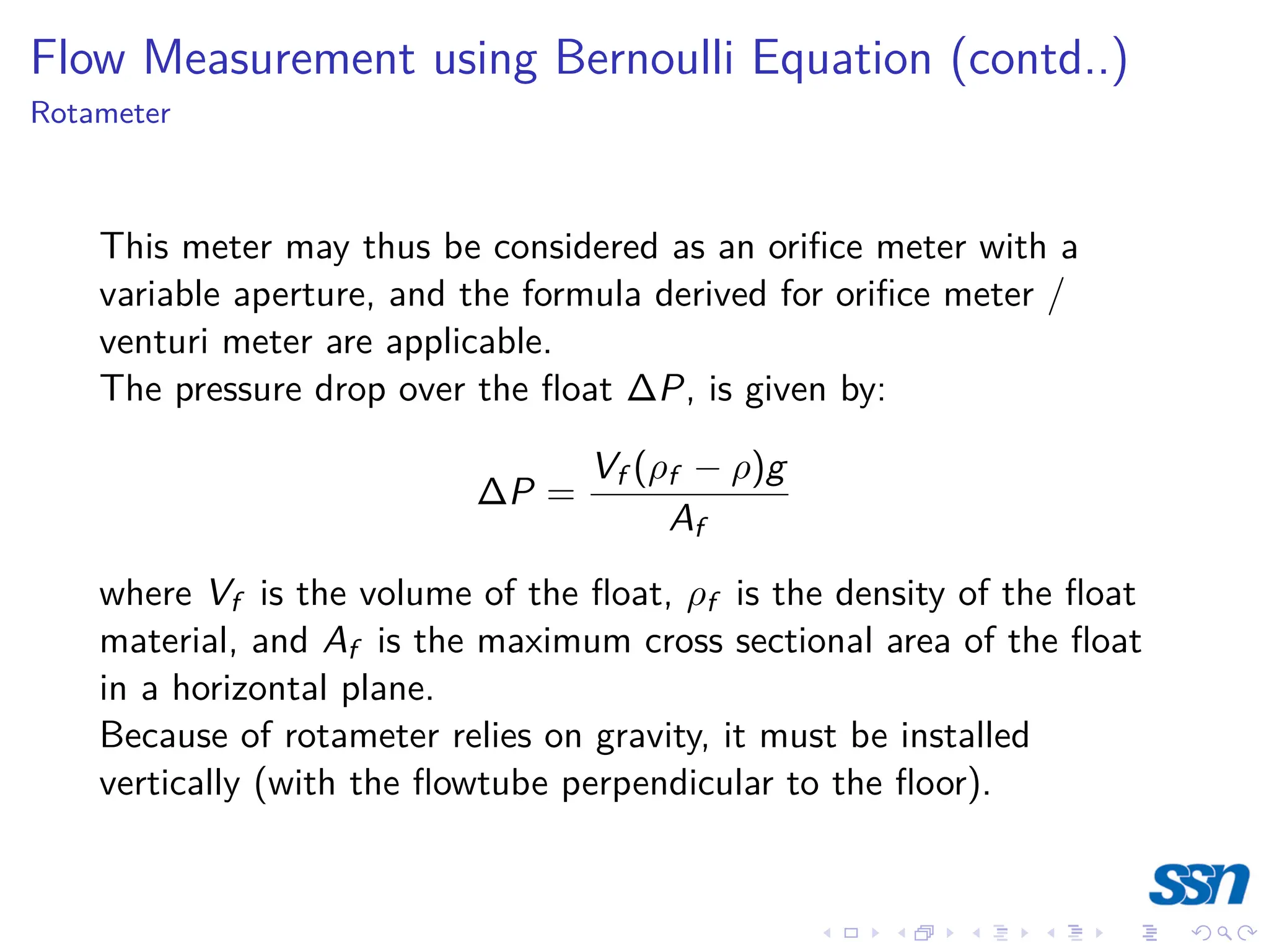
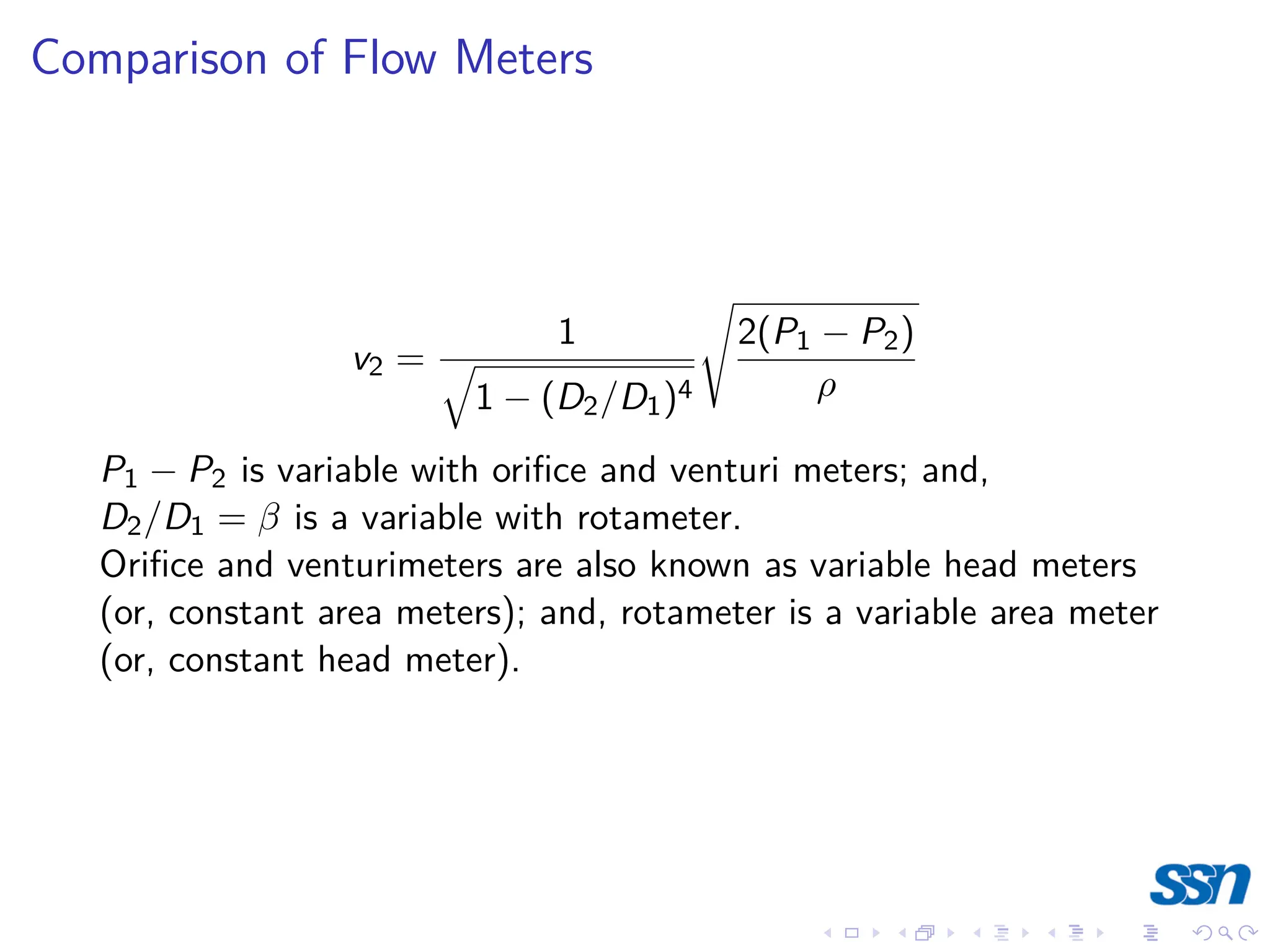
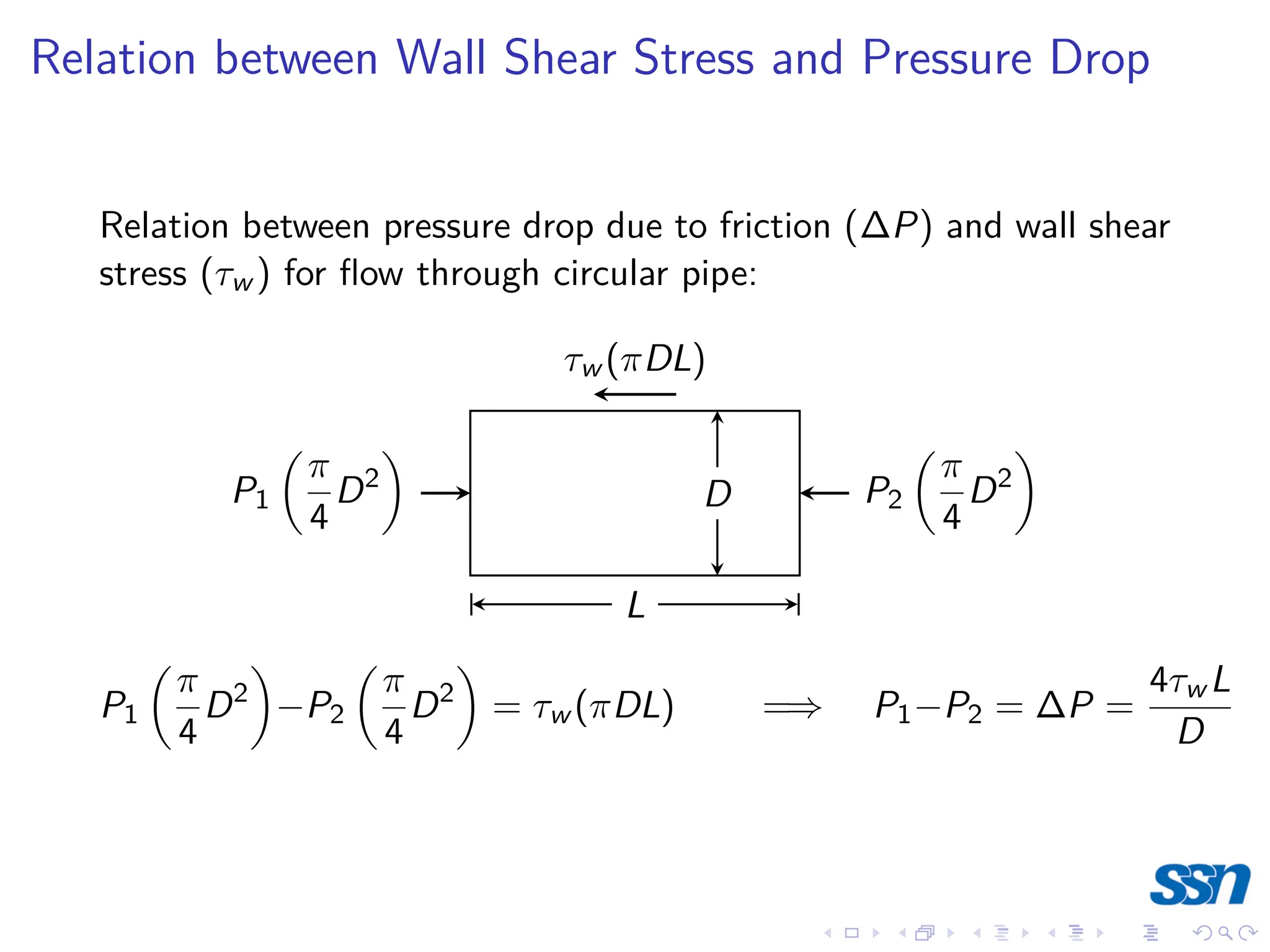
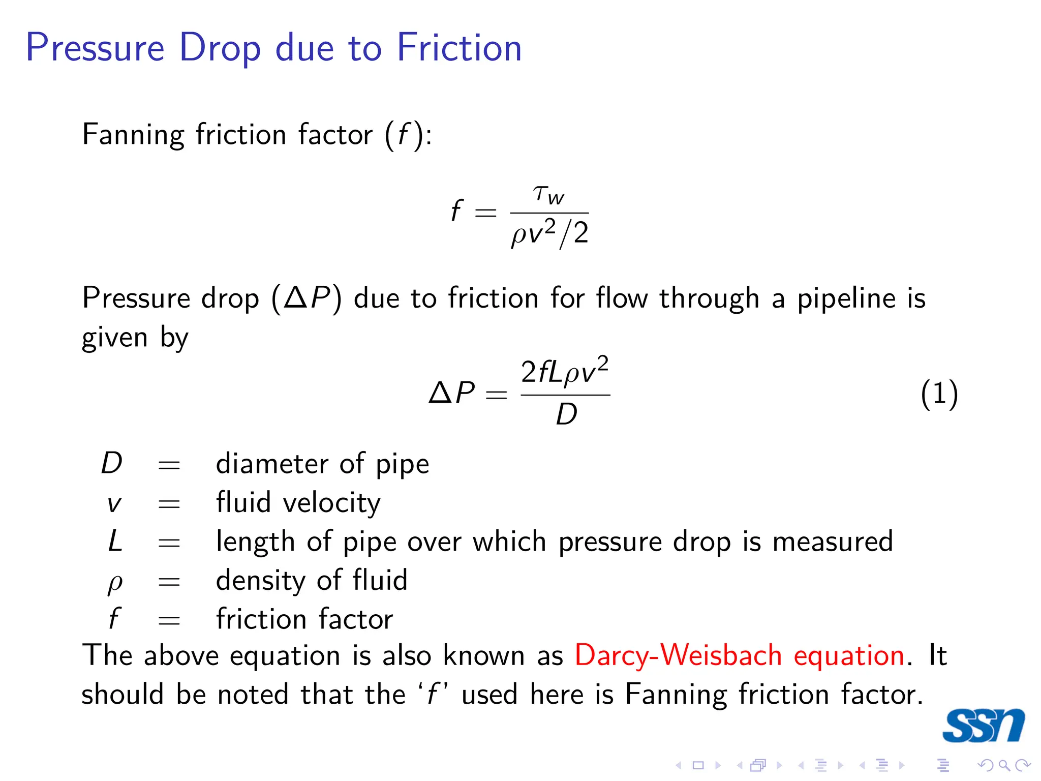
3) Pressure differences in fluids are used to measure pressure. Devices like manometers use columns of liquid to measure differences in pressure. Bernoulli's equation relates pressure and velocity in fluid flow.