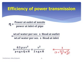
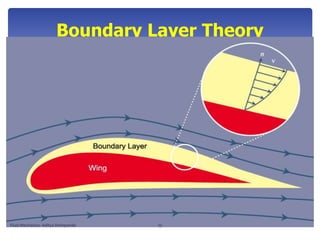
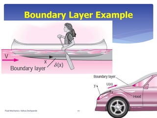
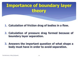
The document covers fluid mechanics concepts including friction factors, pipe losses, and the principles of lift and drag. It details various equations and methodologies such as Darcy-Weisbach and Chezy's formulas for calculating energy losses in fluid flow. Additionally, it includes practical examples and problems related to the application of these principles in real-world scenarios.

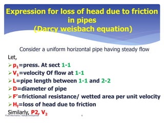
![(Darcy weisbach equation)
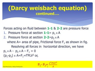
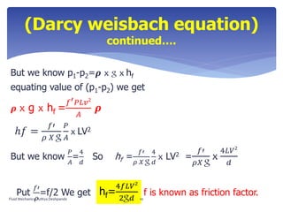
continued….
But, hf is head loss due to friction and intensity of pressure
will be reduced in direction of flow by frictional resistance.
Frictional resistance=
frictional resistance per unit wetted area per unit velocity x
wetted area x V2
So,
F1=f’ x πd L x V2 [ wetted area= πdL , V=V1=V2 ]
F1= f’ x PL V2 [ P=perimeter=P ]
Fluid Mechanics- Aditya Deshpande 8](https://image.slidesharecdn.com/fluidmechanics-flows-190322065625/85/Fluid-Mechanics-Flows-8-320.jpg)