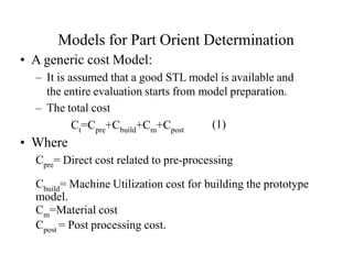
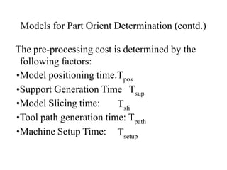
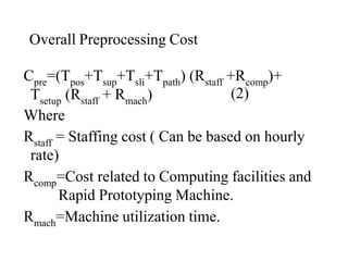
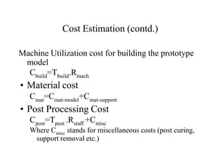
Part Orientation and Support
Generation
Factors Affecting Part Orientation
• The main envelope of the part in 3D is one of the
important factors. For SLA, switching between
individual layers takes a significant part of the
overall building time, hence must be properly
optimized.
• For FDM, there is no difference between the total
building time for adding the modeling materials.
But it is still better, where possible, to orient the
the part such that the part would firmly stand on
the platform during the building process.
Factors Affecting Part Orientation
(contd)
• For processes that need support structures,
part orientation should also be optimized
such that it would require minimal support.
–There are two key parameters:
•While ensuring that the part is firmly supported during the
entire prototyping process, the overall support contact area
should be minimized. This helps in minimizing the
influence of the support on the surface quality of the
prototype. Post processing efforts are reduced. The total
support volume should also be minimized to save time and
material.
Factors Affecting Part Orientation
(contd)
– The external surfaces produces should be as
smooth as possible. This can be achieved by
reducing the number of areas of inclined faces.
• Other factors such as trapped volume should
be avoided in case of SLA. Possible curling
should also be considered.
Models for Part Orient Determination
• A generic cost Model:
– It is assumed that a good STL model is available and
the entire evaluation starts from model preparation.
– The total cost
Ct=Cpre+Cbuild+Cm+Cpost
(1)
• Where
Cpre= Direct cost related to pre-processing
Cbuild= Machine Utilization cost for building the prototype
model.
Cm=Material cost
Cpost = Post processing cost.
Models for Part Orient Determination (contd.)
The pre-processing cost is determined by the
following factors:
•Model positioning time.Tpos
•Support Generation Time Tsup
•Model Slicing time: Tsli
•Tool path generation time: Tpath
•Machine Setup Time: Tsetup
Overall Preprocessing Cost
Cpre=(Tpos+Tsup+Tsli+Tpath) (Rstaff +Rcomp)+
(2)
Tsetup (Rstaff + Rmach)
Where
Rstaff = Staffing cost ( Can be based on hourly
rate)
Rcomp=Cost related to Computing facilities and
Rapid Prototyping Machine.
Rmach=Machine utilization time.
Overall Preprocessing Cost (contd.)
• Machine utilization cost can be estimated
based on initial machine cost after
considering machine depreciation.
Cost Estimation (contd.)
Machine Utilization cost for building the prototype
model
Cbuild=Tbuild.Rmach
• Material cost
Cmat=Cmat-model+Cmat-support
• Post Processing Cost
Cpost=Tpost .Rstaff +Cmisc
Where Cmisc stands for miscellaneous costs (post curing,
support removal etc.)
Cost Estimation (contd.)
• Build time estimation varies from process to
process and it dictates the overall cost.
• In case of SLA it depends on the laser spot
dimension, the laser power that determines
the scanning speed and the hatching pattern.
The switching time between two
consecutive layers also contributes
significantly in the overall build time.
Cost Estimation (contd.)
• In case of SLS process, the build time mainly
depends on the laser drawing speed.
• In case of FDM, the overall building time for a
given modeling material is usually not sensitive to
part orientation, but part orientation will largely
affect the consumption of support material. Part
orientation will thus directly influence the overall
building time and post processing time.
Cost Estimation (contd.)
• In many situations, one can produce multiple parts
in a single setup. This is substantially useful for
processes such as SLA and SLS that involve
substantial times while switching between layers.
• In addition to part orientation, another technical
issue concerns how one should pack the part in 3D
in order to achieve maximum utilization of the
machine capacity.
Part Orientation for surface
quality improvement
Part orientation and Surface quality
• While minimizing overall cost, the surface quality of final
prototype model must be kept in mind.
• For fixed building orientation, the minimization of
building time and hence overall cost is an optimization
issue related to surface quality improvement.
–If a small layer thickness is used, one would obtain
a fine part surface, but the overall build time will be
longer and hence the surface quality is improved at
a cost.
–It is however, possible by adjusting the part
orientation to obtain an optimal solution with
acceptable surface quality at a bearable cost.
θ
d
Ve = Volumetric error
d = Layer thickness
li = Perimeter at Layer I,
n = Total number of Layers
n n 2
Ve = Σ i=1 Ai li = Σ i=1 (0.5 d tan θ li)
Stair-casing Error Evaluation
Part Orientation with minimum Support
• Part orientation will affect the volume of the
material required for model support and hence
build time (for some RP processes).
• Overhanging part areas having direct contact with
support will have a poor surface finish and require
more post- processing.
• The volume of support includes all areas under
down-facing and overhanging facets (both in inner
as well as outer part surface).
Support Structures
Supports
and Base
Platform
Part
Part Orientation with minimum Support
• For a given facet of STL model, if the facet
normal is pointing downward on the outer part
surface or the inner surface surrounding an
internal void, and the inclination angle between
the facet and the horizontal slicing plane is smaller
than 250, the facet is considered a downward
facing and overhanging facet while calculating
support volume.
• If the angle is > 250, the structure is considered
self supporting.
Part Orientation with minimum Support
(contd.)
• The support volume can be computed as follows:
V = Σn
sup i=1
V = Σn A h
i i=1 i i
Where
• n = total number of downward facing and
overhanging facets.
• Ai is the projected area of facet i on to the
horizontal plane.
• hi =The average support height.
Part Orientation (multiple objective optimization)
• In general, a part should be oriented to meet the following
criteria:
– Maximum number of perpendicular surfaces.
– Maximum number of up-facing horizontal surfaces.
– Maximum numbers of holes with their axis in the slicing direction.
– Maximum number of curved cross-sections drawn in the horizontal
plane.
– Maximize the area of the base surface.
– Minimize the number of sloped surface.
– Minimize the total area of overhanging surfaces.
– Minimize the number of trapped volumes.
– Minimize total number of slices
– Minimize the height of the required support structures.
Functions of Part Support
• To separate parts from platform.
– Easy and safe to remove part.
– Marks on the platform will not be printed on the part.
• To provide support to overhang structures.
– Prevent structure from collapsing and strengthening
overhang regions.
• To provide collision avoidance buffer.
• Process improvement.
– To improve liquid flow in and around the part for SLA
process (initial build stages & while switching between
individual layers).

Part Orientation & Support Structures

  • 1.
    Part Orientation andSupport Generation
  • 2.
    Factors Affecting PartOrientation • The main envelope of the part in 3D is one of the important factors. For SLA, switching between individual layers takes a significant part of the overall building time, hence must be properly optimized. • For FDM, there is no difference between the total building time for adding the modeling materials. But it is still better, where possible, to orient the the part such that the part would firmly stand on the platform during the building process.
  • 3.
    Factors Affecting PartOrientation (contd) • For processes that need support structures, part orientation should also be optimized such that it would require minimal support. –There are two key parameters: •While ensuring that the part is firmly supported during the entire prototyping process, the overall support contact area should be minimized. This helps in minimizing the influence of the support on the surface quality of the prototype. Post processing efforts are reduced. The total support volume should also be minimized to save time and material.
  • 4.
    Factors Affecting PartOrientation (contd) – The external surfaces produces should be as smooth as possible. This can be achieved by reducing the number of areas of inclined faces. • Other factors such as trapped volume should be avoided in case of SLA. Possible curling should also be considered.
  • 5.
    Models for PartOrient Determination • A generic cost Model: – It is assumed that a good STL model is available and the entire evaluation starts from model preparation. – The total cost Ct=Cpre+Cbuild+Cm+Cpost (1) • Where Cpre= Direct cost related to pre-processing Cbuild= Machine Utilization cost for building the prototype model. Cm=Material cost Cpost = Post processing cost.
  • 6.
    Models for PartOrient Determination (contd.) The pre-processing cost is determined by the following factors: •Model positioning time.Tpos •Support Generation Time Tsup •Model Slicing time: Tsli •Tool path generation time: Tpath •Machine Setup Time: Tsetup
  • 7.
    Overall Preprocessing Cost Cpre=(Tpos+Tsup+Tsli+Tpath)(Rstaff +Rcomp)+ (2) Tsetup (Rstaff + Rmach) Where Rstaff = Staffing cost ( Can be based on hourly rate) Rcomp=Cost related to Computing facilities and Rapid Prototyping Machine. Rmach=Machine utilization time.
  • 8.
    Overall Preprocessing Cost(contd.) • Machine utilization cost can be estimated based on initial machine cost after considering machine depreciation.
  • 9.
    Cost Estimation (contd.) MachineUtilization cost for building the prototype model Cbuild=Tbuild.Rmach • Material cost Cmat=Cmat-model+Cmat-support • Post Processing Cost Cpost=Tpost .Rstaff +Cmisc Where Cmisc stands for miscellaneous costs (post curing, support removal etc.)
  • 10.
    Cost Estimation (contd.) •Build time estimation varies from process to process and it dictates the overall cost. • In case of SLA it depends on the laser spot dimension, the laser power that determines the scanning speed and the hatching pattern. The switching time between two consecutive layers also contributes significantly in the overall build time.
  • 11.
    Cost Estimation (contd.) •In case of SLS process, the build time mainly depends on the laser drawing speed. • In case of FDM, the overall building time for a given modeling material is usually not sensitive to part orientation, but part orientation will largely affect the consumption of support material. Part orientation will thus directly influence the overall building time and post processing time.
  • 12.
    Cost Estimation (contd.) •In many situations, one can produce multiple parts in a single setup. This is substantially useful for processes such as SLA and SLS that involve substantial times while switching between layers. • In addition to part orientation, another technical issue concerns how one should pack the part in 3D in order to achieve maximum utilization of the machine capacity.
  • 13.
    Part Orientation forsurface quality improvement
  • 14.
    Part orientation andSurface quality • While minimizing overall cost, the surface quality of final prototype model must be kept in mind. • For fixed building orientation, the minimization of building time and hence overall cost is an optimization issue related to surface quality improvement. –If a small layer thickness is used, one would obtain a fine part surface, but the overall build time will be longer and hence the surface quality is improved at a cost. –It is however, possible by adjusting the part orientation to obtain an optimal solution with acceptable surface quality at a bearable cost.
  • 15.
    θ d Ve = Volumetricerror d = Layer thickness li = Perimeter at Layer I, n = Total number of Layers n n 2 Ve = Σ i=1 Ai li = Σ i=1 (0.5 d tan θ li) Stair-casing Error Evaluation
  • 17.
    Part Orientation withminimum Support • Part orientation will affect the volume of the material required for model support and hence build time (for some RP processes). • Overhanging part areas having direct contact with support will have a poor surface finish and require more post- processing. • The volume of support includes all areas under down-facing and overhanging facets (both in inner as well as outer part surface).
  • 18.
  • 19.
    Part Orientation withminimum Support • For a given facet of STL model, if the facet normal is pointing downward on the outer part surface or the inner surface surrounding an internal void, and the inclination angle between the facet and the horizontal slicing plane is smaller than 250, the facet is considered a downward facing and overhanging facet while calculating support volume. • If the angle is > 250, the structure is considered self supporting.
  • 20.
    Part Orientation withminimum Support (contd.) • The support volume can be computed as follows: V = Σn sup i=1 V = Σn A h i i=1 i i Where • n = total number of downward facing and overhanging facets. • Ai is the projected area of facet i on to the horizontal plane. • hi =The average support height.
  • 21.
    Part Orientation (multipleobjective optimization) • In general, a part should be oriented to meet the following criteria: – Maximum number of perpendicular surfaces. – Maximum number of up-facing horizontal surfaces. – Maximum numbers of holes with their axis in the slicing direction. – Maximum number of curved cross-sections drawn in the horizontal plane. – Maximize the area of the base surface. – Minimize the number of sloped surface. – Minimize the total area of overhanging surfaces. – Minimize the number of trapped volumes. – Minimize total number of slices – Minimize the height of the required support structures.
  • 22.
    Functions of PartSupport • To separate parts from platform. – Easy and safe to remove part. – Marks on the platform will not be printed on the part. • To provide support to overhang structures. – Prevent structure from collapsing and strengthening overhang regions. • To provide collision avoidance buffer. • Process improvement. – To improve liquid flow in and around the part for SLA process (initial build stages & while switching between individual layers).