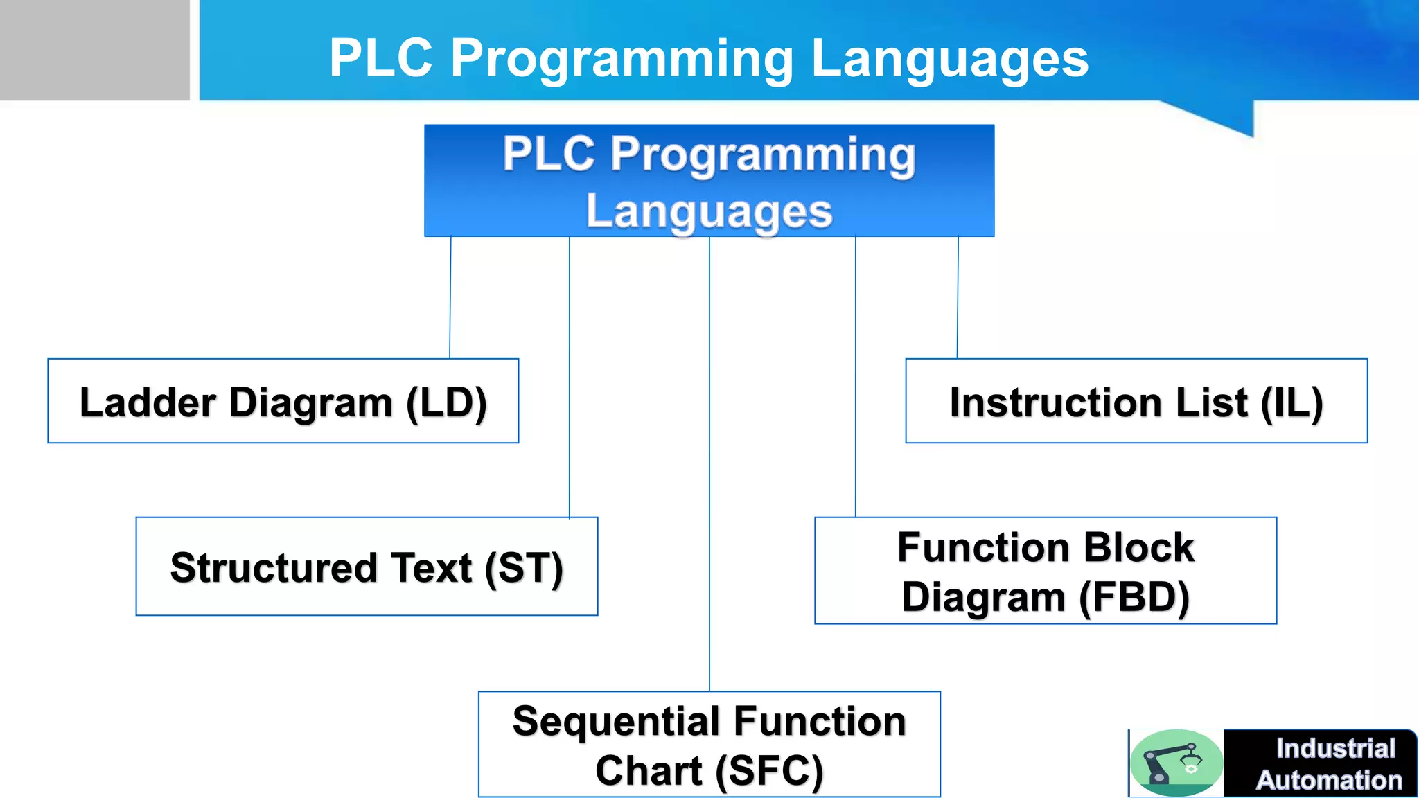
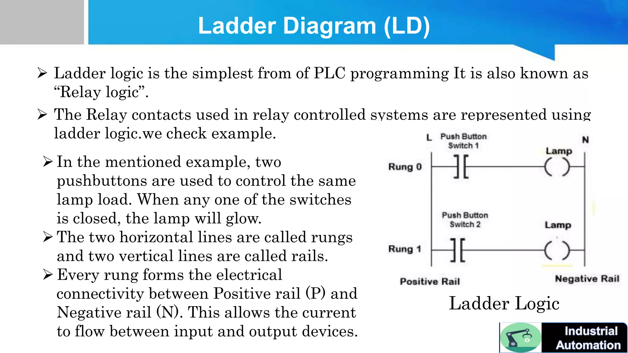
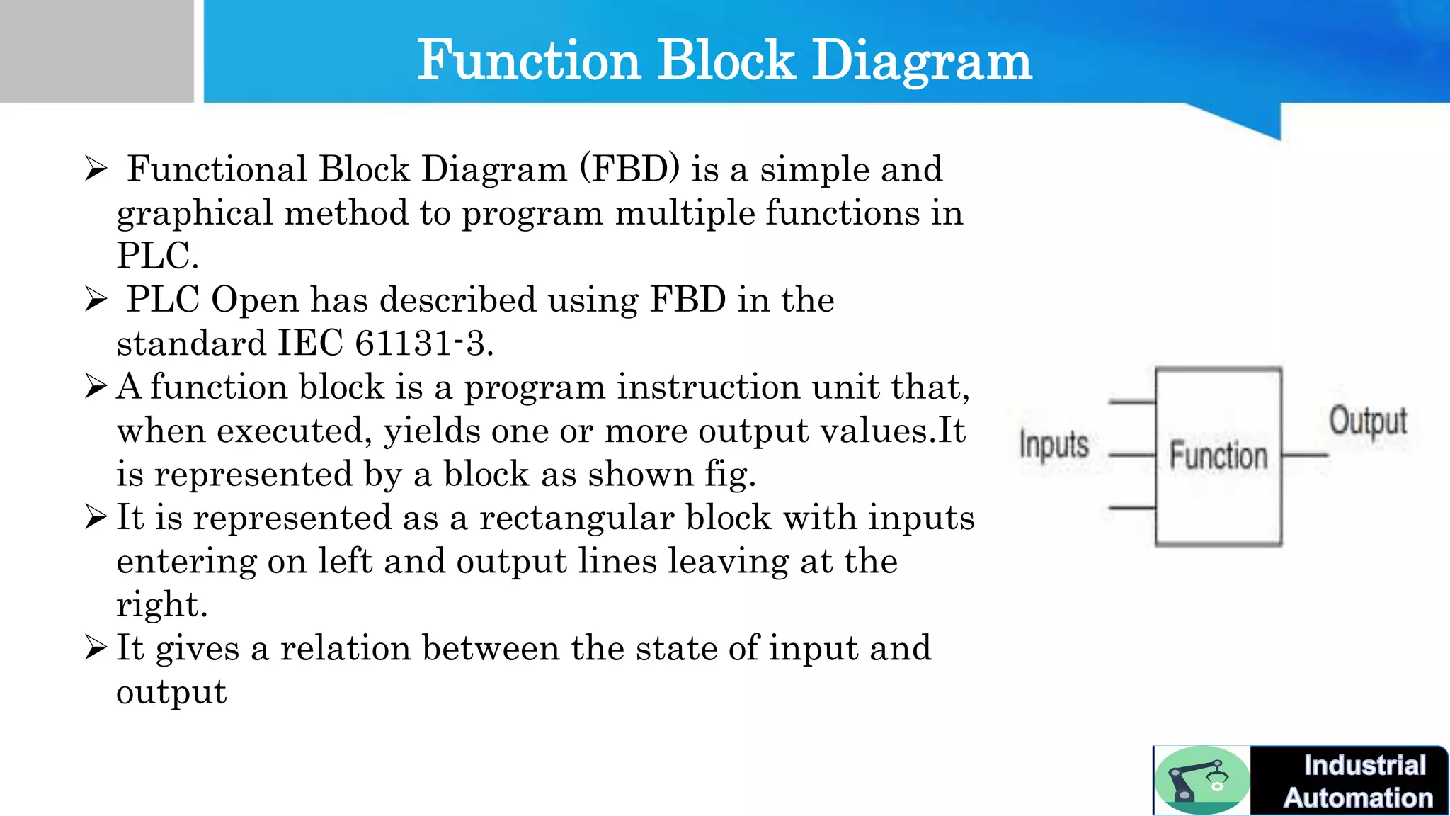
PLC Programming
Languages
PLC Programming Languages
Ladder Diagram (LD)
Structured Text (ST)
Sequential Function
Chart (SFC)
Function Block
Diagram (FBD)
Instruction List (IL)
Ladder Diagram (LD)
 Ladder logic is the simplest from of PLC programming It is also known as
“Relay logic”.
 The Relay contacts used in relay controlled systems are represented using
ladder logic.we check example.
Ladder Logic
In the mentioned example, two
pushbuttons are used to control the same
lamp load. When any one of the switches
is closed, the lamp will glow.
The two horizontal lines are called rungs
and two vertical lines are called rails.
Every rung forms the electrical
connectivity between Positive rail (P) and
Negative rail (N). This allows the current
to flow between input and output devices.
Function Block Diagram
 Functional Block Diagram (FBD) is a simple and
graphical method to program multiple functions in
PLC.
 PLC Open has described using FBD in the
standard IEC 61131-3.
A function block is a program instruction unit that,
when executed, yields one or more output values.It
is represented by a block as shown fig.
It is represented as a rectangular block with inputs
entering on left and output lines leaving at the
right.
It gives a relation between the state of input and
output
Next Video Topic
 PLC Scan Time....
Don't Forget Like And Share.

Part 6 PLC languges.

  • 1.
  • 2.
    PLC Programming Languages LadderDiagram (LD) Structured Text (ST) Sequential Function Chart (SFC) Function Block Diagram (FBD) Instruction List (IL)
  • 3.
    Ladder Diagram (LD) Ladder logic is the simplest from of PLC programming It is also known as “Relay logic”.  The Relay contacts used in relay controlled systems are represented using ladder logic.we check example. Ladder Logic In the mentioned example, two pushbuttons are used to control the same lamp load. When any one of the switches is closed, the lamp will glow. The two horizontal lines are called rungs and two vertical lines are called rails. Every rung forms the electrical connectivity between Positive rail (P) and Negative rail (N). This allows the current to flow between input and output devices.
  • 4.
    Function Block Diagram Functional Block Diagram (FBD) is a simple and graphical method to program multiple functions in PLC.  PLC Open has described using FBD in the standard IEC 61131-3. A function block is a program instruction unit that, when executed, yields one or more output values.It is represented by a block as shown fig. It is represented as a rectangular block with inputs entering on left and output lines leaving at the right. It gives a relation between the state of input and output
  • 5.
    Next Video Topic PLC Scan Time....
  • 6.