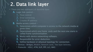
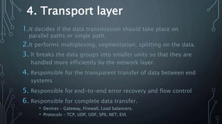
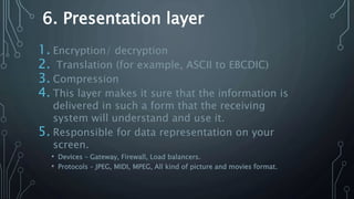
Submitted to
Dr. Govind Singh
Faculty of engineering and technology
M.G.C.G.V. Chitrakoot, Satna
(M.P.) – 485334
Submitted by
Name - Shubham Mishra
Roll N. - 5
Branch- I.T.
Semester- 6th
Date- 23/03/2018
Presentation on
Topic- OSI Model
Introduction
1. The Open Systems Interconnection (OSI) model is created as a framework
and reference model to explain how networking technologies work
together.
2. It is primarily used today as a Reference model/teaching tool.
3. This model is developed by the International Organization Of
Standardization (ISO) in 1978.
4. This model provide clear distinction between service, interface and
protocols.
5. Big picture of communication over network is understood able through
this model.
6. The OSI model breaks up the process of network communications into 7
layers that consist of various protocols and different technologies that
work in tandem from one layer to the next in order to process, and
transfer data among computer networks that traverse the internet.
7. We can understand how information should be handled when being
transported over a network.
Features of OSI model
1. Big picture of communication over network is
understoodable through this model.
2. We can see how hardware and software works
together.
3. We can understand new network technologies as
they are developed.
4. The OSI model also provides a guide for
troubleshooting network problems by tracking them
down to a specific layer.
5. Protocols of OSI model are very well hidden and
Layers of OSI model
1.Physical layer
2.Data link layer
3.Network layer
4.Transport layer
5.Session layer
6.Presentation
layer
7.Application layer
1. Physical layer
A.It provide interface for communication of data.
B.The numbers of bits transmitted per second are also
defined by the physical layer.
C.The sender and the receiver should be synchronized
at the same bit rate and this job is also done by the
physical layer.
D.It converts Digital/Analog bits into
Electrical/Optical signal.
E. Voltage and data rates are nodded for transmission
is defined in physical layer.
F. Data encoding is also defined in this layer.
2. Data link layer
• There are two sublayers of datalink layer
A. Logic link control –
1. Flow control
2. Error correcting
3. Creates IP address
B. Media access control –
1. Determines which computer is access to the network media at
given time.
2. Determined which one frame ends and the next one starts is
called frame synchronisation.
3. Works with device networking software.
4. Responsible for error deduction.
5. Define hardware or physical topology for connection.
• Devices – Bridges, Modem, Network cards, Two layer Switches.
• Protocols – HDLC, ATM, SLIP, PPP, LLC, MAC.
3. Network layer
1. It routes the signals through different channels from one end
to another.
2. It acts as network controller, it manages the subnet traffic.
3. It decided by which rout data should to send.
4. It devides the outgoing message into packets and assemble
incoming packets into messages for higher level.
5. Implements routing of frames (packets) through a network.
• Devices – Router, Three layer switches.
• Protocols - IP, IPX, RIPICMP, ARP, IGMP, ICMP, ETC.
4. Transport layer
1.It decides if the data transmission should take place on
parallel paths or single path.
2.It performs multiplexing, segmentation, splitting on the data.
3. It breaks the data groups into smaller units so that they are
handled more efficiently by the network layer.
4. Responsible for the transparent transfer of data between end
systems
5. Responsible for end-to-end error recovery and flow control
6. Responsible for complete data transfer.
• Devices – Gateway, Firewall, Load balancers.
• Protocols – TCP, UDP, UDF, SPX, NET, EVI.
5. Session layer
1. Responsible for establishment, management and termination
of connections between applications.
2. It deals with session and connection coordination.
3. It controls logging on and off, user identification, billing and
session management.
4. The session layer determines which device will communicate
first and the amount of data that will be sent.
• Devices – Gateway, Firewall, Load balancers.
• Protocols - NFS, NetBios names, RPC, SQL, PPTP,
6. Presentation layer
1. Encryption/ decryption
2. Translation (for example, ASCII to EBCDIC)
3. Compression
4. This layer makes it sure that the information is
delivered in such a form that the receiving
system will understand and use it.
5. Responsible for data representation on your
screen.
• Devices – Gateway, Firewall, Load balancers.
• Protocols – JPEG, MIDI, MPEG, All kind of picture and movies format.
7. Application layer
1. Application layer supports application, apps, and end-user
processes.
2. Quality of service
3. This layer is responsible for application services for file
transfers, e-mail, and other network software services.
4. The functions such as LOGIN or password checking are also
performed by the application layer.
5. FTAM-File transfer access and management
• Devices – Gateway, Firewall, all end devices like PS’s Mobile phones etc.
• Protocols - Telnet, FTP, HTTP, SNMP, WWW, SMB, NFS, SMTP.
Merits
• Protocols of OSI model are very well hidden.
• Protocols can be replaced by new protocols as
technology changes.
• Support connection oriented services as well as
connectionless service.
Demerits
• The model was invented before the invention of
protocols.
• Fitting of protocols is tedious task.
• It is just used as a reference model.
Thankyou

Osi model

  • 1.
    Submitted to Dr. GovindSingh Faculty of engineering and technology M.G.C.G.V. Chitrakoot, Satna (M.P.) – 485334 Submitted by Name - Shubham Mishra Roll N. - 5 Branch- I.T. Semester- 6th Date- 23/03/2018 Presentation on Topic- OSI Model
  • 2.
    Introduction 1. The OpenSystems Interconnection (OSI) model is created as a framework and reference model to explain how networking technologies work together. 2. It is primarily used today as a Reference model/teaching tool. 3. This model is developed by the International Organization Of Standardization (ISO) in 1978. 4. This model provide clear distinction between service, interface and protocols. 5. Big picture of communication over network is understood able through this model. 6. The OSI model breaks up the process of network communications into 7 layers that consist of various protocols and different technologies that work in tandem from one layer to the next in order to process, and transfer data among computer networks that traverse the internet. 7. We can understand how information should be handled when being transported over a network.
  • 3.
    Features of OSImodel 1. Big picture of communication over network is understoodable through this model. 2. We can see how hardware and software works together. 3. We can understand new network technologies as they are developed. 4. The OSI model also provides a guide for troubleshooting network problems by tracking them down to a specific layer. 5. Protocols of OSI model are very well hidden and
  • 4.
    Layers of OSImodel 1.Physical layer 2.Data link layer 3.Network layer 4.Transport layer 5.Session layer 6.Presentation layer 7.Application layer
  • 5.
    1. Physical layer A.Itprovide interface for communication of data. B.The numbers of bits transmitted per second are also defined by the physical layer. C.The sender and the receiver should be synchronized at the same bit rate and this job is also done by the physical layer. D.It converts Digital/Analog bits into Electrical/Optical signal. E. Voltage and data rates are nodded for transmission is defined in physical layer. F. Data encoding is also defined in this layer.
  • 6.
    2. Data linklayer • There are two sublayers of datalink layer A. Logic link control – 1. Flow control 2. Error correcting 3. Creates IP address B. Media access control – 1. Determines which computer is access to the network media at given time. 2. Determined which one frame ends and the next one starts is called frame synchronisation. 3. Works with device networking software. 4. Responsible for error deduction. 5. Define hardware or physical topology for connection. • Devices – Bridges, Modem, Network cards, Two layer Switches. • Protocols – HDLC, ATM, SLIP, PPP, LLC, MAC.
  • 7.
    3. Network layer 1.It routes the signals through different channels from one end to another. 2. It acts as network controller, it manages the subnet traffic. 3. It decided by which rout data should to send. 4. It devides the outgoing message into packets and assemble incoming packets into messages for higher level. 5. Implements routing of frames (packets) through a network. • Devices – Router, Three layer switches. • Protocols - IP, IPX, RIPICMP, ARP, IGMP, ICMP, ETC.
  • 8.
    4. Transport layer 1.Itdecides if the data transmission should take place on parallel paths or single path. 2.It performs multiplexing, segmentation, splitting on the data. 3. It breaks the data groups into smaller units so that they are handled more efficiently by the network layer. 4. Responsible for the transparent transfer of data between end systems 5. Responsible for end-to-end error recovery and flow control 6. Responsible for complete data transfer. • Devices – Gateway, Firewall, Load balancers. • Protocols – TCP, UDP, UDF, SPX, NET, EVI.
  • 9.
    5. Session layer 1.Responsible for establishment, management and termination of connections between applications. 2. It deals with session and connection coordination. 3. It controls logging on and off, user identification, billing and session management. 4. The session layer determines which device will communicate first and the amount of data that will be sent. • Devices – Gateway, Firewall, Load balancers. • Protocols - NFS, NetBios names, RPC, SQL, PPTP,
  • 10.
    6. Presentation layer 1.Encryption/ decryption 2. Translation (for example, ASCII to EBCDIC) 3. Compression 4. This layer makes it sure that the information is delivered in such a form that the receiving system will understand and use it. 5. Responsible for data representation on your screen. • Devices – Gateway, Firewall, Load balancers. • Protocols – JPEG, MIDI, MPEG, All kind of picture and movies format.
  • 11.
    7. Application layer 1.Application layer supports application, apps, and end-user processes. 2. Quality of service 3. This layer is responsible for application services for file transfers, e-mail, and other network software services. 4. The functions such as LOGIN or password checking are also performed by the application layer. 5. FTAM-File transfer access and management • Devices – Gateway, Firewall, all end devices like PS’s Mobile phones etc. • Protocols - Telnet, FTP, HTTP, SNMP, WWW, SMB, NFS, SMTP.
  • 12.
    Merits • Protocols ofOSI model are very well hidden. • Protocols can be replaced by new protocols as technology changes. • Support connection oriented services as well as connectionless service. Demerits • The model was invented before the invention of protocols. • Fitting of protocols is tedious task. • It is just used as a reference model.
  • 13.