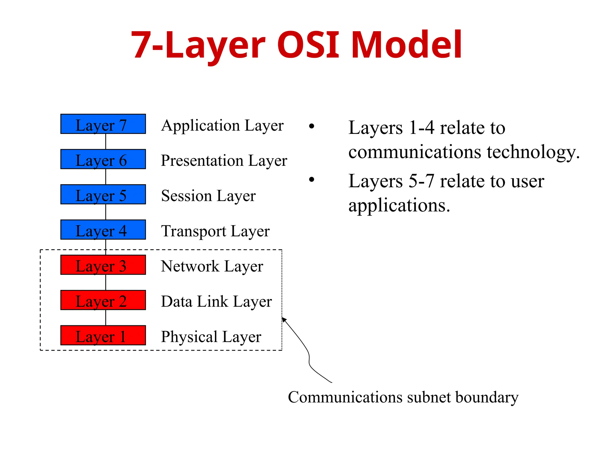
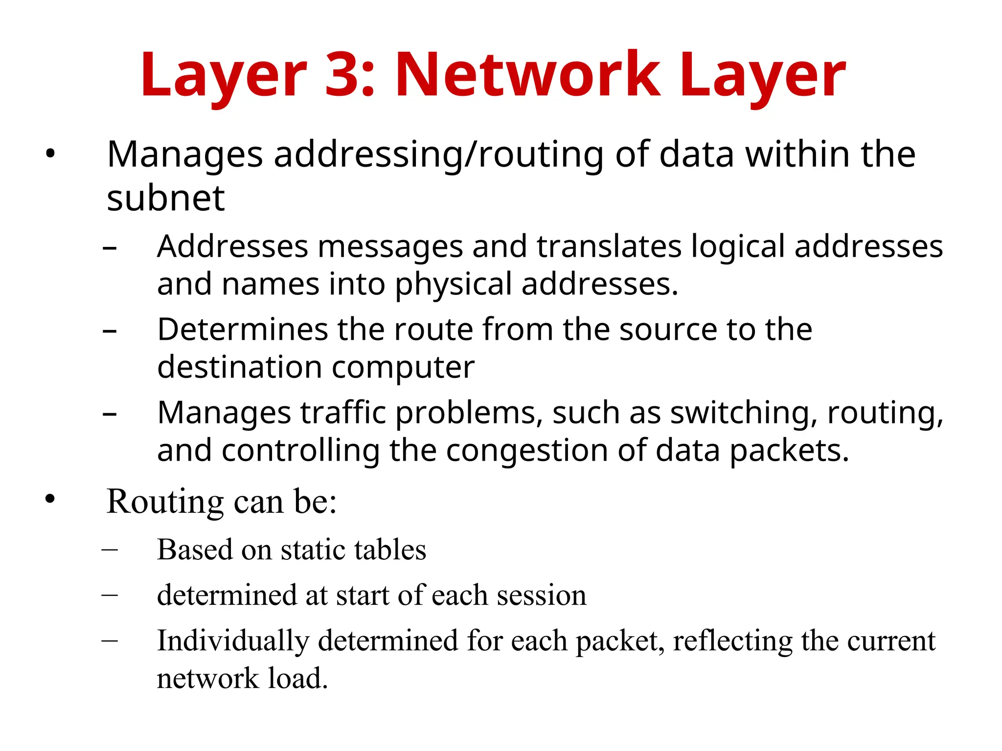
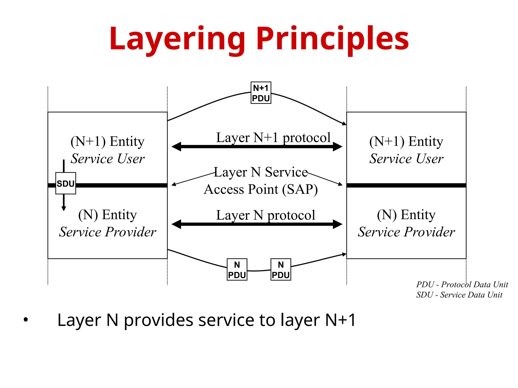
OSI Model
• The OSI reference model
• Services in the OSI model
Topics
• OSI Reference Model - internationally
standardised network architecture.
• OSI = Open Systems Interconnection: deals
with open systems, i.e. systems open for
communications with other systems.
• Specified in ISO 7498.
• Model has 7 layers.
OSI Reference Model
• Layers 1-4 relate to
communications technology.
• Layers 5-7 relate to user
applications.
7-Layer OSI Model
Layer 7
Layer 6
Layer 5
Layer 4
Layer 3
Layer 2
Layer 1
Application Layer
Presentation Layer
Session Layer
Transport Layer
Network Layer
Data Link Layer
Physical Layer
Communications subnet boundary
• Level at which applications access
network services.
– Represents services that directly support
software applications for file transfers,
database access, and electronic mail etc.
Layer 7: Application Layer
• Related to representation of transmitted
data
– Translates different data representations
from the Application layer into uniform
standard format
• Providing services for secure efficient
data transmission
– e.g. data encryption, and data compression.
Layer 6: Presentation
Layer
• Allows two applications on different
computers to establish, use, and end a
session.
– e.g. file transfer, remote login
• Establishes dialog control
– Regulates which side transmits, plus when and
how long it transmits.
• Performs token management and synchronization.
Layer 5: Session Layer
• Manages transmission packets
– Repackages long messages when
necessary into small packets for
transmission
– Reassembles packets in correct order to get
the original message.
• Handles error recognition and recovery.
– Transport layer at receiving acknowledges
packet delivery.
– Resends missing packets
Layer 4: Transport Layer
• Manages addressing/routing of data within the
subnet
– Addresses messages and translates logical addresses
and names into physical addresses.
– Determines the route from the source to the
destination computer
– Manages traffic problems, such as switching, routing,
and controlling the congestion of data packets.
• Routing can be:
– Based on static tables
– determined at start of each session
– Individually determined for each packet, reflecting the current
network load.
Layer 3: Network Layer
 Packages raw bits from the Physical
layer into frames (logical, structured
packets for data).
 Provides reliable transmission of frames
 It waits for an acknowledgment from the
receiving computer.
 Retransmits frames for which
acknowledgement not received
Layer 2: Data Link Layer
• Transmits bits from one computer to another
• Regulates the transmission of a stream of bits
over a physical medium.
• Defines how the cable is attached to the
network adapter and what transmission
technique is used to send data over the cable.
Deals with issues like
– The definition of 0 and 1, e.g. how many volts represents a
1, and how long a bit lasts?
– Whether the channel is simplex or duplex?
– How many pins a connector has, and what the function of
each pin is?
Layer 1: Physical Layer
• Explicit
Presentation and
session layers
missing in Internet
Protocols
• Data Link and
Network Layers
redesigned
Internet Protocols vs OSI
Application
Presentation
Session
Transport
Network
Data Link
Physical
Application
TCP
IP
Network Interface
Hardware
• In OSI model, each layer provide services to
layer above, and ‘consumes’ services provided
by layer below.
• Active elements in a layer called entities.
• Entities in same layer in different machines
called peer entities.
Services in the OSI Model
• Layer N provides service to layer N+1
Layering Principles
(N+1) Entity
Service User
(N) Entity
Service Provider
(N+1) Entity
Service User
(N) Entity
Service Provider
Layer N Service
Access Point (SAP)
Layer N protocol
N+1
PDU
Layer N+1 protocol
SDU
PDU - Protocol Data Unit
SDU - Service Data Unit
N
PDU
N
PDU
• Layers can offer connection-oriented or
connectionless services.
• Connection-oriented like telephone system.
• Connectionless like postal system.
• Each service has an associated Quality-of-
service (e.g. reliable or unreliable).
Connections
• Reliable services never lose/corrupt data.
• Reliable service costs more.
• Typical application for reliable service is file
transfer.
• Typical application not needing reliable service
is voice traffic.
• Not all applications need connections.
Reliability
• Service = set of primitives provided by one
layer to layer above.
• Service defines what layer can do (but not how
it does it).
• Protocol = set of rules governing data
communication between peer entities, i.e.
format and meaning of frames/packets.
• Service/protocol decoupling very important.
Topics

46-cnvrhhbrfbi jjjhfurhfhuffuirhhfhfiu.ppt

  • 1.
  • 2.
    • The OSIreference model • Services in the OSI model Topics
  • 3.
    • OSI ReferenceModel - internationally standardised network architecture. • OSI = Open Systems Interconnection: deals with open systems, i.e. systems open for communications with other systems. • Specified in ISO 7498. • Model has 7 layers. OSI Reference Model
  • 4.
    • Layers 1-4relate to communications technology. • Layers 5-7 relate to user applications. 7-Layer OSI Model Layer 7 Layer 6 Layer 5 Layer 4 Layer 3 Layer 2 Layer 1 Application Layer Presentation Layer Session Layer Transport Layer Network Layer Data Link Layer Physical Layer Communications subnet boundary
  • 5.
    • Level atwhich applications access network services. – Represents services that directly support software applications for file transfers, database access, and electronic mail etc. Layer 7: Application Layer
  • 6.
    • Related torepresentation of transmitted data – Translates different data representations from the Application layer into uniform standard format • Providing services for secure efficient data transmission – e.g. data encryption, and data compression. Layer 6: Presentation Layer
  • 7.
    • Allows twoapplications on different computers to establish, use, and end a session. – e.g. file transfer, remote login • Establishes dialog control – Regulates which side transmits, plus when and how long it transmits. • Performs token management and synchronization. Layer 5: Session Layer
  • 8.
    • Manages transmissionpackets – Repackages long messages when necessary into small packets for transmission – Reassembles packets in correct order to get the original message. • Handles error recognition and recovery. – Transport layer at receiving acknowledges packet delivery. – Resends missing packets Layer 4: Transport Layer
  • 9.
    • Manages addressing/routingof data within the subnet – Addresses messages and translates logical addresses and names into physical addresses. – Determines the route from the source to the destination computer – Manages traffic problems, such as switching, routing, and controlling the congestion of data packets. • Routing can be: – Based on static tables – determined at start of each session – Individually determined for each packet, reflecting the current network load. Layer 3: Network Layer
  • 10.
     Packages rawbits from the Physical layer into frames (logical, structured packets for data).  Provides reliable transmission of frames  It waits for an acknowledgment from the receiving computer.  Retransmits frames for which acknowledgement not received Layer 2: Data Link Layer
  • 11.
    • Transmits bitsfrom one computer to another • Regulates the transmission of a stream of bits over a physical medium. • Defines how the cable is attached to the network adapter and what transmission technique is used to send data over the cable. Deals with issues like – The definition of 0 and 1, e.g. how many volts represents a 1, and how long a bit lasts? – Whether the channel is simplex or duplex? – How many pins a connector has, and what the function of each pin is? Layer 1: Physical Layer
  • 12.
    • Explicit Presentation and sessionlayers missing in Internet Protocols • Data Link and Network Layers redesigned Internet Protocols vs OSI Application Presentation Session Transport Network Data Link Physical Application TCP IP Network Interface Hardware
  • 13.
    • In OSImodel, each layer provide services to layer above, and ‘consumes’ services provided by layer below. • Active elements in a layer called entities. • Entities in same layer in different machines called peer entities. Services in the OSI Model
  • 14.
    • Layer Nprovides service to layer N+1 Layering Principles (N+1) Entity Service User (N) Entity Service Provider (N+1) Entity Service User (N) Entity Service Provider Layer N Service Access Point (SAP) Layer N protocol N+1 PDU Layer N+1 protocol SDU PDU - Protocol Data Unit SDU - Service Data Unit N PDU N PDU
  • 15.
    • Layers canoffer connection-oriented or connectionless services. • Connection-oriented like telephone system. • Connectionless like postal system. • Each service has an associated Quality-of- service (e.g. reliable or unreliable). Connections
  • 16.
    • Reliable servicesnever lose/corrupt data. • Reliable service costs more. • Typical application for reliable service is file transfer. • Typical application not needing reliable service is voice traffic. • Not all applications need connections. Reliability
  • 17.
    • Service =set of primitives provided by one layer to layer above. • Service defines what layer can do (but not how it does it). • Protocol = set of rules governing data communication between peer entities, i.e. format and meaning of frames/packets. • Service/protocol decoupling very important. Topics

Editor's Notes

  • #3 The OSI model describes the flow of data in a network, from the lowest layer (the physical connections) up to the layer containing the user’s applications. Data going to and from the network is passed layer to layer. Each layer is able to communicate with the layer immediately above it and the layer immediately below it. This way, each layer is written as an efficient, streamlined software component. When a layer receives a packet of information, it checks the destination address, and if its own address is not there, it passes the packet to the next layer. When two computers communicate on a network, the software at each layer on one computer assumes it is communicating with the same layer on the other computer. For example, the Transport layer of one computer communicates with the Transport layer on the other computer. The Transport layer on the first computer has no regard for how the communication actually passes through the lower layers of the first computer, across the physical media, and then up through the lower layers of the second computer.
  • #4 The Application layer represents the level at which applications access network services. This layer represents the services that directly support applications such as software for file transfers, database access, and electronic mail.  The Presentation layer translates data from the Application layer into an intermediary format. This layer also manages security issues by providing services such as data encryption, and compresses data so that fewer bits need to be transferred on the network.  The Session layer allows two applications on different computers to establish, use, and end a session. This layer establishes dialog control between the two computers in a session, regulating which side transmits, plus when and how long it transmits.  The Transport layer handles error recognition and recovery. It also repackages long messages when necessary into small packets for transmission and, at the receiving end, rebuilds packets into the original message. The receiving Transport layer also sends receipt acknowledgments.  The Network layer addresses messages and translates logical addresses and names into physical addresses. It also determines the route from the source to the destination computer and manages traffic problems, such as switching, routing, and controlling the congestion of data packets.  The Data Link layer packages raw bits from the Physical layer into frames (logical, structured packets for data). This layer is responsible for transferring frames from one computer to another, without errors. After sending a frame, it waits for an acknowledgment from the receiving computer.  The Physical layer transmits bits from one computer to another and regulates the transmission of a stream of bits over a physical medium. This layer defines how the cable is attached to the network adapter and what transmission technique is used to send data over the cable This partition into ‘lower’ and ‘upper’ layers is a widely used way to distinguish between the communications-oriented layers and the applications- oriented layers. In fact layers 5 and 6 are often ignored in practical applications (the Internet protocol hierarchy has no equivalents to layers 5 and 6).
  • #5 The Application Layer is home to a wide variety of protocols to meet specific user needs. Network virtual terminal. Used by ‘networked screen editors’ and other networked applications needing to handle many different terminal types. Software exists to map the functions of the virtual terminal onto the real terminal, e.g. cursor movement. Examples include OSI VTP and Internet telnet. File transfer. Different file systems have different file naming conventions and internal record structures. Such a protocol must convert files to a ‘standard’ representation. Examples include OSI FTAM and Internet ftp. Electronic mail. Examples of electronic mail protocols are OSI X.400 and Internet mail. Directory service. Examples include OSI X.500.
  • #6 The Presentation Layer is concerned with the representation of data to be transmitted, e.g. providing a standard encoding for data. Different computers often use different representations for data structures such as characters (ASCII or EBCDIC), integers (one’s complement or two’s complement, and varying byte ordering conventions), and floating point values (IEEE or proprietary). The Presentation Layer provides a standard encoding technique (using ASN.1 - Abstract Syntax Notation 1). The Presentation Layer is also concerned with other representation issues such as data compression and encryption of data. In terms of the usual communications model, the Presentation Layer is responsible for source coding of data.
  • #7 The Session Layer allows the establishment of sessions between machines, e.g. to allow remote logins to a multi-user system, or to perform file transfer between machines. One of the Session services is dialogue control; if the communications are half-duplex then the session layer can manage which entity sends when. A related service is token management. In some protocols it is essential that both entities do not attempt the same operation simultaneously. Possession of a token permits the operation. The other main Session service is synchronization. As an example consider attempting a 2-hour file transfer between machines which crash on average once an hour. The synchronization service provides a means for checkpoints to be inserted into the data stream so that, after a crash, only data sent since the last checkpoint needs to be re-transmitted.
  • #8 The basic function of the Transport Layer is to take data from the Session Layer (Layer 5), split it up into smaller units (as necessary), and pass these units on to the Network Layer. It is then also responsible for ensuring that all the pieces are received correctly and reassembled in the correct order. Typically the Transport Layer will create a distinct Network Layer connection for each Transport connection requested by the Session Layer. However, depending on the data load and the capacity of a single Session channel: multiple Network connections might be used to support a single high-bandwidth Session connection, or one high-bandwidth Network connection might be used to support several Session connections. The Transport Layer also determines what Type of Service to provide to the Session Layer and, ultimately, to the network users. For example: an error-free, point-to-point channel, guaranteeing data is delivered in the correct order (the most common type of service), transport of isolated messages with no guarantee of correct ordering, or message broadcast to multiple destinations Transport is the first true end-to-end layer, i.e. the Transport protocol communicates between end parties and not to any of the intermediaries.
  • #9 The Network Layer controls the subnet. The key design issue is routing of data within the subnet. Routing can be: based on static tables (rarely changed), determined at the start of each session, or highly dynamic: individually determined for each packet, reflecting the current network load. Too many packets in the subnet simultaneously can form bottlenecks; this is dealt with by congestion control procedures in the Network Layer. Accounting for subnet use is also typically the responsibility of the Network Layer. When a packet travels from one network to another, address conversion may be necessary; this is also performed by the Network Layer. In Broadcast networks (e.g. many LANs), the routing problem is very straightforward, and hence Layer 3 will be very simple, or even non-existent.
  • #10 This layer takes the ‘raw’ transmission facility provided by the Physical Layer (Layer 1) and uses it to provide a reliable, error-free transmission service. It does this by breaking the data stream up into frames, typically of thousands of bytes in length. Where necessary, special acknowledgement frames can be sent back by the receiving Data Link entity to indicate successful receipt of each frame. The Physical Layer transmits a continuous sequence of bits, and so Layer 2 must create and recognise frame boundaries. This is typically done by the insertion of special bit patterns. Channel errors can completely destroy a frame, and hence retransmission may be necessary. This, in turn, leads to the possibility of duplicate frames being received. Data Link protocols must deal with these problems. A Data Link protocol may offer several different ‘service classes’ to the Network Layer, each with a different quality and cost. The Data Link Layer must also regulate traffic flow to prevent ‘swamping’ of a slow receiver. In a duplex channel there may be competition between data and acknowledgment frames; one solution is known as piggybacking, where acknowledgement information is attached to data frames.
  • #11 The Physical Layer is concerned with the details of bit transmission over a physical channel. Design issues for this layer include: the definition of 0 and 1, e.g. how many volts represents a 1, and how long a bit lasts, whether the channel is simplex or duplex, how many pins a connector has, and what the function of each pin is. More generally, design issues here deal with Mechanical, Electrical and Procedural matters.
  • #12 The Physical Layer is concerned with the details of bit transmission over a physical channel. Design issues for this layer include: the definition of 0 and 1, e.g. how many volts represents a 1, and how long a bit lasts, whether the channel is simplex or duplex, how many pins a connector has, and what the function of each pin is. More generally, design issues here deal with Mechanical, Electrical and Procedural matters.
  • #13 In the OSI model, each layer provides services to the layer above it, and ‘consumes’ services provided by the layer below it. The active elements in each layer are called entities. An entity can be either software or hardware (e.g. an intelligent input/output chip) or some combination (e.g. firmware on a network card). Entities in the same layer in different machines are known as peer entities. Layer 7 entities are often referred to as application entities, Layer 6 entities as presentation entities, and so on.
  • #14 When a Layer n entity provides service to a Layer n+1 entity, the Layer n entity is known as the service provider and the Layer n+1 entity is the service user. A Layer may offer several classes of service, e.g. fast (expensive) versus slow (cheap) communications, or reliable (expensive) versus unreliable (cheap) communications. Services are available at service access points (SAPs). Layer n SAPs are the points at which Layer n+1 can access the service offered by Layer n. Each SAP has a unique address. In order for two adjacent layers to exchange information, there needs to be a well-defined set of rules governing the interface. Typically, the Layer n+1 entity passes a Service Data Unit (SDU) to the Layer n entity (together with certain control information). The SDU is precisely the information passed between peer Layer n+1 entities in the Layer n+1 protocol. The control information is directed at the Layer n entity, and is not passed across the network. This control information is needed to help the Layer n entity do its job, e.g. it contains the length of the accompanying SDU. In order to transfer the SDU, the Layer n entity may have to split it up into a number of smaller pieces; each of these pieces will be given its own header and sent as a separate Protocol Data Unit (PDU), e.g. a packet. The PDU headers are used as part of the Layer n protocol, and hence they form part of the SDU passed to Layer n-1. PDU headers are used for such things as: distinguishing between data and control PDUs, and sequence numbers. Note that Transport, Session and Application PDUs are often referred to as TPDUs, SPDUs and APDUs.
  • #15 Most layers can offer two different types of service: connection-oriented service, and connectionless service. Connection-oriented services are like the telephone system. There are three phases to a connection: connection establishment (as in picking up the telephone and dialling), data transfer (conversation), and connection release (put down the telephone). Connectionless services are like the postal system. Each message, like a letter, is equipped with the complete address of the recipient, and each message is routed independently. Re-ordering of messages may occur (unlike with a connection-oriented service). Each service has an associated quality-of-service.
  • #16 Reliable services never lose or corrupt data; to implement a reliable service typically requires the receiver to acknowledge receipt of each part of a message. Hence providing a reliable service has an overhead, and so a choice needs to be made between cheapness and the level of reliability required. A typical application of a reliable connection-oriented service is file transfer. A recipient of a file will want to be sure that it is correct, even though this may cost more. Some applications do not need a reliable service, and indeed may not be able to cope with the delays associated with providing one. A simple example is provided by digitised voice traffic, where delay is less tolerable than the occasional burst of noise.
  • #17 Services and protocols are two quite distinct things, although they are often confused. A service consists of a set of primitives (or operations) provided by one layer to the layer above it. The service defines what operations the layer can perform, but says nothing about how they are provided. By contrast, a protocol is a set of rules governing what is actually transmitted between peer entities, i.e. the format and meaning of frames, packets or messages. Entities use protocols to implement their service definitions, and are free to change their protocol provided the set of services does not change. That is services and protocols are decoupled. Many pre-OSI protocols did not make this distinction, e.g. a typical layer might have a service primitive called send packet, referring to a pre-assembled packet of data. This causes great problems when individual protocols need to be replaced.