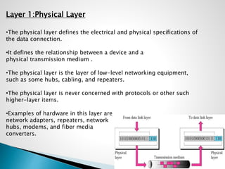
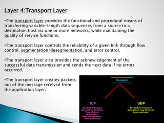
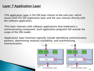
CONTENTS:
Introduction to OSI model
Layer 1-Physical Layer
Layer 2-Data Link Layer
Layer 3-Network Layer
Layer 4-Transport Layer
Layer 5-Session Layer
Layer 6-Presentation Layer
Layer 7-Application Layer
Introduction to OSI model
•The Open Systems Interconnection model (OSI model) is a conceptual
model that characterizes and standardizes the communication functions of
a telecommunication or computing system without regard to their
underlying internal structure and technology.
• Its goal is the interoperability of
diverse communication systems with
standard protocols.
•The model partitions a
communication system into
abstraction layers. The original
version of the model defined seven
layers.
Layer 1:Physical Layer
•The physical layer defines the electrical and physical specifications of
the data connection.
•It defines the relationship between a device and a
physical transmission medium .
•The physical layer is the layer of low-level networking equipment,
such as some hubs, cabling, and repeaters.
•The physical layer is never concerned with protocols or other such
higher-layer items.
•Examples of hardware in this layer are
network adapters, repeaters, network
hubs, modems, and fiber media
converters.
Layer 2:Data Link Layer
•The data link layer provides node-to-node data transfer—a link
between two directly connected nodes.
•It detects and possibly corrects errors that may occur in the physical
layer.
•It defines the protocol to establish and terminate a connection
between two physically connected devices.
•IEEE 802 divides the data link layer into two sublayers:
Media access control (MAC) layer – responsible for controlling
how devices in a network gain access to a medium and
permission to transmit data.
Logical link control (LLC) layer –
responsible for identifying and
encapsulating network layer
protocols, and controls error
checking and frame synchronization.
Layer 3:Network Layer
•The network layer provides the functional and procedural means of
transferring variable length data sequences (called datagrams) from
one node to another connected in "different networks“.
•Message delivery at the network layer is not necessarily guaranteed to
be reliable; a network layer protocol may provide reliable message
delivery, but it need not do so.
•A number of layer-management protocols belong to the network
layer. These include routing protocols, multicast group management,
network-layer information and error, and network-layer address
assignment.
Layer 4:Transport Layer
•The transport layer provides the functional and procedural means of
transferring variable-length data sequences from a source to a
destination host via one or more networks, while maintaining the
quality of service functions.
•The transport layer controls the reliability of a given link through flow
control, segmentation/desegmentation, and error control.
•The transport layer also provides the acknowledgement of the
successful data transmission and sends the next data if no errors
occurred.
•The transport layer creates packets
out of the message received from
the application layer.
Layer 5:Session Layer
•The session layer controls the dialogues (connections) between
computers. It establishes, manages and terminates the connections
between the local and remote application.
•It provides for full-duplex, half-duplex, or simplex operation, and
establishes checkpointing, adjournment, termination, and restart
procedures.
•The OSI model made this layer responsible for graceful close of
sessions, which is a property of the Transmission Control Protocol, and
also for session checkpointing and recovery, which is not usually used in
the Internet Protocol Suite.
•The session layer is commonly
implemented explicitly in
application environments that
use remote procedure calls.
Layer 6:Presentation Layer
•The presentation layer establishes context between application-layer entities,
in which the application-layer entities may use different syntax and semantics
if the presentation service provides a mapping between them.
•The presentation layer transforms data into the form that the application
accepts. This layer formats and encrypts data to be sent across a network.
•It is sometimes called the syntax layer.
•The original presentation structure used the Basic Encoding Rules of Abstract
Syntax Notation One (ASN.1), with capabilities such as converting an EBCDIC-
coded text file to an ASCII-coded file, or serialization of objects and other data
structures from and to XML.
Layer 7:Application Layer
•The application layer is the OSI layer closest to the end user, which
means both the OSI application layer and the user interact directly with
the software application.
•This layer interacts with software applications that implement a
communicating component. Such application programs fall outside the
scope of the OSI model.
•Application-layer functions typically include identifying communication
partners, determining resource availability, and synchronizing
communication.

Osi layer model

  • 2.
    CONTENTS: Introduction to OSImodel Layer 1-Physical Layer Layer 2-Data Link Layer Layer 3-Network Layer Layer 4-Transport Layer Layer 5-Session Layer Layer 6-Presentation Layer Layer 7-Application Layer
  • 3.
    Introduction to OSImodel •The Open Systems Interconnection model (OSI model) is a conceptual model that characterizes and standardizes the communication functions of a telecommunication or computing system without regard to their underlying internal structure and technology. • Its goal is the interoperability of diverse communication systems with standard protocols. •The model partitions a communication system into abstraction layers. The original version of the model defined seven layers.
  • 4.
    Layer 1:Physical Layer •Thephysical layer defines the electrical and physical specifications of the data connection. •It defines the relationship between a device and a physical transmission medium . •The physical layer is the layer of low-level networking equipment, such as some hubs, cabling, and repeaters. •The physical layer is never concerned with protocols or other such higher-layer items. •Examples of hardware in this layer are network adapters, repeaters, network hubs, modems, and fiber media converters.
  • 5.
    Layer 2:Data LinkLayer •The data link layer provides node-to-node data transfer—a link between two directly connected nodes. •It detects and possibly corrects errors that may occur in the physical layer. •It defines the protocol to establish and terminate a connection between two physically connected devices. •IEEE 802 divides the data link layer into two sublayers: Media access control (MAC) layer – responsible for controlling how devices in a network gain access to a medium and permission to transmit data. Logical link control (LLC) layer – responsible for identifying and encapsulating network layer protocols, and controls error checking and frame synchronization.
  • 6.
    Layer 3:Network Layer •Thenetwork layer provides the functional and procedural means of transferring variable length data sequences (called datagrams) from one node to another connected in "different networks“. •Message delivery at the network layer is not necessarily guaranteed to be reliable; a network layer protocol may provide reliable message delivery, but it need not do so. •A number of layer-management protocols belong to the network layer. These include routing protocols, multicast group management, network-layer information and error, and network-layer address assignment.
  • 7.
    Layer 4:Transport Layer •Thetransport layer provides the functional and procedural means of transferring variable-length data sequences from a source to a destination host via one or more networks, while maintaining the quality of service functions. •The transport layer controls the reliability of a given link through flow control, segmentation/desegmentation, and error control. •The transport layer also provides the acknowledgement of the successful data transmission and sends the next data if no errors occurred. •The transport layer creates packets out of the message received from the application layer.
  • 8.
    Layer 5:Session Layer •Thesession layer controls the dialogues (connections) between computers. It establishes, manages and terminates the connections between the local and remote application. •It provides for full-duplex, half-duplex, or simplex operation, and establishes checkpointing, adjournment, termination, and restart procedures. •The OSI model made this layer responsible for graceful close of sessions, which is a property of the Transmission Control Protocol, and also for session checkpointing and recovery, which is not usually used in the Internet Protocol Suite. •The session layer is commonly implemented explicitly in application environments that use remote procedure calls.
  • 9.
    Layer 6:Presentation Layer •Thepresentation layer establishes context between application-layer entities, in which the application-layer entities may use different syntax and semantics if the presentation service provides a mapping between them. •The presentation layer transforms data into the form that the application accepts. This layer formats and encrypts data to be sent across a network. •It is sometimes called the syntax layer. •The original presentation structure used the Basic Encoding Rules of Abstract Syntax Notation One (ASN.1), with capabilities such as converting an EBCDIC- coded text file to an ASCII-coded file, or serialization of objects and other data structures from and to XML.
  • 10.
    Layer 7:Application Layer •Theapplication layer is the OSI layer closest to the end user, which means both the OSI application layer and the user interact directly with the software application. •This layer interacts with software applications that implement a communicating component. Such application programs fall outside the scope of the OSI model. •Application-layer functions typically include identifying communication partners, determining resource availability, and synchronizing communication.