1
Network
Reference
Models
Network
Reference
Models
Computer Networks
Khaled Hussain
BSc. Hons. (BCU, UK) MSc. (BCU, UK)
CEO, Cybernetics Robo Academy
www.cyberneticsrobo.com
(Ex. Head, Dept. of Computer Science & Engineering, SIU)
Computer Networks
Khaled Hussain
BSc. Hons. (BCU, UK) MSc. (BCU, UK)
CEO, Cybernetics Robo Academy
www.cyberneticsrobo.com
(Ex. Head, Dept. of Computer Science & Engineering, SIU)
The Army puts out a bid on some computers and DEC wins the bid.
An Imaginary Story :)
The Air Force puts out a bid and IBM wins.
The Navy bid is won by Unisys.
Then the President decides to invade the ‘Land of the Giants’ and the armed
forces discover that their computers cannot talk to each other.
LAN Media
LAN Media
The OSI Model
 International standard organization (ISO) established a committee in
1977 to develop an architecture for computer communication.
 In 1984, the Open Systems Interconnection (OSI) reference model was
approved as an international standard for communications architecture.
 Initially, communication with different entities and different vendors was
extremely difficult as every vendor would have a different mechanism to
communicate.
 Hence, there arose a need to have a common, universally accepted
platform to communicate with entities of different vendor.
2
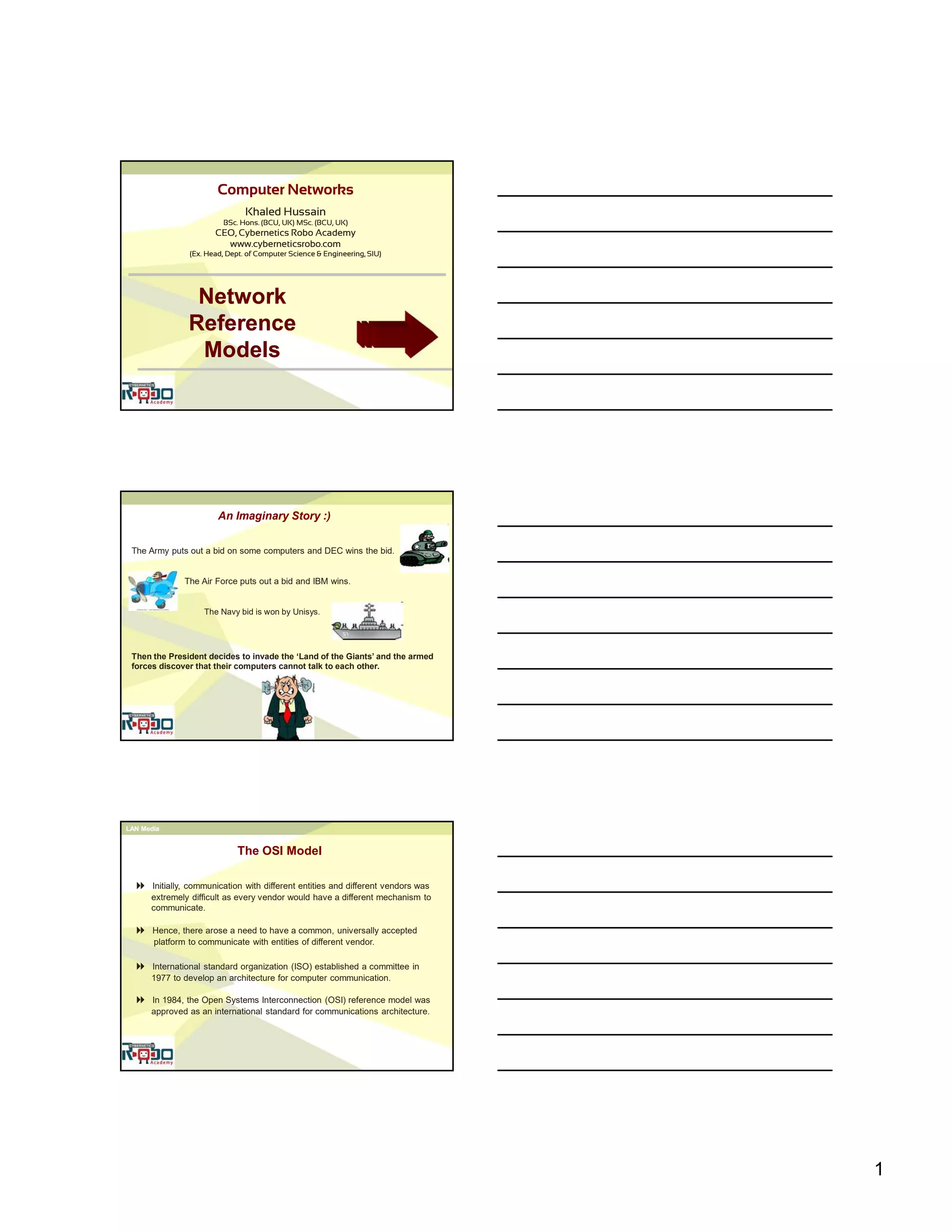
The OSI Model [continued]
 The OSI model describes how information or data makes its way from
application programs (such as spreadsheets) through a network medium
(such as wire) to another application program located on another
network.
 The OSI reference model divides the problem of moving information
between computers over a network medium into SEVEN smaller and
more manageable problems .
 The OSI (Open System Interconnection) is a layered framework of
network systems that allows communication between all types of
computer systems.
3
1. Physical Layer
 Characteristics such as voltage levels, timing of voltage changes,
physical data rates, representation of bits, physical connectors,
physical topologies and other similar attributes are defined by physical
layer specifications.
 Operates with data in the form of bits that are sent from the physical
layer of the sending (source) device and received at the physical
layer of the destination device.
 Defines all aspects of physical communication (mechanical, electrical,
functional etc.). It is responsible for the ultimate transmission of data
over network communications media.
 Protocol used : LLC
2. Data Link Layer
 The 0's and 1's that are used in the communication are grouped into
logical encapsulation called frames.
 Handle errors by implementing an acknowledgement and retransmission
scheme.
 Implement flow control.
 Data link layer attempts to provide reliable communication over the
physical layer interface.
 Protocol used : LLC
4
 The network layer is responsible for transportation of data across
multiple networks.
3. Network Layer
 Defines logical addressing so that any endpoint can be identified.
 Defines the most optimum path the packet should take from the
source to the destination
 Protocol used : IP, ARP, RARP
ICMP, IGMP
 Ensures quality and reliable mechanism for the exchange of data
between two processes in different computers.
4. Transport Layer
 Ensures that the data units are delivered error free.
 Data packet switching is entirely handled by the transport layer
 Ensures that there is no loss or duplication of data units.
 Protocol used : TCP, ARP, RARP, SPX, NWLINK, NETBIOS
 Provides mechanism for controlling the dialogue between the two end
systems. It defines how to start, control and end conversations (called
sessions) between applications.
5. Session Layer
 The applications that use RPC's (remote procedure calls) are taken care
of by the sessions layer
 Also provides check-pointing mechanism or synchronization points
such that if a failure of some sort occurs between checkpoints, all
data can be retransmitted from the last checkpoint.
 Any necessary log-on or password validation is also handled by this layer
 Protocol used : NETBIOS
5
 Defines the format in which the data is to be exchanged between the
communicating devices.
6. Presentation Layer
 Handles data compression and decompression
 Also handles data encryption / decryption (cryptography).
 Protocol used : SMB, NCP
 Topmost layer of the OSI reference model
7. Application Layer
 The application layer provides user interfaces and support for services
such as e-mail, remote file access and transfer, shared database
management and other types of distributed information services.
 Used for applications specifically written to run over the network
 Protocol used : DNS, FTP, TFTP, BOOTP, SNMP, SMTP
6
7
1. TCP/IP model was defined before the advent of the internet whereas OSI model
was defined after the advent of internet.
2. The OSI model consists of 7 architectural layers whereas the TCP/IP only
has 4 layers
3. OSI model is strictly layered whereas TCP/IP is loosely layered.
4. TCP/IP combines the presentation and session layer issues into its application
layer.
5. TCP/IP combines the OSI data link and physical layers into the network access
layer.
6. Transport layer in the OSI model guarantees data delivery whereas Transport
layer in the TCP/IP model supports data delivery without guarantee (e.g. UDP).
7. OSI is a reference model and TCP/IP is an implementation of OSI model.
8. TCP/IP Protocols are considered to be standards around which the internet
has developed. The OSI model however is a "generic, protocol-independent
standard."
Differences between the OSI and TCP/IP model
Types of Addresses used in TCP/IP
Addresses
Physical
Addresses
Logical
Addresses
Port
Addresses
Specific
Addresses
Relationship of layers and addresses in TCP/IP
8
 The Lowest level address included in the frame used by the data link
layer
Physical Address
 Most LAN use a 48 bit (6 byte) physical address written in 12
hexadecimal digits that is imprinted on the Network Interface Card (NIC).
07:01:02:01:2C:4B
A 6-byte (12 hexadecimal digits) physical address.
 A universal addressing system in which each host can be identified
uniquely regardless of the underlying physical network.
Logical Address
 A logical address is currently a 32 bit address that can uniquely define a
host connected to the internet.
241.177.15.2
 A computer runs many different processes at the same time.
Port Address
 Port numbers allow different applications on the same computer to share
network resources simultaneously. Port numbers are associated with
network addresses.
9
 Some applications have user-friendly addresses designed for that specific
address (e.g. e-mail addresses, URLs etc.)
Specific Address
 These addresses, however, get changed to the corresponding port and
logical addresses by the sending computer.
Read section 2.5 (Forouzan) on addresses
Sources & References
 http://encyclopedia2.thefreedictionary.com/OSI+model
 Yale University, USA
web : www.yale.edu/pclt/COMM/TCPIP.html
 Forouzan B.A, Data Communications and Networking, 4th edition
 University of East London
web : http://homepages.uel.ac.uk/u9703493/comparison.htm
 Tanenbaum A.S., Computer Networks, 4th edition
 http://compnetworking.about.com/od/basicnetworkingconcepts/l/blbasics_osi1.htm
 Lecture notes, Indian Institute of Technology (IIT) Kanpur, India.

Network Reference Model (Computer Networks) - Cybernetics Robo Academy

  • 1.
    1 Network Reference Models Network Reference Models Computer Networks Khaled Hussain BSc.Hons. (BCU, UK) MSc. (BCU, UK) CEO, Cybernetics Robo Academy www.cyberneticsrobo.com (Ex. Head, Dept. of Computer Science & Engineering, SIU) Computer Networks Khaled Hussain BSc. Hons. (BCU, UK) MSc. (BCU, UK) CEO, Cybernetics Robo Academy www.cyberneticsrobo.com (Ex. Head, Dept. of Computer Science & Engineering, SIU) The Army puts out a bid on some computers and DEC wins the bid. An Imaginary Story :) The Air Force puts out a bid and IBM wins. The Navy bid is won by Unisys. Then the President decides to invade the ‘Land of the Giants’ and the armed forces discover that their computers cannot talk to each other. LAN Media LAN Media The OSI Model  International standard organization (ISO) established a committee in 1977 to develop an architecture for computer communication.  In 1984, the Open Systems Interconnection (OSI) reference model was approved as an international standard for communications architecture.  Initially, communication with different entities and different vendors was extremely difficult as every vendor would have a different mechanism to communicate.  Hence, there arose a need to have a common, universally accepted platform to communicate with entities of different vendor.
  • 2.
    2 The OSI Model[continued]  The OSI model describes how information or data makes its way from application programs (such as spreadsheets) through a network medium (such as wire) to another application program located on another network.  The OSI reference model divides the problem of moving information between computers over a network medium into SEVEN smaller and more manageable problems .  The OSI (Open System Interconnection) is a layered framework of network systems that allows communication between all types of computer systems.
  • 3.
    3 1. Physical Layer Characteristics such as voltage levels, timing of voltage changes, physical data rates, representation of bits, physical connectors, physical topologies and other similar attributes are defined by physical layer specifications.  Operates with data in the form of bits that are sent from the physical layer of the sending (source) device and received at the physical layer of the destination device.  Defines all aspects of physical communication (mechanical, electrical, functional etc.). It is responsible for the ultimate transmission of data over network communications media.  Protocol used : LLC 2. Data Link Layer  The 0's and 1's that are used in the communication are grouped into logical encapsulation called frames.  Handle errors by implementing an acknowledgement and retransmission scheme.  Implement flow control.  Data link layer attempts to provide reliable communication over the physical layer interface.  Protocol used : LLC
  • 4.
    4  The networklayer is responsible for transportation of data across multiple networks. 3. Network Layer  Defines logical addressing so that any endpoint can be identified.  Defines the most optimum path the packet should take from the source to the destination  Protocol used : IP, ARP, RARP ICMP, IGMP  Ensures quality and reliable mechanism for the exchange of data between two processes in different computers. 4. Transport Layer  Ensures that the data units are delivered error free.  Data packet switching is entirely handled by the transport layer  Ensures that there is no loss or duplication of data units.  Protocol used : TCP, ARP, RARP, SPX, NWLINK, NETBIOS  Provides mechanism for controlling the dialogue between the two end systems. It defines how to start, control and end conversations (called sessions) between applications. 5. Session Layer  The applications that use RPC's (remote procedure calls) are taken care of by the sessions layer  Also provides check-pointing mechanism or synchronization points such that if a failure of some sort occurs between checkpoints, all data can be retransmitted from the last checkpoint.  Any necessary log-on or password validation is also handled by this layer  Protocol used : NETBIOS
  • 5.
    5  Defines theformat in which the data is to be exchanged between the communicating devices. 6. Presentation Layer  Handles data compression and decompression  Also handles data encryption / decryption (cryptography).  Protocol used : SMB, NCP  Topmost layer of the OSI reference model 7. Application Layer  The application layer provides user interfaces and support for services such as e-mail, remote file access and transfer, shared database management and other types of distributed information services.  Used for applications specifically written to run over the network  Protocol used : DNS, FTP, TFTP, BOOTP, SNMP, SMTP
  • 6.
  • 7.
    7 1. TCP/IP modelwas defined before the advent of the internet whereas OSI model was defined after the advent of internet. 2. The OSI model consists of 7 architectural layers whereas the TCP/IP only has 4 layers 3. OSI model is strictly layered whereas TCP/IP is loosely layered. 4. TCP/IP combines the presentation and session layer issues into its application layer. 5. TCP/IP combines the OSI data link and physical layers into the network access layer. 6. Transport layer in the OSI model guarantees data delivery whereas Transport layer in the TCP/IP model supports data delivery without guarantee (e.g. UDP). 7. OSI is a reference model and TCP/IP is an implementation of OSI model. 8. TCP/IP Protocols are considered to be standards around which the internet has developed. The OSI model however is a "generic, protocol-independent standard." Differences between the OSI and TCP/IP model Types of Addresses used in TCP/IP Addresses Physical Addresses Logical Addresses Port Addresses Specific Addresses Relationship of layers and addresses in TCP/IP
  • 8.
    8  The Lowestlevel address included in the frame used by the data link layer Physical Address  Most LAN use a 48 bit (6 byte) physical address written in 12 hexadecimal digits that is imprinted on the Network Interface Card (NIC). 07:01:02:01:2C:4B A 6-byte (12 hexadecimal digits) physical address.  A universal addressing system in which each host can be identified uniquely regardless of the underlying physical network. Logical Address  A logical address is currently a 32 bit address that can uniquely define a host connected to the internet. 241.177.15.2  A computer runs many different processes at the same time. Port Address  Port numbers allow different applications on the same computer to share network resources simultaneously. Port numbers are associated with network addresses.
  • 9.
    9  Some applicationshave user-friendly addresses designed for that specific address (e.g. e-mail addresses, URLs etc.) Specific Address  These addresses, however, get changed to the corresponding port and logical addresses by the sending computer. Read section 2.5 (Forouzan) on addresses Sources & References Sources & References  http://encyclopedia2.thefreedictionary.com/OSI+model  Yale University, USA web : www.yale.edu/pclt/COMM/TCPIP.html  Forouzan B.A, Data Communications and Networking, 4th edition  University of East London web : http://homepages.uel.ac.uk/u9703493/comparison.htm  Tanenbaum A.S., Computer Networks, 4th edition  http://compnetworking.about.com/od/basicnetworkingconcepts/l/blbasics_osi1.htm  Lecture notes, Indian Institute of Technology (IIT) Kanpur, India.