ORIFICE METER
DEFINITION:
The orificeplate is a differential pressure flow meter (Primary
element).
The velocity of fluid passing through the orifice is proportional to
the square root of the pressure loss across it.
WORKING PRINCIPLE:
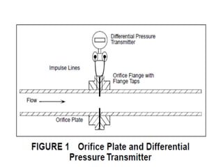
To measure the differential pressure when the fluid is flowing,
connections are made from the upstream and downstream
pressure tappings to a secondary device known as a DP
(Differential Pressure) cell
3.
INTRODUCTION –ORIFICE METER
AnOrifice flow meter is the most common head type flow
measuring device.
It is inserted in the pipeline and the differential pressure across it is
measured.
Construction details:
It consist of a metal plate with a concentric round hole (orifice)
through which the liquid flows.
An integral metal tab facilitates installation and carries details of
the plate size, thickness, serial number, etc.
4.
The plate, usuallymanufactured from stainless steel, Monel, or
phosphor bronze, should be of sufficient thickness to withstand
buckling (3 - 6 mm).
The orifice plate is inserted into the main pipeline between
adjacent flanges, the outside diameters of the plate being turned
to fit within the flange bolts.
The flanges are either screwed or welded to the pipes
5.
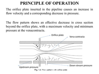
PRINCIPLE OF OPERATION
Theorifice plate inserted in the pipeline causes an increase in
flow velocity and a corresponding decrease in pressure.
The flow pattern shows an effective decrease in cross section
beyond the orifice plate, with a maximum velocity and minimum
pressure at the venacontracta.
Orifice plate
Vena contracta
Upstream pressure
Down stream pressure
6.
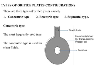
TYPES OF ORIFICEPLATES CONFIGURATIONS
There are three types of orifice plates namely
1. Concentric type 2. Eccentric type 3. Segmental type.
Concentric type
The most frequently used type.
The concentric type is used for
clean fluids.
Round metal sheet
SS, Bronze,Ceramic,
Phospor etc
7.
TYPES OF ORIFICEPLATES CONFIGURATIONS
2.Eccentric type
The orifice is usually set at the bottom of the pipe bore.
Eccentrically bored orifice plates are plates with the orifice off-center,
or eccentric, as opposed to concentric.
This configuration is mainly used where the fluid contains heavy
solids (like dirty fluids, slurries ) that become trapped and accumulate
on the backside of the plate.
With the orifice set at the bottom, these solids are easily allowed to
pass.
Ie these plates are used to measure the flow of vapours (that carry
small amounts of liquids) or gases (condensed vapours), since the
liquids will carry through the opening at the bottom of the pipe.
8.
TYPES OF ORIFICEPLATES CONFIGURATIONS
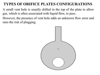
A small vent hole is usually drilled in the top of the plate to allow
gas, which is often associated with liquid flow, to pass.
However, the presence of vent hole adds an unknown flow error and
runs the risk of plugging.
9.
TYPES OF ORIFICEPLATES CONFIGURATIONS
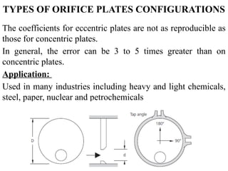
The coefficients for eccentric plates are not as reproducible as
those for concentric plates.
In general, the error can be 3 to 5 times greater than on
concentric plates.
Application:
Used in many industries including heavy and light chemicals,
steel, paper, nuclear and petrochemicals
10.
TYPES OF ORIFICEPLATES CONFIGURATIONS
3.Segmental type
The opening in a segmental
orifice plate is a circular
segment – comparable to a
partially opened gate valve.
The segmental opening may be
placed either at the top or
bottom of the pipe.
This plate is generally employed
for measuring liquids or gases
that carry non-abrasive
impurities - light slurries, dirty
gases.
Vent
Segmental
bore
PRESSURE TAPS LOCATIONS
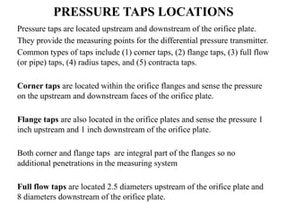
Pressuretaps are located upstream and downstream of the orifice plate.
They provide the measuring points for the differential pressure transmitter.
Common types of taps include (1) corner taps, (2) flange taps, (3) full flow
(or pipe) taps, (4) radius tapes, and (5) contracta taps.
Corner taps are located within the orifice flanges and sense the pressure
on the upstream and downstream faces of the orifice plate.
Flange taps are also located in the orifice plates and sense the pressure 1
inch upstream and 1 inch downstream of the orifice plate.
Both corner and flange taps are integral part of the flanges so no
additional penetrations in the measuring system
Full flow taps are located 2.5 diameters upstream of the orifice plate and
8 diameters downstream of the orifice plate.
14.
PRESSURE TAPS LOCATIONS
Radiustaps are located 1 diameter upstream and 0.5 diameters
downstream of the orifice plate.
Vena contracta taps are located 1 diameter upstream of the orifice and
at the point downstream where there is the lowest static pressure, the
vena contracta.
The point downstream where the pressure is the lowest is dependent on
the type of orifice plate and the beta ratio.
The discharge coefficient is dependent on the type of orifice and the tap
location.
When dealing with flowmeters, this constant is most often referred to as
the K factor.
15.
PRESSURE TAPS LOCATIONS
TheK factor is typically given in units of pulses/gallons.
The constancy of the K factor is what determines the accuracy of
the flowmeter.
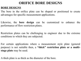
ORIFICE BORE DESIGNS
BOREDESIGNS
The bore in the orifice plate can be shaped or positioned to create
advantages for specific measurement applications.
Likewise, the bore design can be customized to enhance the
performance of flow restriction plates.
Restriction plates can be challenging to engineer due to the extreme
conditions to which they are subjected.
For certain applications where a measurement style plate (general
purpose) is not suitable then, a “thick” restriction plate or a multi-
stage plate may be used.
A thick plate is as thick as the diameter of the bore.
18.
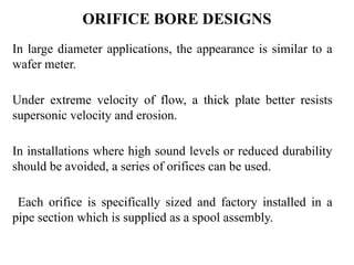
ORIFICE BORE DESIGNS
Inlarge diameter applications, the appearance is similar to a
wafer meter.
Under extreme velocity of flow, a thick plate better resists
supersonic velocity and erosion.
In installations where high sound levels or reduced durability
should be avoided, a series of orifices can be used.
Each orifice is specifically sized and factory installed in a
pipe section which is supplied as a spool assembly.
19.
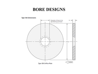
BORE DESIGNS
TYPES OFBORE DESIGNS
Square Egde
Quadrant edge
Paddle type edge
Special type (1) Thick restriction bore
(2) Conical restriction bore
BORE DESIGNS- SQUAREEDGE
For the common square edge
concentric bore orifice, the bore and
bevel is the standard method of
limiting the plate edge thickness.
Unless otherwise specified, plates
will be beveled to the current
accepted AGA standards.
BORE DESIGNS- QUADRANTEDGE
The quadrant edge bore is an orifice with the inlet edge rounded.
Instead of beveling, the plate is counterbored to the desired edge
thickness.
The radius of the quartercircle bore is a function of the orifice-to-pipe
ratio (d/D).
Thickness at the throat is equal to the radius.
This bore is specifically designed for viscous fluids such as heavy
crudes, syrups, and slurries with Reynolds Numbers below 100,000
BORE DESIGNS- SPECIALTYPE
Thick restriction bore are designed with the assumption for
application like when the fluids will reach sonic velocity through
the bore of the restriction (critical flow).
Design the thick plate that can withstand the mechanical wear
associated with sonic velocity.
27.
BORE DESIGNS- SPECIALTYPE
The conical orifice bore is a measurement orifice installed
in the flow line with the bevel facing upstream.
This type is highly suitable for low Reynolds Number
applications.
Due to reduced machining, this style is more economical
than the quadrant bore typically used for measurement of
viscous fluids, and is sufficiently accurate for most
restriction applications
BORE DESIGNS- SPECIALTYPE
MULTI STAGE OR METER
A multi-plate restriction assembly reduces the flowing pressure in
stages as a means of reducing noise pollution or improving the
durability of the restriction element.
Flow is kept subsonic and non-cavitating at each stage by adding
stages.
Each assembly is custom-engineered by for specific operating
parameters.
Most assemblies are welded with non-removable plates.
These assemblies are commonly used in “blowdown”
applications in which gases are vented to atmospheric pressure
with minimal emitted sound
30.
ORIFICE PLATES –GENERAL
Advantages
Simple construction.
Inexpensive.
Robust
Easily fitted between flanges.
No moving parts.
Large range of sizes and opening ratios.
Suitable for most gases and liquids as well as steam.
Price does not increase dramatically with size.
Well understood and proven.
31.
ORIFICE PLATES –GENERAL
Disadvantages
Permanent pressure loss of head is quite high.
Inaccuracy, typically 2 to 3%.
Low turndown ratio, typically from 3 to 4:1.
Accuracy is affected by density, pressure and viscosity
fluctuations.
Erosion and physical damage to the restriction affects
measurement accuracy.
Viscosity limits measuring range.
Requires straight pipe runs to ensure accuracy is maintained.
Pipeline must be full (typically for liquids).
Output is not linearly related to flowrate.
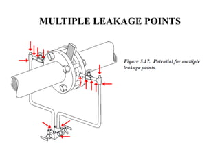
Multiple potential leakage points
32.
STRAIGHT PIPE RUNREQUIREMENTS
The inaccuracy with orifice type measurement is due mainly to
process conditions and temperature and pressure variations.
Ambient conditions and upstream and downstream piping also affect
the accuracy because of changes to the pressure and continuity of
flow.
The need for straight runs of piping both before and after the orifice
plate flow element is rarely met – often through ignorance.
Without flow-straightening, a typical installation requires from 25 to
40D (pipe diameters) of straight run piping before the element and
about 4 or 5D downstream of the element.
33.
STRAIGHT PIPE RUNREQUIREMENTS
These requirements vary quite considerably according to the
upstream (and downstream) discontinuities and the beta ratio.
Typically:
β ratio of 0.5: 25 pipe diameters upstream and (25 D) and 4
pipe diameters downstream (4D).
β ratio of 0.7: 40 D upstream and 5 D downstream.
The requirements for custody transfer applications are
considerably
ORICE PLATE THICKNESS
Asthe differential pressure across the orifice increases, the plate
tends to deform elastically and, beyond a certain point, the
deformation results in a shift in the meter characteristics and
an increase in the measurement uncertainty.
The thickness of an orifice plate should thus be sufficient to
ensure that the deflection does not exceed certain limits.
The thickness is generally determined according to the guidelines
given by ISO-5167; ISA-RP-3.2; API-2530; and ASME-MFC-
3M.
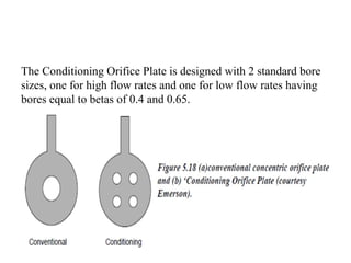
CONDITIONING OF ORIFICEPLATES
The ‘Conditioning Orifice Plate’ introduced several years ago by
Emerson overcomes the problem of upstream disturbances that
cause swirl in a pipe and create an irregular flow profile.
In a conventional concentric orifice plate these effects are
amplified, allowing the disturbance to impact measurement.
The ‘Conditioning Orifice Plate’ is a differential pressure
producer that differs from the conventional orifice plate in using
four equally spaced holes that are arranged in such a fashion as to
leave a metal section of the plate in the center of the pipe.
This causes the flow to condition itself as it is forced through the
four holes – thus eliminating swirl and irregular flow profiles and
removing the requirement for a flow conditioner.
39.
CONDITIONING ORIFICE PLATE
Theconsequence of this arrangement is that the straight-run
requirements are reduced to only 2 upstream and 2 downstream
pipe diameters.
Furthermore, the discharge coefficient (Cd) is reduced to ± 0.5%.
A further benefit is that the four-hole design minimizes liquid
hold-up, as compared with a standard orifice plate, without the
need for an accuracy-reducing and plugging-prone vent hole.
The sum of the area of the four bores is equivalent to the area of
a bore ‘d’ in the standard equation:
β = d/D for a schedule standard pipe.
40.
The Conditioning OrificePlate is designed with 2 standard bore
sizes, one for high flow rates and one for low flow rates having
bores equal to betas of 0.4 and 0.65.