Downloaded 108 times


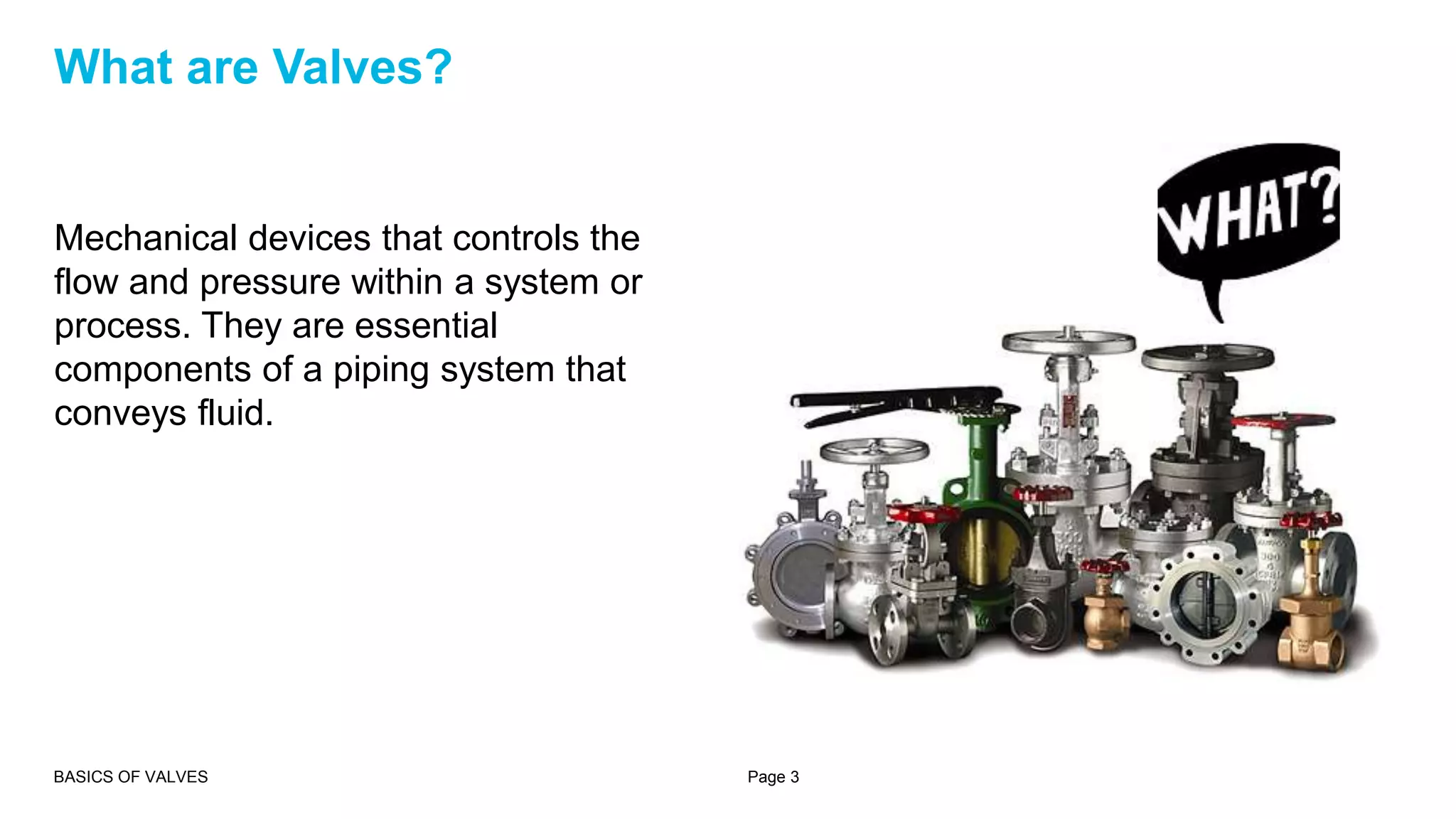
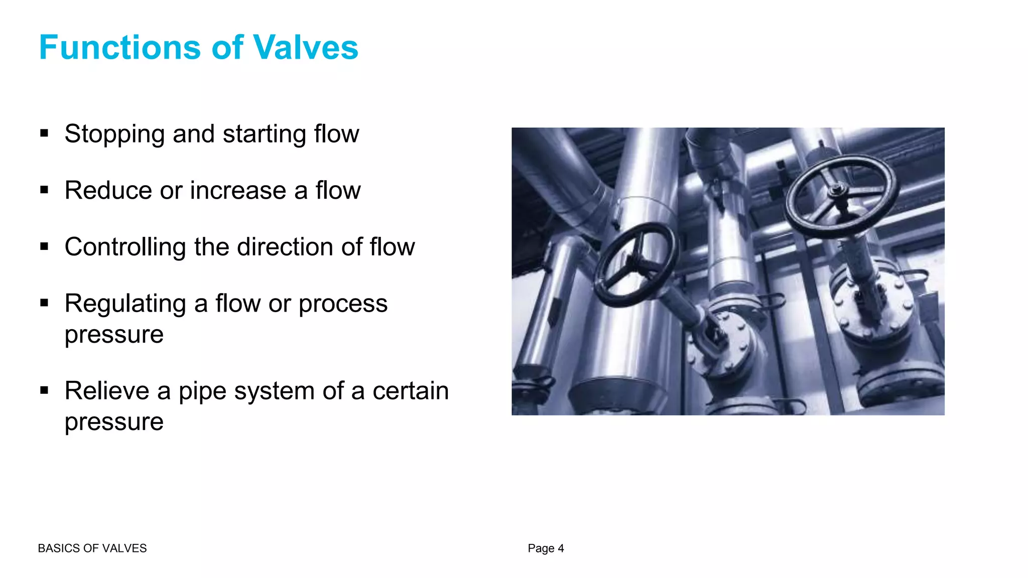
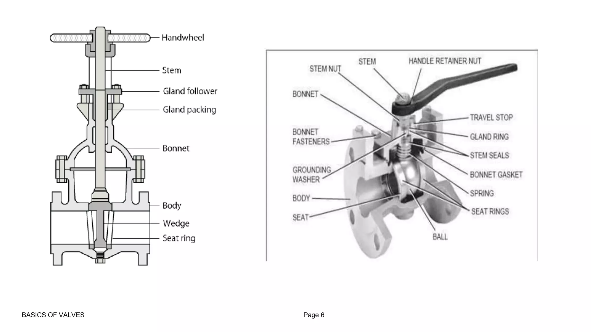

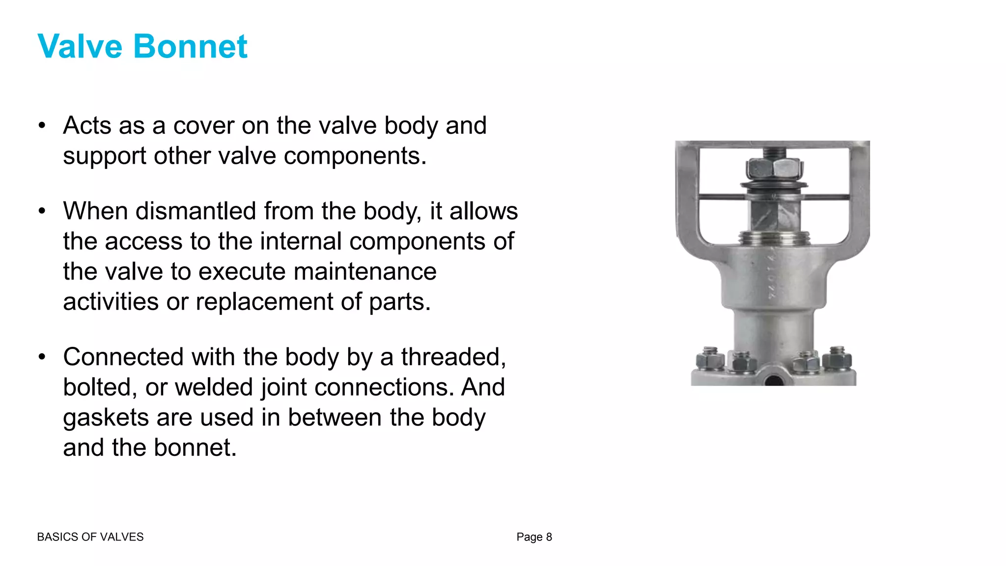


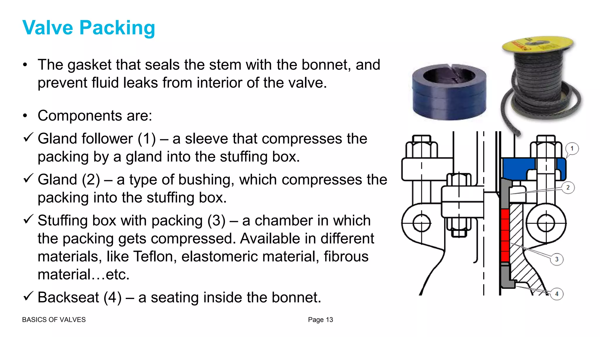


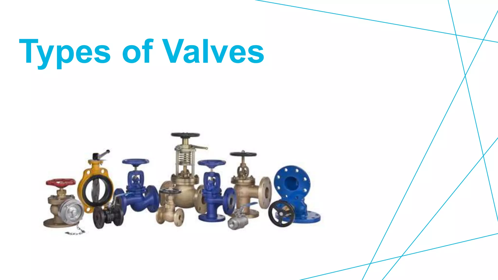
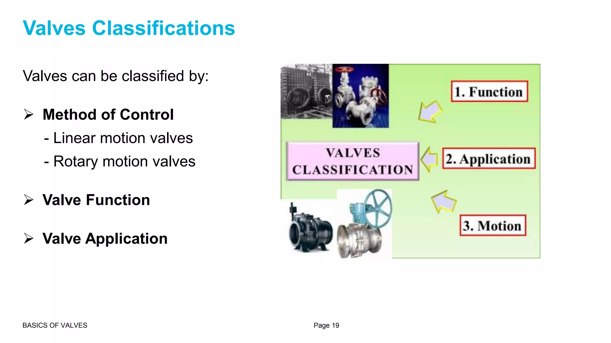
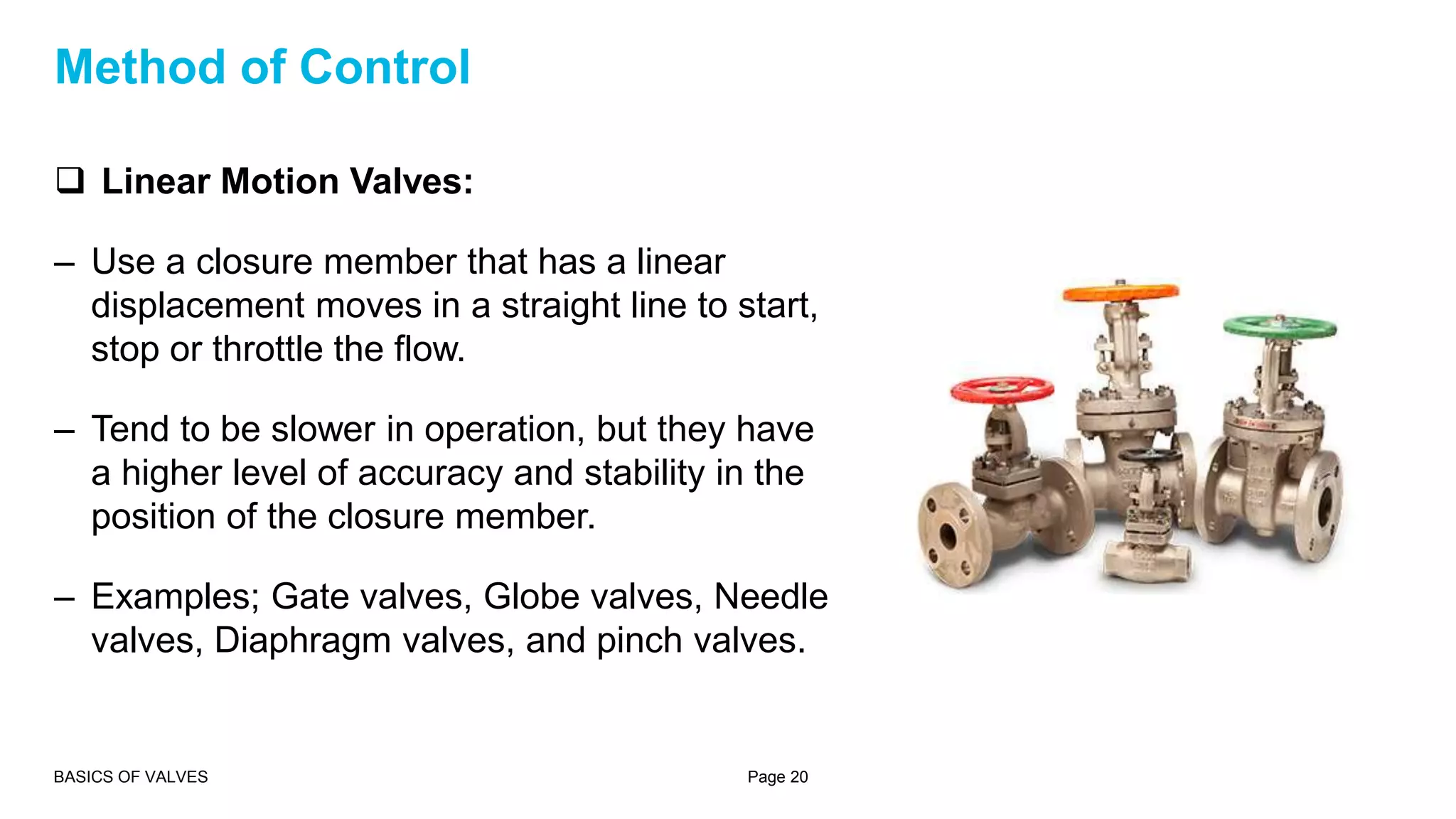

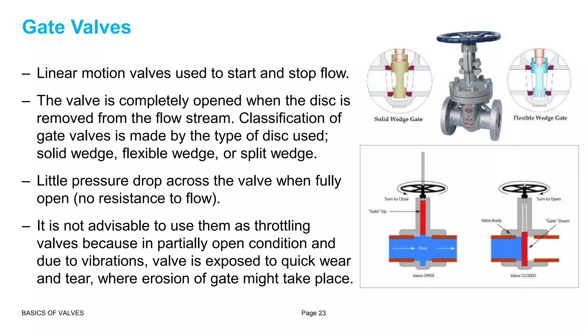
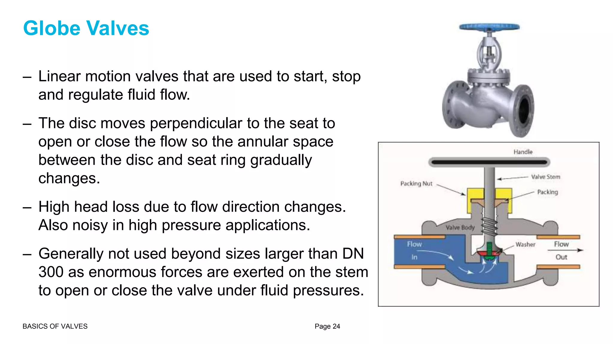

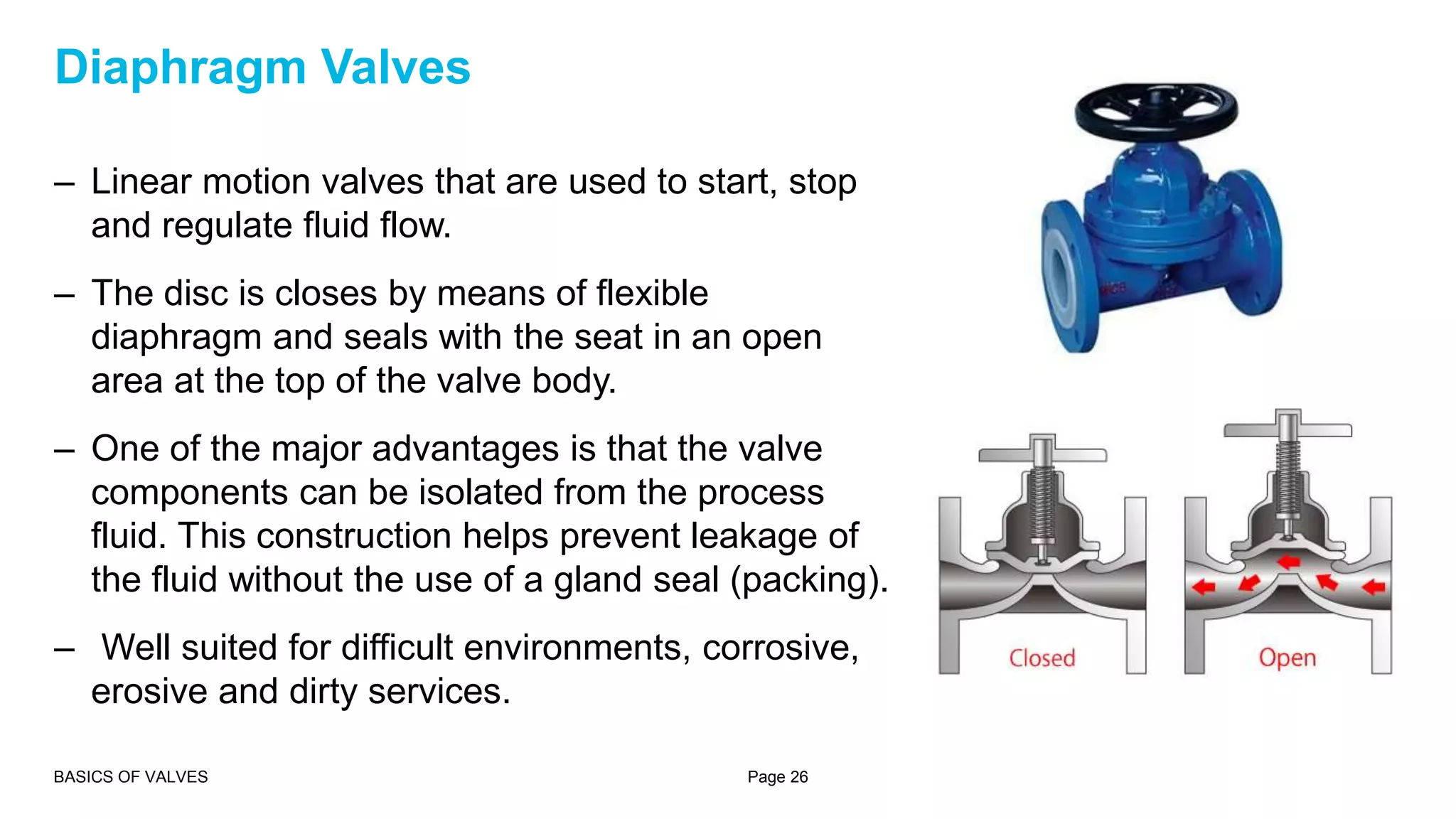
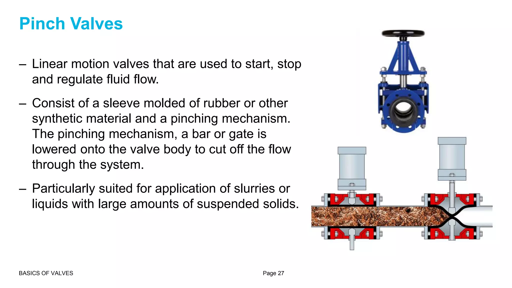
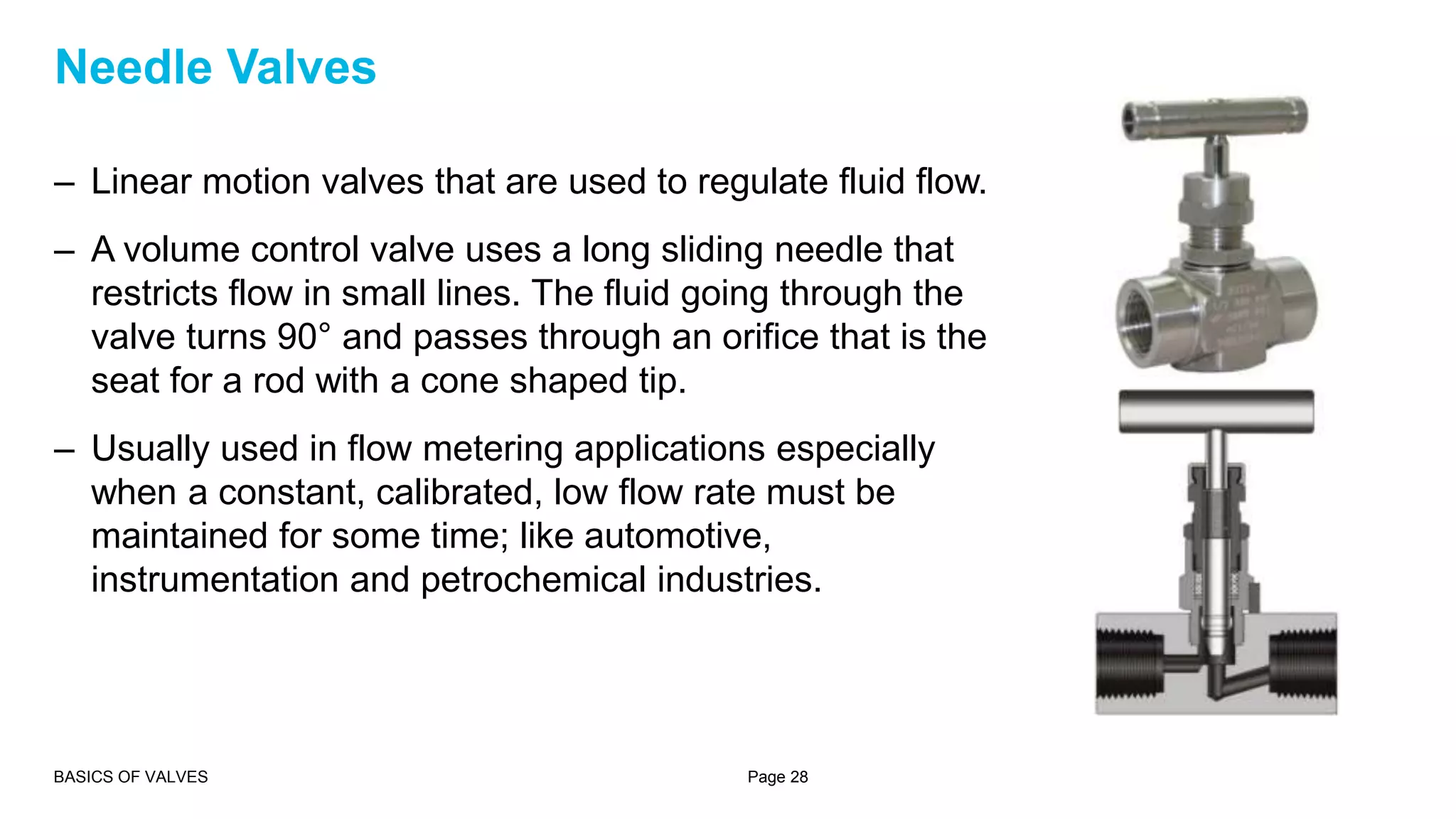
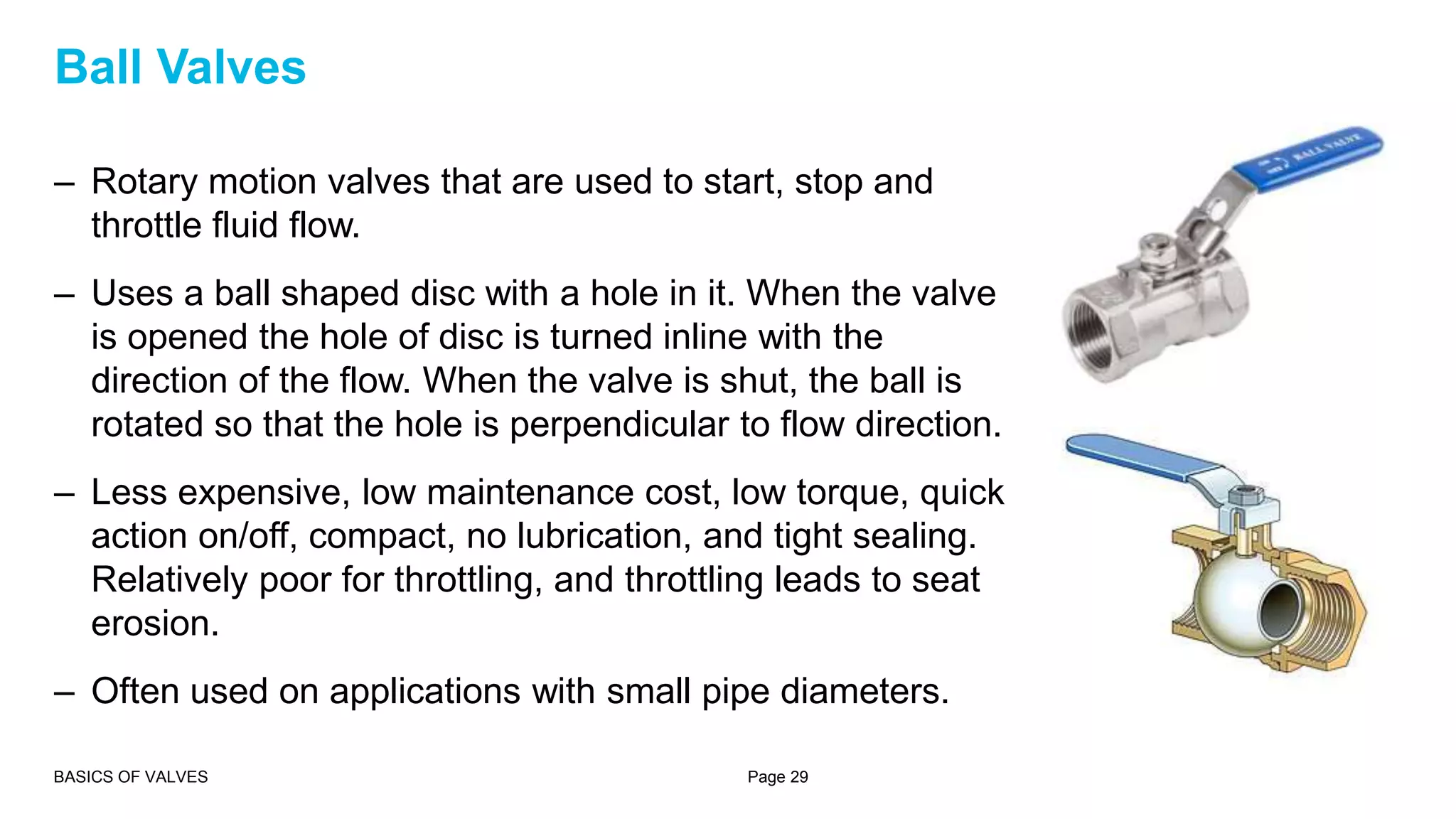

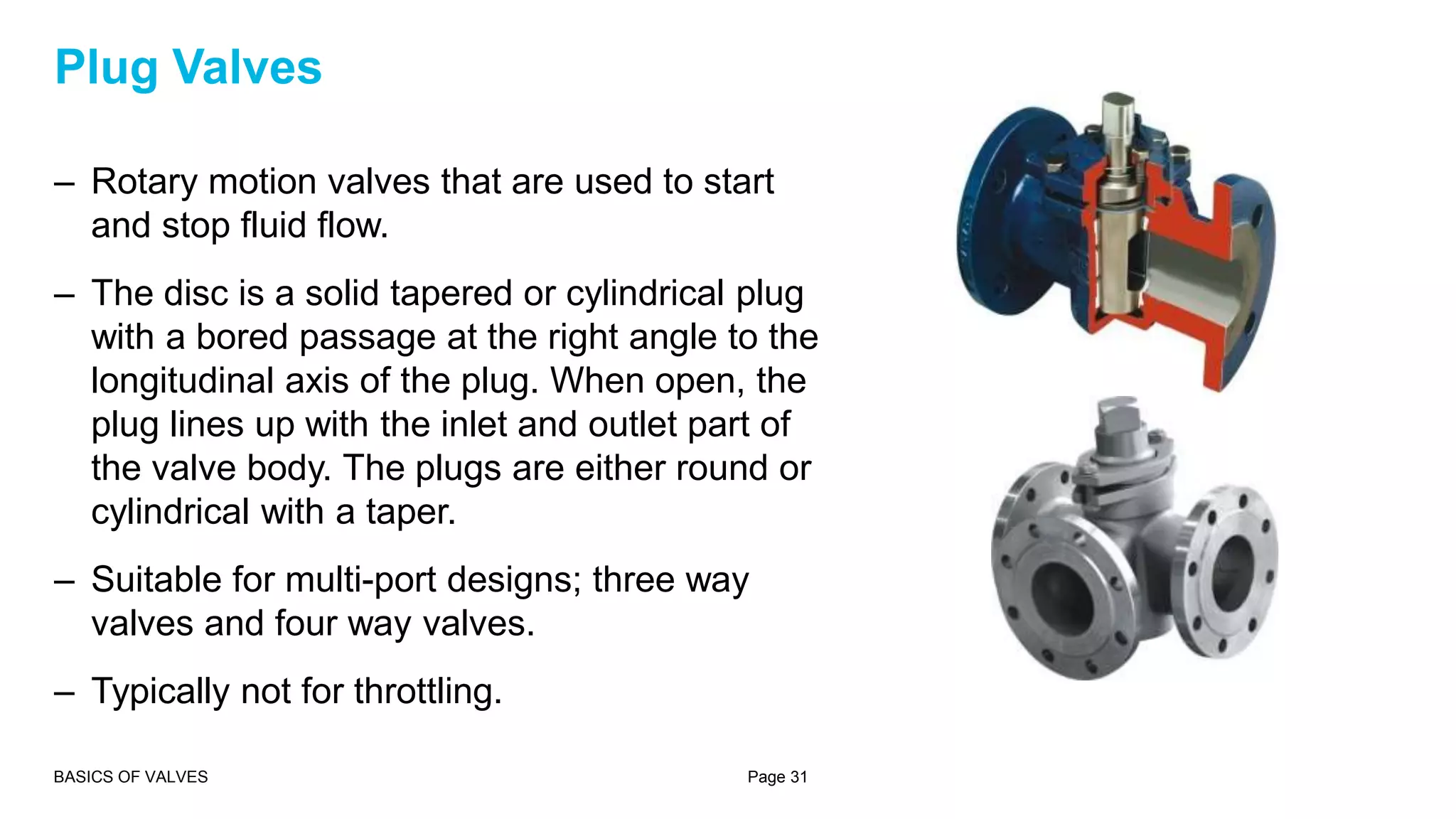


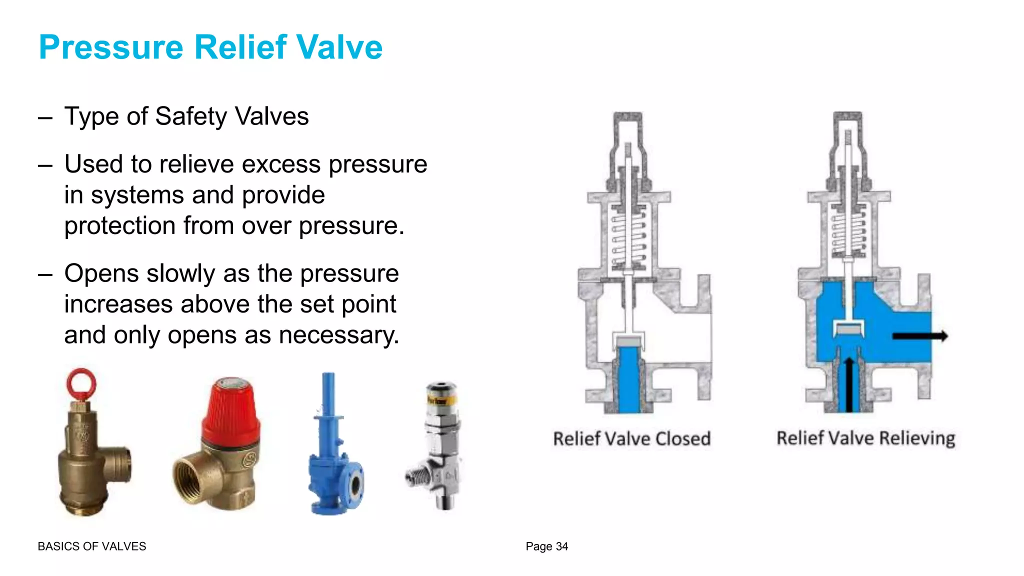

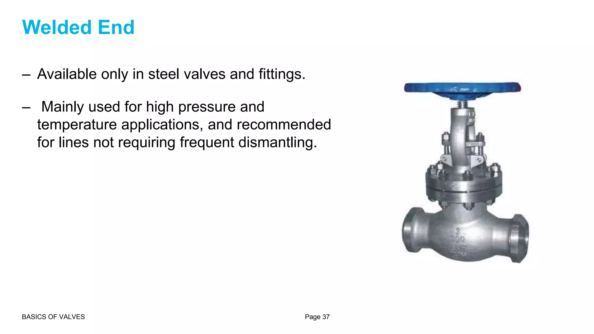


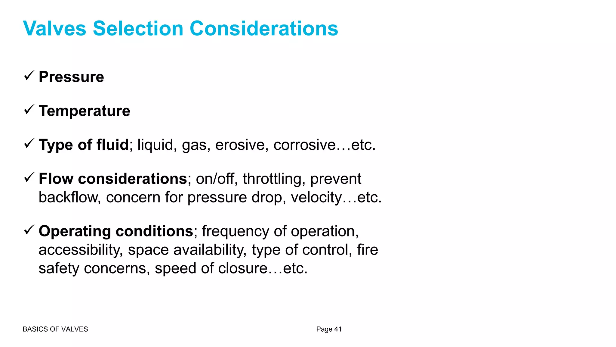


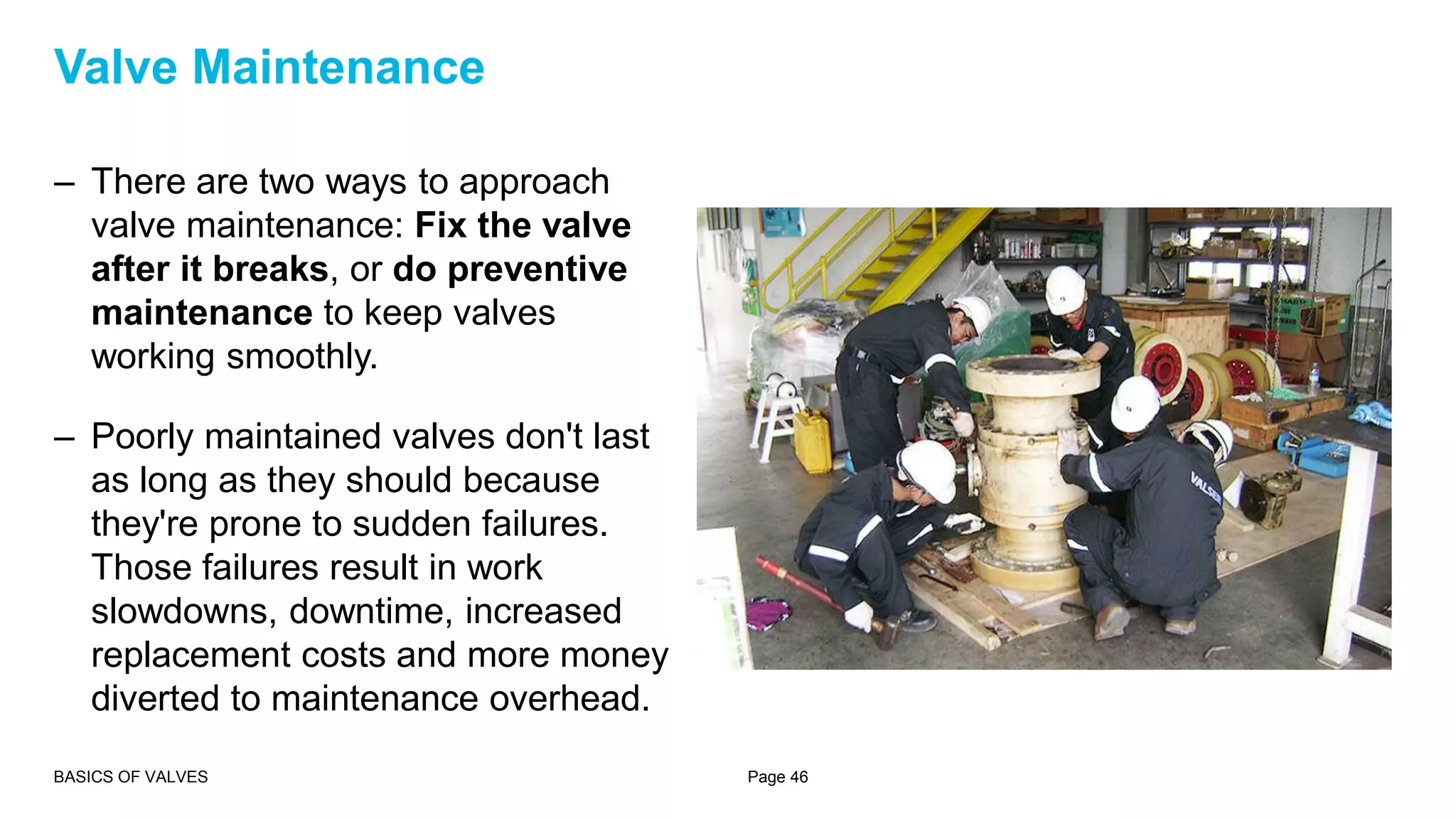


Valves are mechanical devices that control the flow and pressure within a system. They have common parts like a body, bonnet, trim, disc, seats, and stem. Valves come in different types defined by their motion (linear or rotary) and function (starting/stopping flow, throttling, or preventing backflow). Proper selection and maintenance of valves is important for system performance and reliability. Valve maintenance includes cleaning, inspection, and scheduled repairs or replacement of worn parts.


