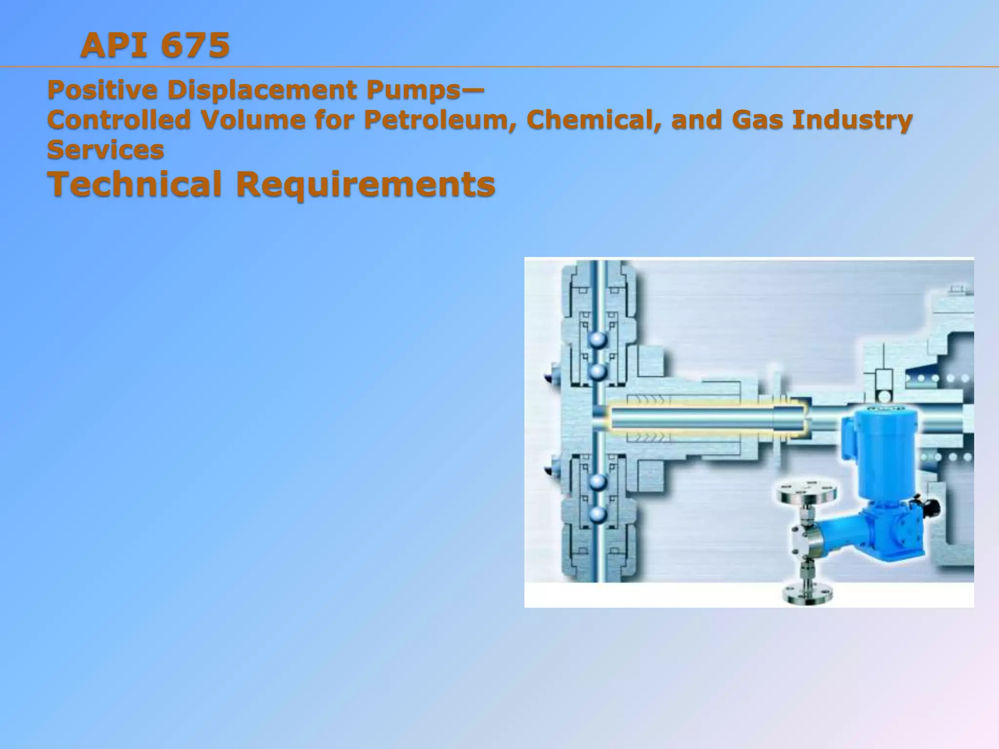
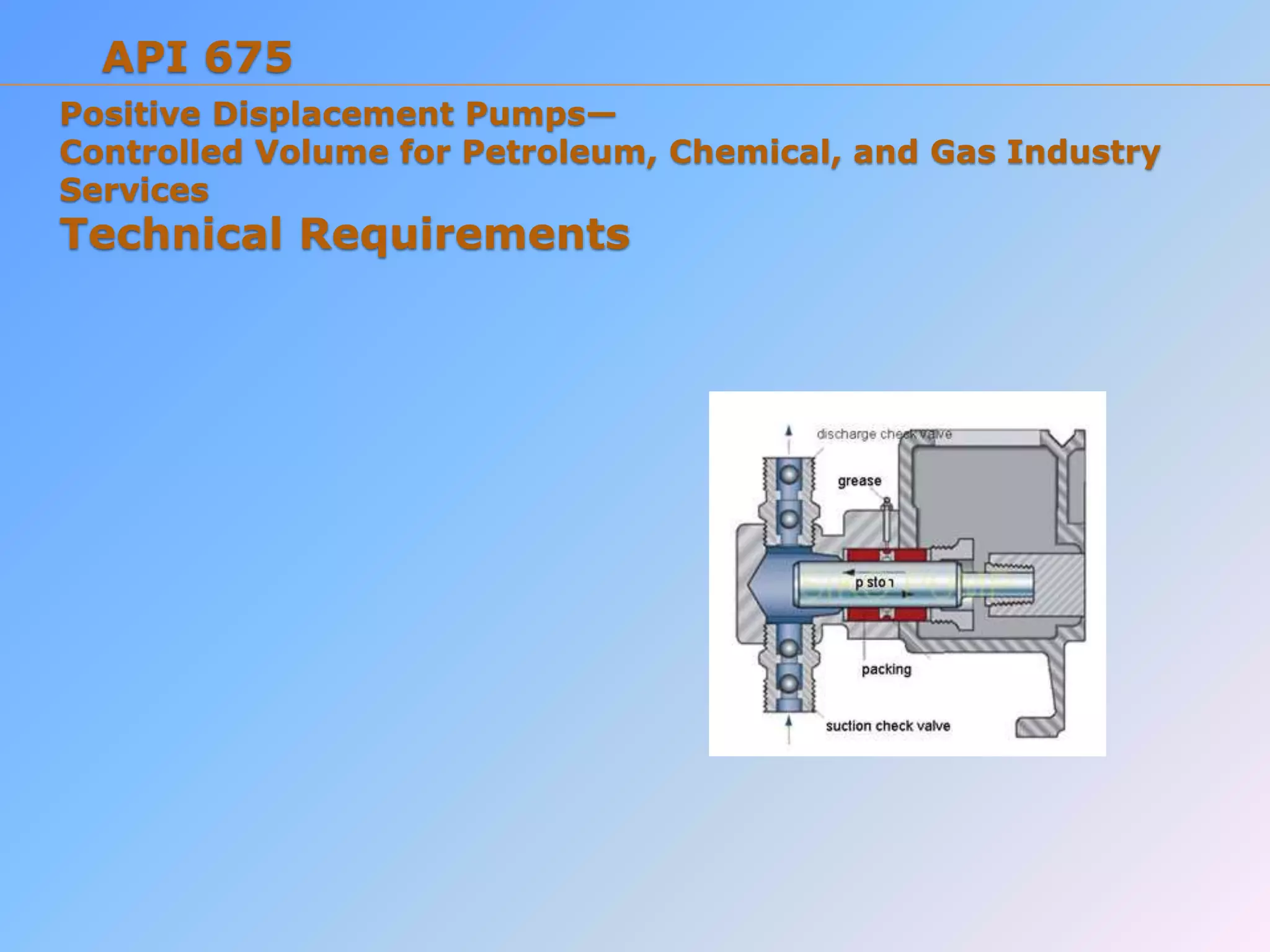
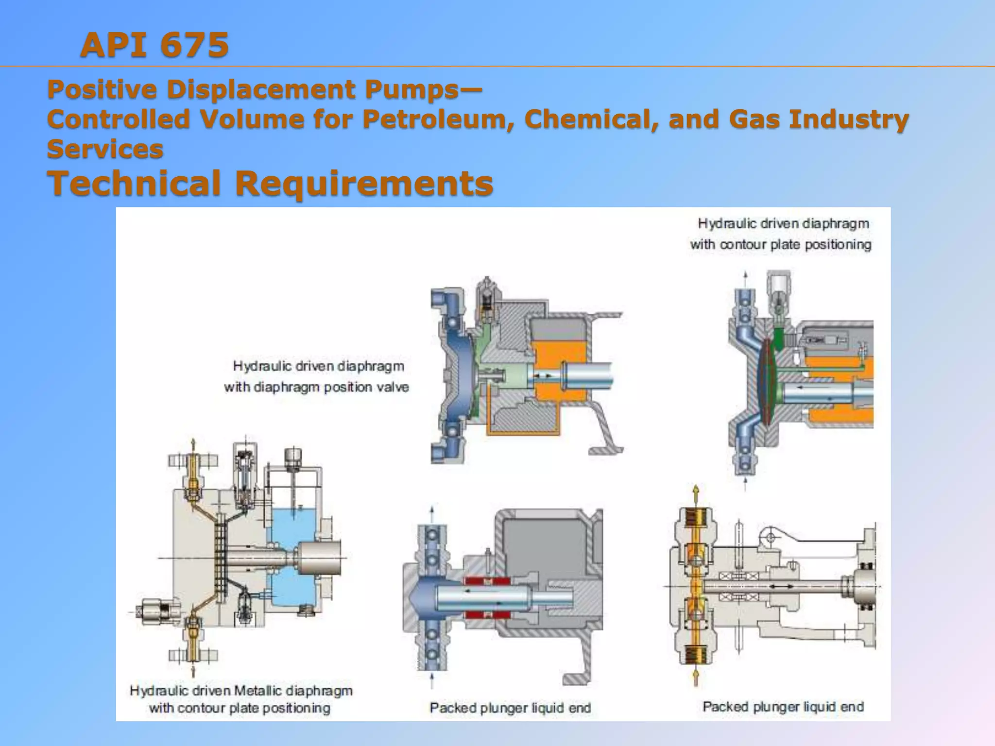
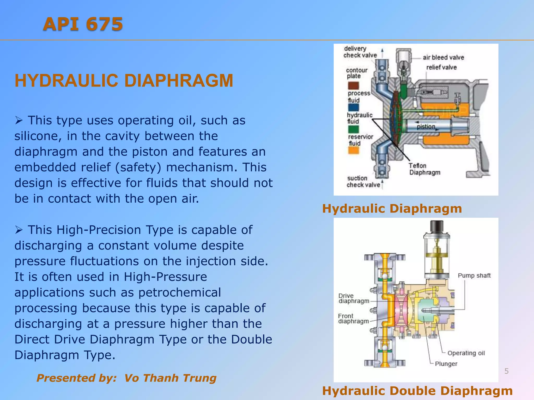
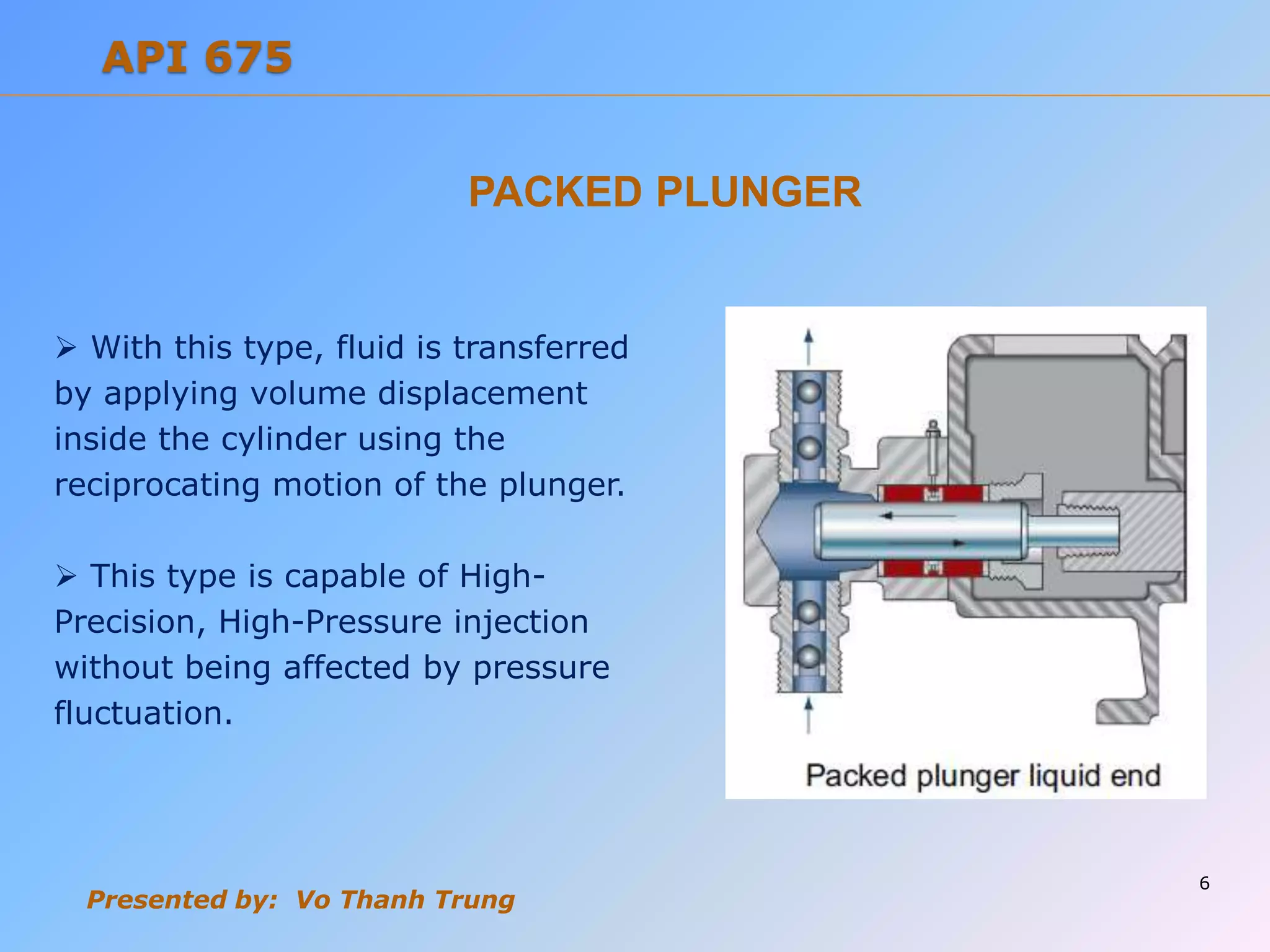
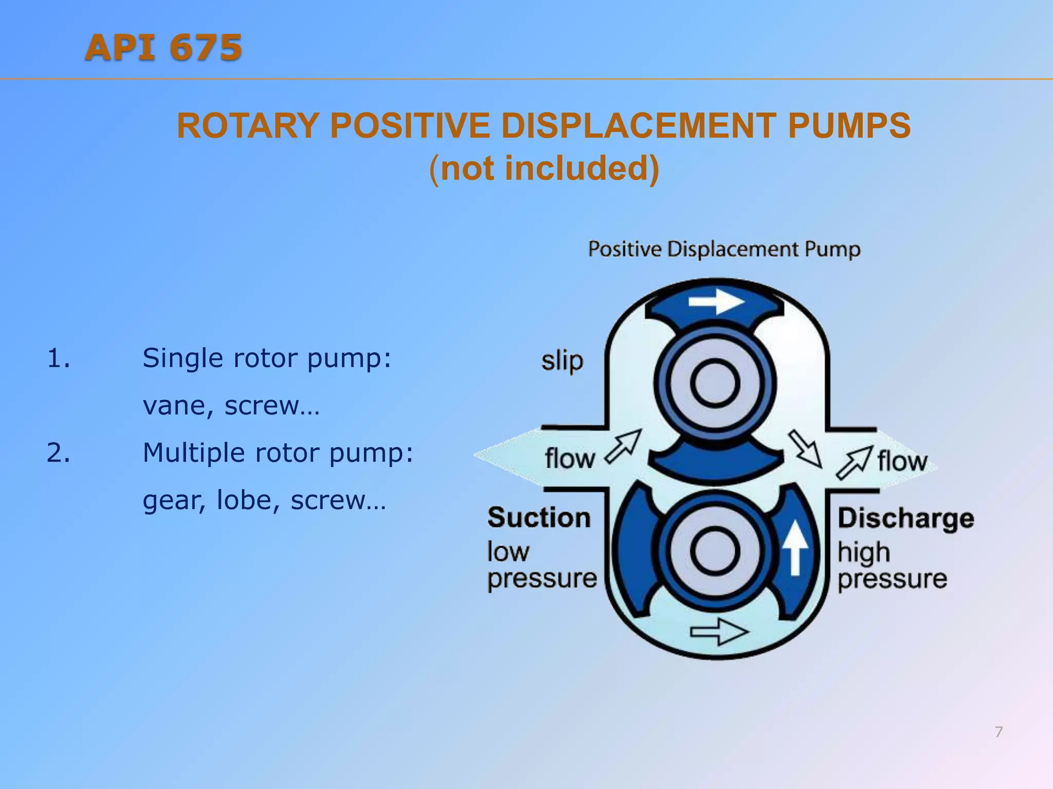
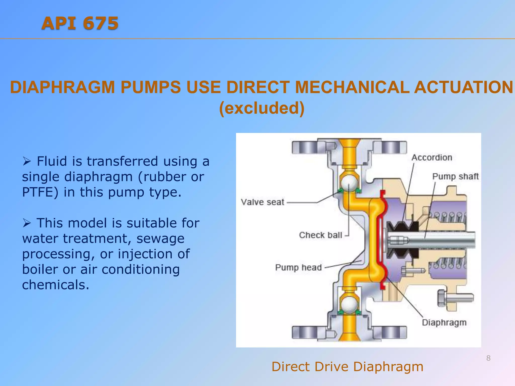
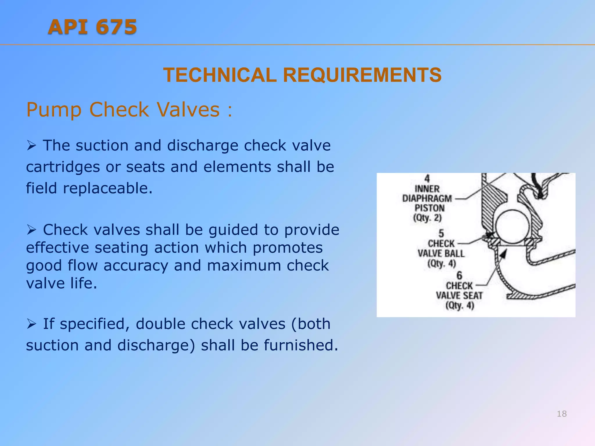
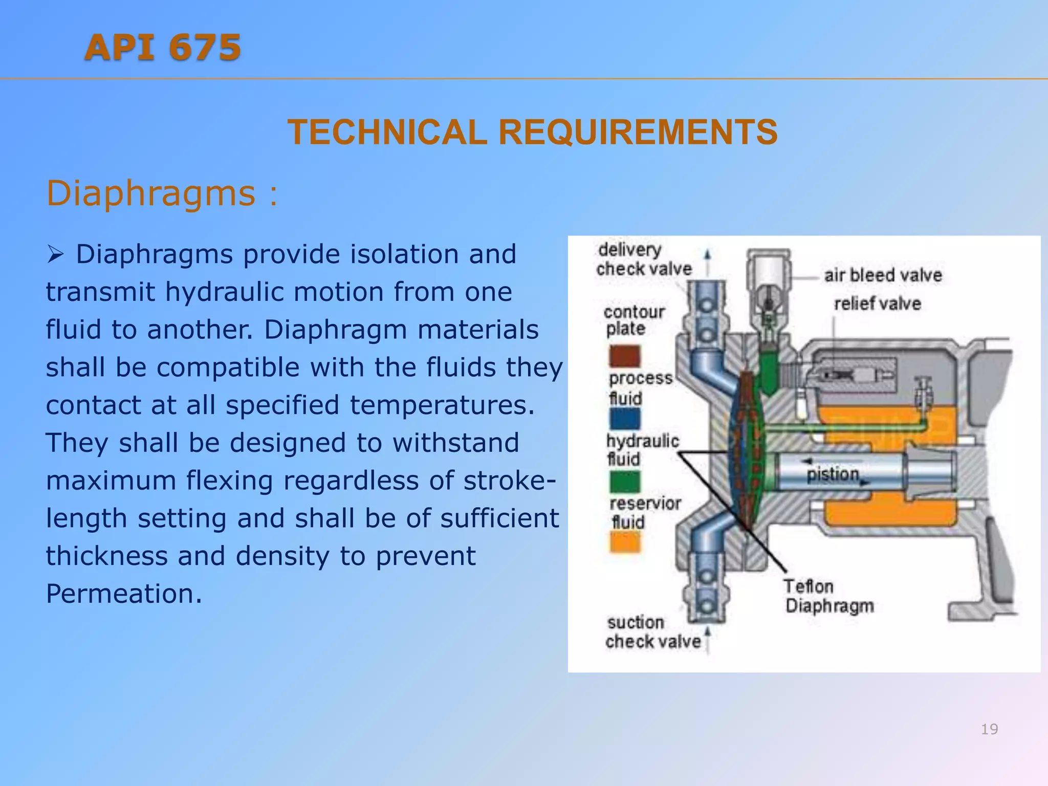
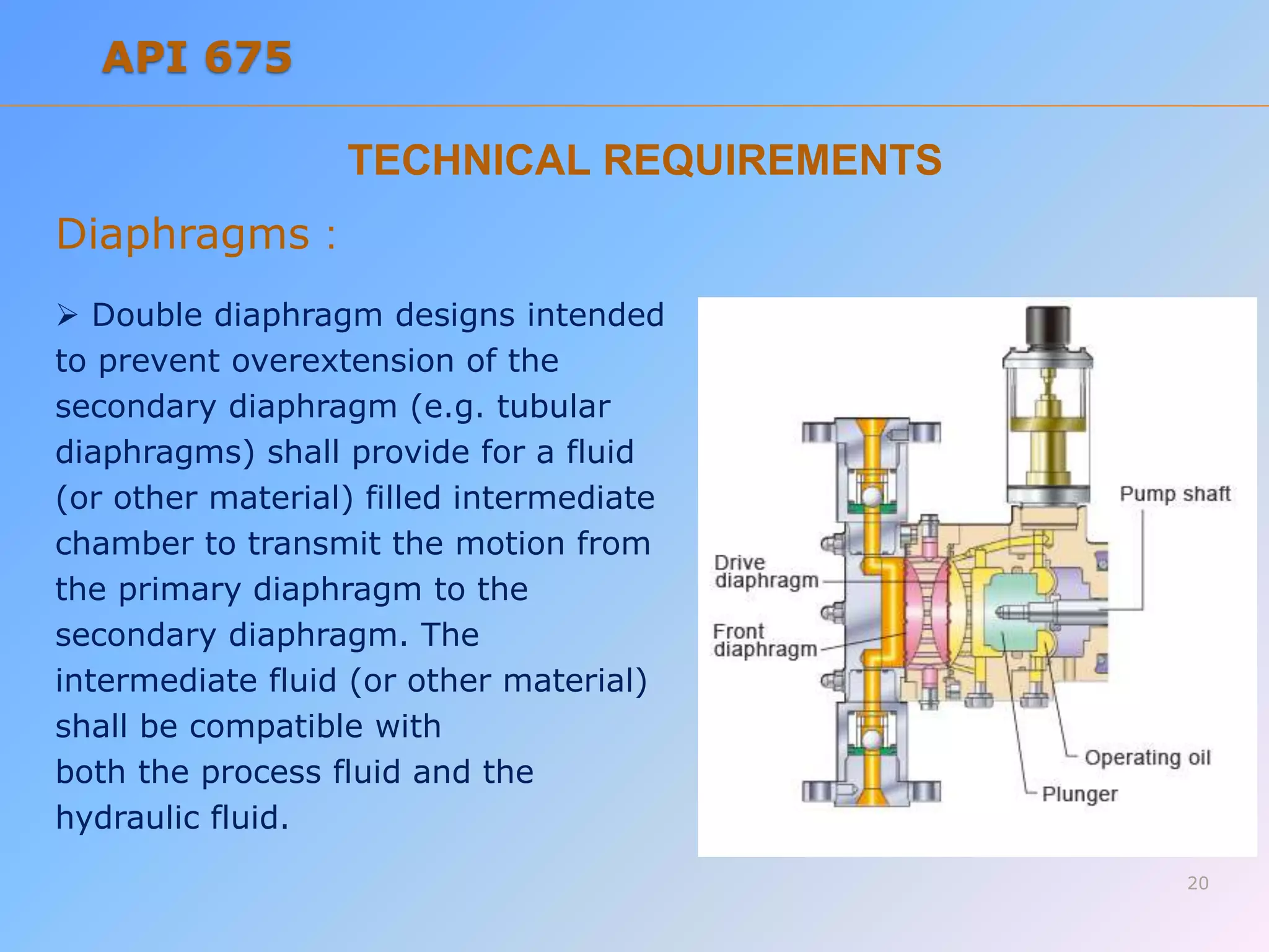
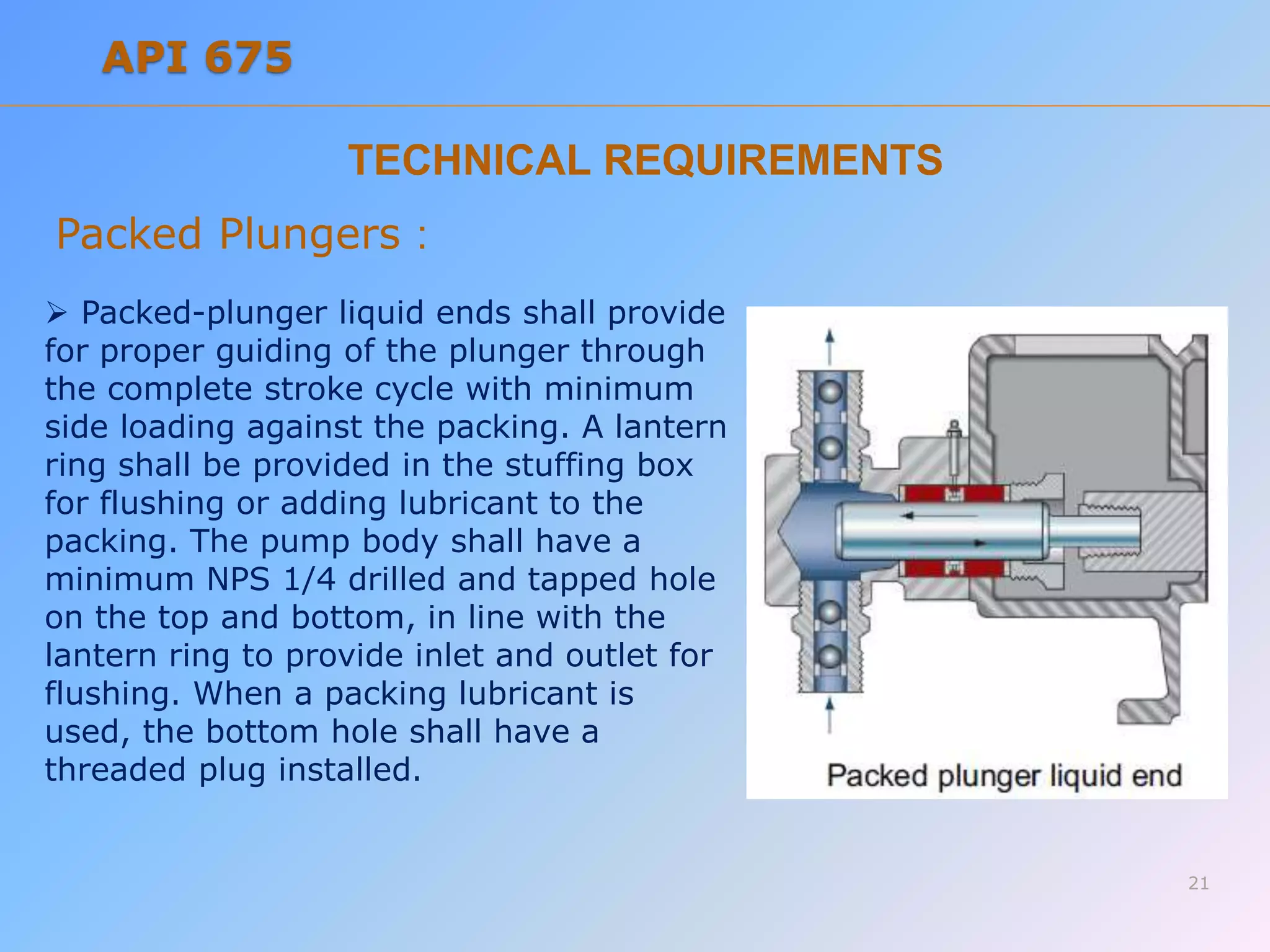
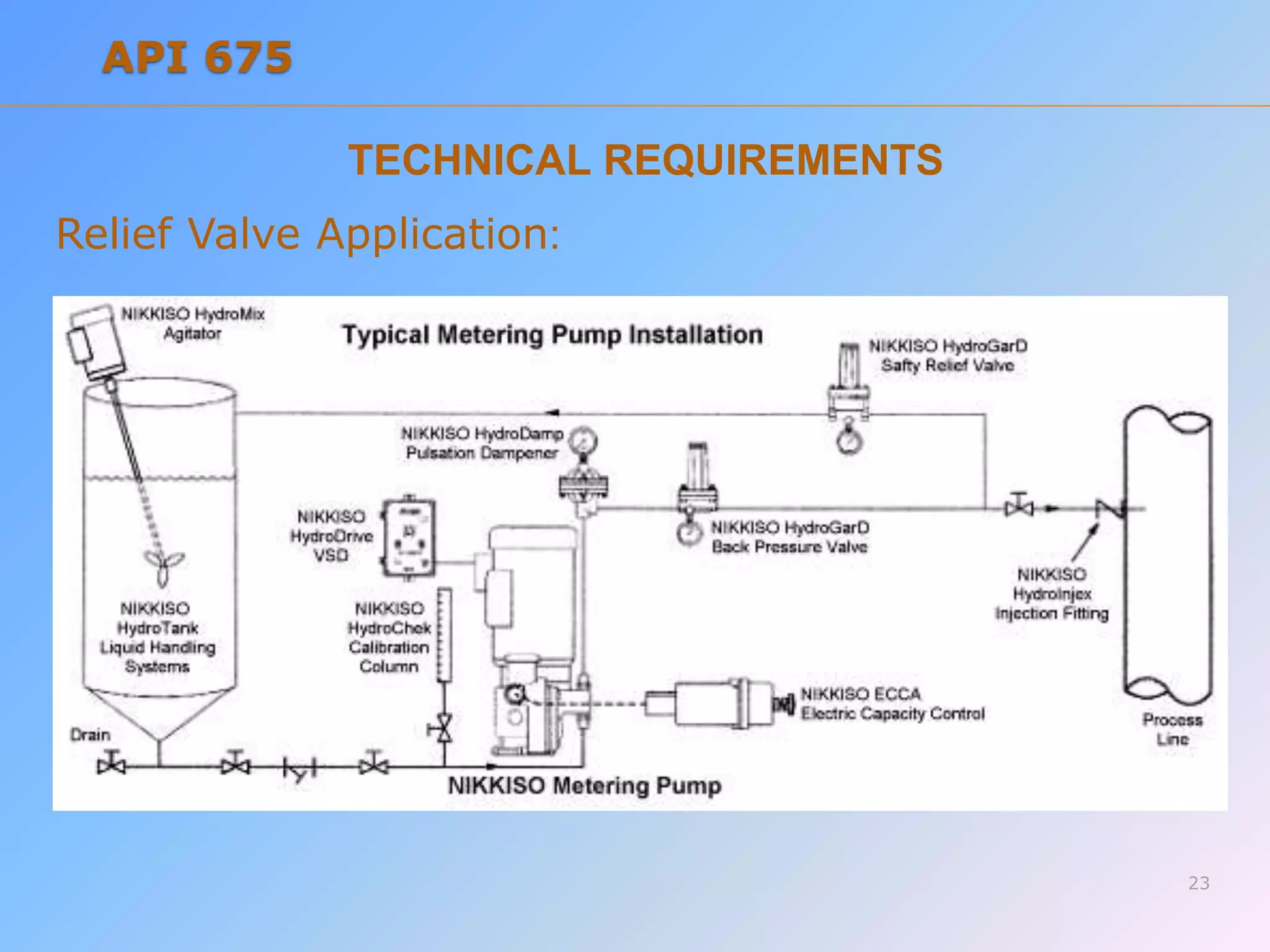
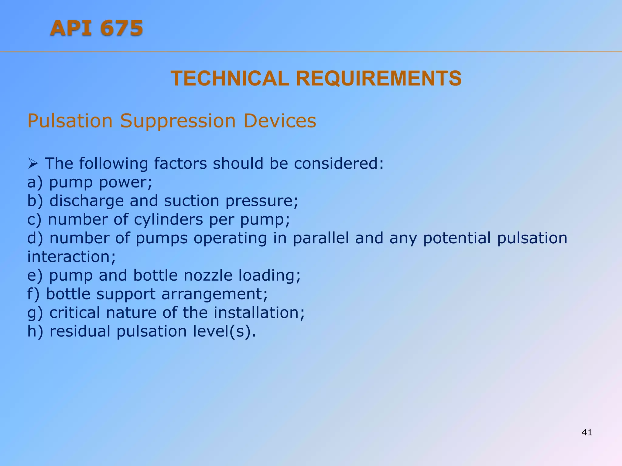
This document outlines technical requirements for positive displacement pumps used in the petroleum, chemical, and gas industries according to API 675 standards. It covers hydraulic diaphragm and packed plunger pump designs, excluding rotary pumps. Requirements include materials of construction, pressure containment, liquid end connections, flanges, check valves, diaphragms, relief valves, gears, bearings, lubrication, capacity control, and accessories like drivers, motors, couplings and guards.
List of API standards for rotating equipmentravisriniv
List of American Petroleum Institute (API) Standards used for rotating equipment in Petroleum, Petrochemical and Oil and Gas Industries like Pumps, Compressors, Turbines and Auxiliary Systems supplied with these rotating equipment and packages.
This Presentation is about working principle of Pumps.Basic Presentation regarding pumps , will definitely help beginners to learn pump types , their working , their parts etc.
Safety is the most important factor in designing a process system. Some undesired conditions might happen leading to damage in a system. Control systems might be installed to prevent such conditions, but a second safety device is also needed. One kind of safety device which is commonly used in the processing industry is the relief valve. A relief valve is a type of valve to control or limit the pressure in a system by allowing the pressurised fluid to flow out from the system.
Within industry, piping is a system of pipes used to convey fluids (liquids and gases) from one location to another. The engineering discipline of piping design studies the efficient transport of fluid
Industrial process piping (and accompanying in-line components) can be manufactured from wood, fiberglass, glass, steel, aluminum, plastic, copper, and concrete. The in-line components, known as fittings, valves, and other devices, typically sense and control the pressure, flow rate and temperature of the transmitted fluid, and usually are included in the field of Piping Design (or Piping Engineering). Piping systems are documented in piping and instrumentation diagrams (P&IDs). If necessary, pipes can be cleaned by the tube cleaning process.
"Piping" sometimes refers to Piping Design, the detailed specification of the physical piping layout within a process plant or commercial building. In earlier days, this was sometimes called Drafting, Technical drawing, Engineering Drawing, and Design but is today commonly performed by Designers who have learned to use automated Computer Aided Drawing / Computer Aided Design (CAD) software
Valve and instrumentation calibration and maintenance will assures the accuracy of your industrial instrumentation and valves in accordance with relevant standards
Rotating equipment maintenance.
PUMPS
COMPRESSORS
AGITATORS
FANS / BLOWERS
TURBINES
VACUUM PUMPS
VALVES
Type of Seals
Stuffing
SINGLE MECHANICAL SEAL Pusher Type
Bellows Mechanical Seal
Double Mechanical Seal
Pressure Safety Valve Sizing - API 520/521/526Vijay Sarathy
No chemical process facility is immune to the risk of overpressure to avoid dictating the necessity for overpressure protection. For every situation that demands safe containment of process gas, it becomes an obligation for engineers to equally provide pressure relieving and flaring provisions wherever necessary. The levels of protection are hierarchical, starting with designing an inherently safe process to avoid overpressure followed by providing alarms for operators to intervene and Emergency Shutdown provisions through ESD and SIL rated instrumentation. Beyond these design and instrument based protection measures, the philosophy of containment and abatement steps such as pressure relieving devices, flares, physical dikes and Emergency Response Services is employed
Ram Pump Brochure - Latham International
`
For more information, Please see websites below:
`
Organic Edible Schoolyards & Gardening with Children =
http://scribd.com/doc/239851214 ~
`
Double Food Production from your School Garden with Organic Tech =
http://scribd.com/doc/239851079 ~
`
Free School Gardening Art Posters =
http://scribd.com/doc/239851159 ~
`
Increase Food Production with Companion Planting in your School Garden =
http://scribd.com/doc/239851159 ~
`
Healthy Foods Dramatically Improves Student Academic Success =
http://scribd.com/doc/239851348 ~
`
City Chickens for your Organic School Garden =
http://scribd.com/doc/239850440 ~
`
Huerto Ecológico, Tecnologías Sostenibles, Agricultura Organica
http://scribd.com/doc/239850233
`
Simple Square Foot Gardening for Schools - Teacher Guide =
http://scribd.com/doc/239851110 ~
MREG-A and MREG-B are angle-way and straightway hand regulating valves, which act as normal stop valves in closed position.
The valves are available in two different versions – MREG-A and MREG-B designed for regulation purposes in liquid and expansion lines.
The valves are designed to meet the strict quality requirements on refrigerating installations specified by the international classification societies and are carefully designed to present favourable flow conditions and accurate linear characteristics.
MREG-A and MREG-B are equipped with vented cap and internal back-seating enables replacement of the spindle seal whilst the valve is active, i.e. under pressure.
PressureJet - World Class Manufacturer and Exporter of High Pressure Hydro Test Pump, Hydro Jetting Machine, Hydro Blasting Machine, High Pressure Cleaning Pump and first choice for Major Industrial Pump Applications.
Pressure Jet offers its customers the best Hydro Jetting Machines available. Hydro jetting pumps, which have undergone extensive testing and are available for sale in both domestic and foreign markets, are produced to order and tailored to the specific needs of the end user. Visit our company's website for any other queries.
Website: https://www.hydrojettingmachine.com/
PressureJet - Manufacturer Of High Pressure Hydro Test Pump, Hydro Jetting Ma...sewerjettingpumps
PressureJet - World Class Manufacturer and Exporter of High Pressure Hydro Test Pump, Hydro Jetting Machine, Hydro Blasting Machine, High Pressure Cleaning Pump and first choice for Major Industrial Pump Applications.
Valves are the components in a fluid flow or pressure system that regulate
either the flow or the pressure of the fluid. This duty may involve stopping
and starting flow, controlling flow rate, diverting flow, preventing back
flow, controlling pressure, or relieving pressure.
Bomba de Palheta Blackmer!
São bombas de deslocamento positivo e com compressores de gás e sem óleo, feitas para aplicações líquidas de CO2 que oferecem um desempenho de alto nível, sendo a eficiência energética, operação sem problemas e baixo custo de manutenção.
SAIBA MAIS
Site: www.vibropac.com.br
Tel: +55 11 2108-5600
E-mail: vibropac@vibropac.com.br
Hybrid optimization of pumped hydro system and solar- Engr. Abdul-Azeez.pdffxintegritypublishin
Advancements in technology unveil a myriad of electrical and electronic breakthroughs geared towards efficiently harnessing limited resources to meet human energy demands. The optimization of hybrid solar PV panels and pumped hydro energy supply systems plays a pivotal role in utilizing natural resources effectively. This initiative not only benefits humanity but also fosters environmental sustainability. The study investigated the design optimization of these hybrid systems, focusing on understanding solar radiation patterns, identifying geographical influences on solar radiation, formulating a mathematical model for system optimization, and determining the optimal configuration of PV panels and pumped hydro storage. Through a comparative analysis approach and eight weeks of data collection, the study addressed key research questions related to solar radiation patterns and optimal system design. The findings highlighted regions with heightened solar radiation levels, showcasing substantial potential for power generation and emphasizing the system's efficiency. Optimizing system design significantly boosted power generation, promoted renewable energy utilization, and enhanced energy storage capacity. The study underscored the benefits of optimizing hybrid solar PV panels and pumped hydro energy supply systems for sustainable energy usage. Optimizing the design of solar PV panels and pumped hydro energy supply systems as examined across diverse climatic conditions in a developing country, not only enhances power generation but also improves the integration of renewable energy sources and boosts energy storage capacities, particularly beneficial for less economically prosperous regions. Additionally, the study provides valuable insights for advancing energy research in economically viable areas. Recommendations included conducting site-specific assessments, utilizing advanced modeling tools, implementing regular maintenance protocols, and enhancing communication among system components.
Hierarchical Digital Twin of a Naval Power SystemKerry Sado
A hierarchical digital twin of a Naval DC power system has been developed and experimentally verified. Similar to other state-of-the-art digital twins, this technology creates a digital replica of the physical system executed in real-time or faster, which can modify hardware controls. However, its advantage stems from distributing computational efforts by utilizing a hierarchical structure composed of lower-level digital twin blocks and a higher-level system digital twin. Each digital twin block is associated with a physical subsystem of the hardware and communicates with a singular system digital twin, which creates a system-level response. By extracting information from each level of the hierarchy, power system controls of the hardware were reconfigured autonomously. This hierarchical digital twin development offers several advantages over other digital twins, particularly in the field of naval power systems. The hierarchical structure allows for greater computational efficiency and scalability while the ability to autonomously reconfigure hardware controls offers increased flexibility and responsiveness. The hierarchical decomposition and models utilized were well aligned with the physical twin, as indicated by the maximum deviations between the developed digital twin hierarchy and the hardware.
About
Indigenized remote control interface card suitable for MAFI system CCR equipment. Compatible for IDM8000 CCR. Backplane mounted serial and TCP/Ethernet communication module for CCR remote access. IDM 8000 CCR remote control on serial and TCP protocol.
• Remote control: Parallel or serial interface.
• Compatible with MAFI CCR system.
• Compatible with IDM8000 CCR.
• Compatible with Backplane mount serial communication.
• Compatible with commercial and Defence aviation CCR system.
• Remote control system for accessing CCR and allied system over serial or TCP.
• Indigenized local Support/presence in India.
• Easy in configuration using DIP switches.
Technical Specifications
Indigenized remote control interface card suitable for MAFI system CCR equipment. Compatible for IDM8000 CCR. Backplane mounted serial and TCP/Ethernet communication module for CCR remote access. IDM 8000 CCR remote control on serial and TCP protocol.
Key Features
Indigenized remote control interface card suitable for MAFI system CCR equipment. Compatible for IDM8000 CCR. Backplane mounted serial and TCP/Ethernet communication module for CCR remote access. IDM 8000 CCR remote control on serial and TCP protocol.
• Remote control: Parallel or serial interface
• Compatible with MAFI CCR system
• Copatiable with IDM8000 CCR
• Compatible with Backplane mount serial communication.
• Compatible with commercial and Defence aviation CCR system.
• Remote control system for accessing CCR and allied system over serial or TCP.
• Indigenized local Support/presence in India.
Application
• Remote control: Parallel or serial interface.
• Compatible with MAFI CCR system.
• Compatible with IDM8000 CCR.
• Compatible with Backplane mount serial communication.
• Compatible with commercial and Defence aviation CCR system.
• Remote control system for accessing CCR and allied system over serial or TCP.
• Indigenized local Support/presence in India.
• Easy in configuration using DIP switches.
Explore the innovative world of trenchless pipe repair with our comprehensive guide, "The Benefits and Techniques of Trenchless Pipe Repair." This document delves into the modern methods of repairing underground pipes without the need for extensive excavation, highlighting the numerous advantages and the latest techniques used in the industry.
Learn about the cost savings, reduced environmental impact, and minimal disruption associated with trenchless technology. Discover detailed explanations of popular techniques such as pipe bursting, cured-in-place pipe (CIPP) lining, and directional drilling. Understand how these methods can be applied to various types of infrastructure, from residential plumbing to large-scale municipal systems.
Ideal for homeowners, contractors, engineers, and anyone interested in modern plumbing solutions, this guide provides valuable insights into why trenchless pipe repair is becoming the preferred choice for pipe rehabilitation. Stay informed about the latest advancements and best practices in the field.
Welcome to WIPAC Monthly the magazine brought to you by the LinkedIn Group Water Industry Process Automation & Control.
In this month's edition, along with this month's industry news to celebrate the 13 years since the group was created we have articles including
A case study of the used of Advanced Process Control at the Wastewater Treatment works at Lleida in Spain
A look back on an article on smart wastewater networks in order to see how the industry has measured up in the interim around the adoption of Digital Transformation in the Water Industry.
Water scarcity is the lack of fresh water resources to meet the standard water demand. There are two type of water scarcity. One is physical. The other is economic water scarcity.
4. This standard covers the minimum requirements for reciprocating,
controlled volume pumps and pump units for use in the petroleum,
petrochemical, and gas industry services.
These pumps are either hydraulic diaphragm or packed plunger design.
Rotary positive displacement pumps are not included. Diaphragm pumps
that use direct mechanical actuation are also excluded.
Presented by: Vo Thanh Trung
SCOPE
4
API 675
5. Presented by: Vo Thanh Trung
HYDRAULIC DIAPHRAGM
This type uses operating oil, such as
silicone, in the cavity between the
diaphragm and the piston and features an
embedded relief (safety) mechanism. This
design is effective for fluids that should not
be in contact with the open air.
This High-Precision Type is capable of
discharging a constant volume despite
pressure fluctuations on the injection side.
It is often used in High-Pressure
applications such as petrochemical
processing because this type is capable of
discharging at a pressure higher than the
Direct Drive Diaphragm Type or the Double
Diaphragm Type.
Hydraulic Diaphragm
Hydraulic Double Diaphragm
5
API 675
6. Presented by: Vo Thanh Trung
PACKED PLUNGER
With this type, fluid is transferred
by applying volume displacement
inside the cylinder using the
reciprocating motion of the plunger.
This type is capable of High-
Precision, High-Pressure injection
without being affected by pressure
fluctuation.
6
API 675
8. DIAPHRAGM PUMPS USE DIRECT MECHANICAL ACTUATION
(excluded)
Fluid is transferred using a
single diaphragm (rubber or
PTFE) in this pump type.
This model is suitable for
water treatment, sewage
processing, or injection of
boiler or air conditioning
chemicals.
8
API 675
Direct Drive Diaphragm
9. PURPOSE
For use in the petroleum, petrochemical, and gas industry
services.
Our positive displacement pumps are designed to handle difficult,
abrasive, corrosive and gaseous fluids.
Continuous dry running and self-priming eliminates the risk of gas
locking or blockage. Precise metering of flow rates from microlitres
per minute to 80 cubic metres per hour, with consistent accuracy
of up to ± 0.5% ensures economical use of expensive chemicals
and optimised system performance.
9
API 675
10. Capacity Adjustment :
Pump capacity shall be adjusted by changing the actual or the effective
stroke length or the pump stroking speed.
The pump shall be capable of accepting manual or automatic capacity
stroke control, either factory mounted or by field conversion.
Integral pump devices used to vary capacity either manually or
automatically shall be provided with visual indication of capacity setting,
shown as a percentage of the maximum stroke length. Manual control
shall include a locking device to positively retain the capacity setting.
CONTROLLED VOLUME
10
API 675
13. TECHNICAL REQUIREMENTS
General:
Motors, electrical components, and electrical installations shall be
suitable for the area classification (class, group, and division or zone)
specified by the Purchaser and shall meet the requirements of the
applicable sections of IEC 60079, or NFPA 70, API 500, and NEC
as specified, as well as any local codes specified and supplied by the
Purchaser.
The pump design shall allow access for adjustment or replacement
of liquid end components including packing, seals, check valves, and
other wetted parts that require maintenance.
The check valves shall be removable from the liquid end for
servicing or replacement.
13
API 675
14. TECHNICAL REQUIREMENTS
General:
The pump flow rate shall be adjustable over the specified turndown
ratio while the pump is running.
Rated capacity shall be at least 110 % of the maximum capacity
specified.
The steady state flow accuracy shall be within ± 1 % of rated flow
over a turndown ratio of at least 10:1.
The flow repeatability shall be within ± 3 % of rated flow over the
specified turndown ratio.
Deviation from linearity shall not exceed ± 3 % of rated flow over
the specified turndown ratio.
14
API 675
15. TECHNICAL REQUIREMENTS
Pressure Containing Parts :
The stress values used in the design of pressure containing parts
shall not exceed the maximum allowable stress values specified in
Section VIII of the ASME Code at the maximum operating
temperature of the material used.
The use of threaded holes in pressure-retaining parts shall be
minimized.
Machined and studded pump connections shall conform to the facing
and drilling requirements of ANSI/ASME B16.1, B16.5, B16.42, or
B16.47 (ISO 7005-1 or 7005-2).
The details of threading shall conform to ASME B1.1 (or ISO 261,
ISO 262, ISO 724, ISO 965).
15
API 675
16. TECHNICAL REQUIREMENTS
Liquid End Connections :
Inlet and outlet connections shall be flanged or machined and
studded, oriented as specified, and shall be suitable for the working
pressure.
Suction and discharge nozzles shall be flanged or machined and
studded for sizes NPS 2 (50 mm) and larger.
Sizes NPS 11/2 (40 mm) and smaller may be threaded connections.
Openings for nozzles and other pressure casing connections shall be
standard pipe sizes in accordance with ISO 6708 or ASME B16.5.
Openings of DN 32, 65, 90, 125, 175, and 225 (NPS 11/4, 21/2, 31/2,
5, 7, and 9) shall not be used.
16
API 675
17. TECHNICAL REQUIREMENTS
Flanges :
Cast iron flanges shall be flat-faced and, except as noted in 6.4.1.3,
conform to the dimensional requirements of ISO 7005-2 and the
flange finish requirements of ASME B16.1 or ASME B16.42.
Flanges other than cast iron shall, as a minimum requirement,
conform to the dimensional requirements of ISO 7005-1 PN 50 except
as noted in 6.4.1.3 and the flange finish requirements of ASME B16.5
or ASME B16.47.
Flanges in all materials that are thicker or have a larger outside
diameter than required by the relevant ASME standards in this
standard are acceptable. Nonstandard (oversized) flanges shall be
identified as such and completely dimensioned on the arrangement
drawing.
17
API 675
18. TECHNICAL REQUIREMENTS
Pump Check Valves :
The suction and discharge check valve
cartridges or seats and elements shall be
field replaceable.
Check valves shall be guided to provide
effective seating action which promotes
good flow accuracy and maximum check
valve life.
If specified, double check valves (both
suction and discharge) shall be furnished.
18
API 675
19. TECHNICAL REQUIREMENTS
Diaphragms :
Diaphragms provide isolation and
transmit hydraulic motion from one
fluid to another. Diaphragm materials
shall be compatible with the fluids they
contact at all specified temperatures.
They shall be designed to withstand
maximum flexing regardless of stroke-
length setting and shall be of sufficient
thickness and density to prevent
Permeation.
19
API 675
20. TECHNICAL REQUIREMENTS
Diaphragms :
Double diaphragm designs intended
to prevent overextension of the
secondary diaphragm (e.g. tubular
diaphragms) shall provide for a fluid
(or other material) filled intermediate
chamber to transmit the motion from
the primary diaphragm to the
secondary diaphragm. The
intermediate fluid (or other material)
shall be compatible with
both the process fluid and the
hydraulic fluid.
20
API 675
21. TECHNICAL REQUIREMENTS
Packed Plungers :
Packed-plunger liquid ends shall provide
for proper guiding of the plunger through
the complete stroke cycle with minimum
side loading against the packing. A lantern
ring shall be provided in the stuffing box
for flushing or adding lubricant to the
packing. The pump body shall have a
minimum NPS 1/4 drilled and tapped hole
on the top and bottom, in line with the
lantern ring to provide inlet and outlet for
flushing. When a packing lubricant is
used, the bottom hole shall have a
threaded plug installed.
21
API 675
22. TECHNICAL REQUIREMENTS
Relief Valve Application:
Diaphragm pumps shall have an integral, adjustable hydraulic relief
valve to provide full protection of the pump drive mechanism from
excessive discharge pressure. The relief valve setting shall be at least
10 % or 175 kPa (25 psi) over the rated discharge pressure,
whichever is greater. The relief valve shall be self-seating and shall be
easily accessible for adjustment, repair, or replacement.
Packed-plunger pumps require external relief valves for mounting in
the Purchaser’s piping
22
API 675
24. TECHNICAL REQUIREMENTS
Gears :
All gears used in the pump drive assembly shall be metal. They shall
be designed with AGMA criteria as a guide and with a minimum
service factor of 1.5 per AGMA 6022 or AGMA 6013 as applicable. The
gear lubrication system shall be self-contained.
24
API 675
25. TECHNICAL REQUIREMENTS
Drive Train Enclosure :
The drive train enclosure shall use materials of sufficient strength
and thickness to provide stable, accurate alignment of drive parts.
The drive train enclosure shall be provided with an oil drain at the
low point of the housing and with fill
provisions so that oil may be changed without disturbing the pump
installation.
All static seals and gaskets on the drive enclosure shall be leakage
free in accordance with 6.1.1. Dynamic
seals shall be easily replaceable.
25
API 675
26. TECHNICAL REQUIREMENTS
Drive Bearings :
Antifriction bearings shall have a minimum L-10 rated life (see ABMA
Standard 9 or ABMA Standard 11) of 25,000 hours with continuous
operation at maximum rated conditions.
Antifriction bearings shall be retained on shafts and fitted into housings
in such a way to guarantee that the required L10 life is met or exceeded.
A proper locking device should be used to prevent loosening of any
bearings.
Single or double-row bearings shall not be of the Conrad type (no filling
slots).
26
API 675
27. TECHNICAL REQUIREMENTS
Lubrication :
The lubrication system shall be of a forced-feed, splash, or submerged
type and shall lubricate the reduction gears, bearings, and all other
required points except the driver.
The Vendor shall state in the operating manual the amount and
specifications for the lubricating and or
hydraulic oil required.
27
API 675
28. TECHNICAL REQUIREMENTS
Capacity Adjustment :
Pump capacity shall be adjusted by changing the actual or the effective
stroke length or the pump stroking speed.
The pump shall be capable of accepting manual or automatic capacity
stroke control, either factory mounted or by field conversion.
Integral pump devices used to vary capacity either manually or
automatically shall be provided with visual indication of capacity setting,
shown as a percentage of the maximum stroke length. Manual control
shall include a locking device to positively retain the capacity setting.
28
API 675
29. TECHNICAL REQUIREMENTS
Materials of Construction :
Unless otherwise specified, the materials of construction of the process
containing components shall be steel as a minimum.
Materials shall be identified by reference to applicable international
standards, including the material grade.
If specified, copper or copper alloys shall not be used for parts that are
in contact with process fluids.
External parts subject to rotary or sliding motions (such as control
linkage joints and adjusting mechanisms) shall be of corrosion-resistant
materials suitable for the site environment.
The Purchaser shall specify any erosive or corrosive agents (including
trace quantities) present in the process fluids and in the site environment,
including constituents that may cause stress-corrosion cracking or attack
elastomers.
29
API 675
30. TECHNICAL REQUIREMENTS
Materials of Construction :
The Purchaser shall specify the amount of wet H2S that may be present,
considering normal operation, start-up, shutdown, idle standby, upsets, or
unusual operating conditions such as catalyst regeneration.
The Vendor should select materials (for Purchaser approval) to avoid
conditions that may result in electrolytic corrosion.
The material specification of all gaskets and O-rings exposed to the
pumped fluid shall be identified in the proposal. O-rings shall be selected
and their application limited in accordance with API 682. O-ring materials
shall be compatible with all specified services. Special consideration shall
be given to the selection of O-rings for highpressure services to ensure
that they will not be damaged upon rapid depressurization (explosive
decompression).
30
API 675
31. TECHNICAL REQUIREMENTS
Low Temperature Service :
The Purchaser shall specify the minimum design metal temperature and
concurrent pressure that the pump will be subjected to in-service. This
temperature shall be used to establish impact test requirements.
To avoid brittle failures, materials and construction for low-temperature
service shall be suitable for the minimum design metal temperature in
accordance with the codes and other requirements specified. The
Purchaser and the Vendor shall agree on any special precautions
necessary with regard to conditions that may occur during operation,
maintenance, transportation, erection, commissioning and testing.
The Purchaser shall specify whether ASME BPVC Section VIII, Division 1,
shall apply with regard to impact-testing requirements.
31
API 675
32. TECHNICAL REQUIREMENTS
Accessories
Drivers
The driver shall be sized to meet all process variations such as changes in the
pressure, temperature, or properties of the fluid handled, and conditions specified
in the inquiry, including plant start-up conditions.
Motors
For motor requirements that are less than 1 HP, the Vendor and Purchaser shall
agree on the motor specification.
Motor drives 1 HP or larger shall conform with IEEE 841. For applications that
utilize an adjustable speed drive, coordination between the pump, motor, and
adjustable speed drive Vendors may be required. The motor rating shall be at least
110 % of the greatest power required (including gear and/or coupling losses) for
any of the specified operating conditions. The motor nameplate rating, including
service factor, shall be suitable for operation at 100 % of the PLV accumulation
pressure. Consideration shall be given to the starting conditions of both the driver
and driven equipment and the possibility that these conditions may be different
from the normal operating conditions. Equipment driven by induction motors shall
be rated at the actual motor speed for the rated load conditions. 32
API 675
33. TECHNICAL REQUIREMENTS
Accessories
Couplings and Guards
Unless otherwise specified, flexible couplings and guards between
drivers and driven equipment shall be supplied by the manufacturer of the
driven equipment.
If specified, couplings shall be balanced to AGMA 9000 Class 10
If specified, couplings shall meet the requirements of API 671.
If specified, electrically insulated couplings shall be provided.
Couplings and coupling to shaft junctures shall be rated for at least the
maximum driver power, including the driver service factor.
Each coupling shall have a guard, which is removable without disturbing
the coupled elements and shall meet the requirements below.
Guards shall enclose the moving elements and the shafts to prevent
personnel from contacting moving parts during operation of the equipment
train. Allowable access dimensions shall comply with specified standards,
such as ISO 14120 or EN 953.
33
API 675
34. TECHNICAL REQUIREMENTS
Accessories
Baseplates
If a baseplate is specified, the Purchaser shall indicate the major
equipment to be mounted on it. A baseplate shall be a single fabricated
steel unit, unless the Purchaser and the Vendor mutually agree that it may
be fabricated in multiple sections.
If a piece of equipment has a mass in excess of 250 kg (550 lb), the
baseplate shall be supplied with horizontal (axial and lateral) jackscrews,
the same size or larger than the vertical jackscrews.
If a baseplate is provided, it shall extend under the drive-train
components so that any leakage from these components is contained
within the baseplate.
34
API 675
35. TECHNICAL REQUIREMENTS
Accessories
Baseplates
The baseplate shall be provided with lifting lugs for at least a four-point
lift. Lifting the baseplate or skid complete with all equipment mounted
shall not permanently distort or otherwise damage the baseplate or the
equipment mounted on it. The Vendor shall advise if a spreader bar is
needed, and if equipment shall be uncoupled before lifting.
If specified, baseplate shall be of the drain-rim or drain-pan type and
shall have a raised lip. Connections for a drain shall be tapped DN 50 (NPS
2) minimum in the raised lip at the pump end and shall be located for
complete drainage. The pan or upper surface of the baseplate shall be
sloped 1:120 minimum toward the drain end.
35
API 675
36. TECHNICAL REQUIREMENTS
Pressure-limiting Valves (PLVs)
PLVs or other protective devices shall be used with all positive
displacement pumps. Rupture disks shall not be used. The sizing, selection
and installation of pressure limiting valves should meet the requirements
of API 520, Part I and API 520, Part II.
Unless otherwise specified, the Purchaser shall provide PLVs in
accordance with API 526. The Vendor shall provide the Purchaser with
information on recommended flow rate and relieving pressure. The Vendor
and Purchaser should review the Purchaser’s valve selection.
If specified, the valve shall be provided by the Vendor.
36
API 675
37. TECHNICAL REQUIREMENTS
Controls and Instrumentation
The controls and instrumentation scope of supply shall be supplied and
installed as per the Purchaser’s specifications and as noted on the
datasheet.
All controls and instrumentation shall be per API 614 and suitable for
the electrical classification and the hazard conditions as identified on the
datasheet.
37
API 675
38. TECHNICAL REQUIREMENTS
Auxiliary Piping
Auxiliary piping, oil piping, instrument piping and process piping shall be
in accordance with the appropriate part of API 614, except as modified in
7.7.2.
Auxiliary piping system materials shall be in accordance with Table 10 of
API 614. If space does not permit the use of DN 12, DN 20, DN 25 (NPS
1/2, NPS 3/4, or NPS 1) pipe, seamless tubing may be supplied. See Table
2.
A thermal relief valve piped to the Purchaser’s vent and drain system
should be considered for auxiliary piping systems that can be blocked in
by a valve closure.
38
API 675
39. TECHNICAL REQUIREMENTS
Special Tools
If special tools or fixtures are required to disassemble, assemble or
maintain the equipment, they shall be included in the quotation and
provided as part of the initial supply of the equipment. For multiple-unit
installations, the requirements for quantities of special tools and fixtures
shall be agreed between Purchaser and Vendor. These, or similar special
tools, shall be used, and their use demonstrated, during shop assembly
and any required post-test disassembly of the equipment.
If special tools are provided, they shall be firmly attached to the pump
or packaged in a separate, rugged metal box or boxes and shall be
marked “special tools for (tag/item number).” Each tool shall be stamped
or tagged to indicate its intended use.
39
API 675
40. TECHNICAL REQUIREMENTS
Pulsation Suppression Devices
If specified, the Vendor shall furnish pulsation suppression devices to be
located at the pump suction and/or discharge connections. The following
are three basic types of pulsation suppression devices.
a) volume bottles without internals;
b) pulsation dampeners using a gas-filled chamber isolated from the
pumped fluid by a piston or elastomeric diaphragm;
c) pulsation filters and attenuators, including proprietary commercial
designs based on acoustical suppression techniques.
40
API 675
41. TECHNICAL REQUIREMENTS
Pulsation Suppression Devices
The following factors should be considered:
a) pump power;
b) discharge and suction pressure;
c) number of cylinders per pump;
d) number of pumps operating in parallel and any potential pulsation
interaction;
e) pump and bottle nozzle loading;
f) bottle support arrangement;
g) critical nature of the installation;
h) residual pulsation level(s).
41
API 675