The document summarizes the key steps and activities involved in an optical fiber communication training seminar pursued at Aksh Optifibre Ltd. in 2016-2017. It discusses the company profile, provides an introduction to the training, and outlines the main topics covered including the basics of optical fiber communication, fiber installation processes like trenching and blowing fiber, splicing techniques, and using equipment like OTDR for fault detection and loss measurement. The training aimed to teach technicians about optical fiber technologies and prepare them to install and maintain fiber networks.


![ The International turnkey projects:
Bhutan : Aksh Optifibre Limited has been successfully completed the assignment
installing of 2600 Km of All Dielectric Self Supporting (ADSS) optical fibre cable
under Bhutan Power Corporation Limited.
Mauritius : In Mauritius, Aksh has received contract from BTL Mauritius to supply and
install FTTH triple play equipment.
In 2002, AKSH started its 1st Fibre to the Home (FTTH) in Jaipur and later collaborated with
MTNL & BSNL in Jan 2010 to launch FTTH triple play service in Rajasthan.
I have done my training from Aksh Optifibre Ltd. Jaipur, Service Division, Sitapura ,Jaipur.
Aksh Optifibre Limited reports strong financial results for Q4 FY16 & FY 2015-16. Revenue
increased by 23% to Rs. 462 crores, New Delhi, May 30, 2016
Fig. 1: Aksh Products & Services [ 1 ]](https://image.slidesharecdn.com/akshtraining-170103134936/85/Optical-fiber-Communication-training-ppt-4-320.jpg)
![• Basics of OFC :-
An optical fibre is a thin, flexible, transparent fiber that acts as a waveguide, or "light
pipe", to transmit light between the two ends of the fiber. Optical fibers are widely
used in fiber-optic communications, which permits transmission over longer
distances and at higher bandwidths (data rates) than other forms of communication.
Fibers are used instead of metal wires because signals travel along them with less
loss and are also immune to electromagnetic interference.
Fig. 2: Cross Section of Optical Fiber & Schematic of OFC [ 2 ]](https://image.slidesharecdn.com/akshtraining-170103134936/85/Optical-fiber-Communication-training-ppt-7-320.jpg)
![• How Fiber Works :-
The operation of an optical fiber is based on the principle of total internal
reflection. Light reflects (bounces back) or refracts (alters its direction while
penetrating a different medium), depending on the angle at which it strikes a
surface.
The angle of refraction at the interface between two media is governed by
Snell’s law:
n1 sin1 n2 sin2
Fig. 3 :Total Internal Reflection [2]](https://image.slidesharecdn.com/akshtraining-170103134936/85/Optical-fiber-Communication-training-ppt-8-320.jpg)
![• The Design of Fiber :-
The composition of the cladding glass relative to the core glass determines the fibre's
ability to reflect light.
That reflection is usually caused by creating a higher refractive index in the core of the
glass than in the surrounding cladding glass.
The refractive index of the core is increased by slightly modifying the composition of
the core glass, generally by adding small amounts of a dopant.
Fig. 4 :TIR In Optical Fibre [2]](https://image.slidesharecdn.com/akshtraining-170103134936/85/Optical-fiber-Communication-training-ppt-9-320.jpg)
![• Construction of Optical Fibre :-
There are two main types of fiber optic cables :-
-> Single Mode Fiber (SMF)
-> Multi-Mode Fiber (MMF)
Multi-Mode Fiber
-> The wide core allows multiple modes of light
to propagate.
-> MMF has a much wider core (typically 62.5µm
or 50µm), allowing multiple modes (or “rays”)
of light to propagate.
-> Uses aqua coloured cables, rather than the
traditional orange.
-> Designed to achieve 10Gbps up to 300 meters.
Single-Mode Fiber
-> SMF has a very narrow core (typically around
9µm), which allows only single mode of light
to propagate.
-> Can support distances of up to several
thousand kilometres, with appropriate
amplification and dispersion compensation.
Fig. 5: SMF & MMF [3]](https://image.slidesharecdn.com/akshtraining-170103134936/85/Optical-fiber-Communication-training-ppt-10-320.jpg)
![• Colour Coding :-
The type of fiber can be
identified by use the of
standardized colours on
the outer jacket. As shown
in the given figure 6(a).
Now to define the position
of further fibre hair, there
is an another colour code
for the positioning of fiber.
As shown in the figure
6(b).
Fig. 6
(a. Colour
code for outer
jacket)
(b. Colour
code for fiber
hair) [4]](https://image.slidesharecdn.com/akshtraining-170103134936/85/Optical-fiber-Communication-training-ppt-11-320.jpg)
![• Optical Networks :-
Passive Optical Network (PON)
-> Fiber-to-the-home (FTTH) :- Each subscriber is connected by a dedicated fibre to a port
on the equipment in the PON, or to the passive optical splitter, using shared feeder fibre to
the PON.
-> Fiber to the Distribution Point (FTTDp) :- This solution has been proposed in the last
two years. Connecting the POP to the Distribution Point via the optical cable and then from
the Distribution Point to the end-user premises via existing copper infrastructure.
Fig. 7:
Different types
of FTTx
networks.
[4]](https://image.slidesharecdn.com/akshtraining-170103134936/85/Optical-fiber-Communication-training-ppt-12-320.jpg)
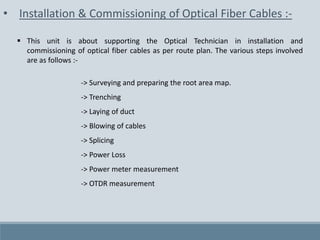
![• Surveying & preparing area root map :-
It is the first and most significant step of optical fiber installation.
Here, first a survey team is sent to the targeted area, where they do a survey on
number of customers interested and how the fibre will be laded.
The task of the optical engineer is to draw an root map according to the
requirement, in such way that minimum of resources used.
Then the engineer makes a rough sketch of fibre laying root, and then sent it to
service division for other formalities.
Fig. 8 :(a) Desktop Survey using Google
Street View [4]
Fig. 8 :(b) High-level planning – colour-coded
distribution locations and areas [4]](https://image.slidesharecdn.com/akshtraining-170103134936/85/Optical-fiber-Communication-training-ppt-14-320.jpg)
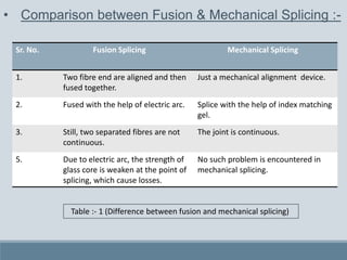
![• Trenching & Laying of duct :-
A trench is a type of excavation or depression in the ground that is generally deeper
than it is wide (as opposed to a wider gully, or ditch), and narrow compared to its
length.
The advantages of this technique over conventional cable laying technologies lie
essentially in its speed of execution, lower cost, significantly lower environmental
impact and limited disruption to road traffic and, as a consequence of the previous
items, easiness in obtaining permits for the taking over of public area.
Trenching is carried out by labour workers as per the route plan requirements and
site terrain.
Fig. 9 : Trenching Process [5]](https://image.slidesharecdn.com/akshtraining-170103134936/85/Optical-fiber-Communication-training-ppt-15-320.jpg)
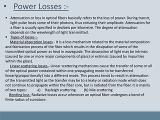
![ After trenching, the next step is laying of duct in trench.
Duct is that pipe in which fibre cables are going to blown.
They are made up of hard plastic.
The another method of laying duct is through HDD.
HDD :- HDD stands for Horizontal Directional Drilling , it is used to lay duct without
trenching the ground. It has a flexible drilling bid which drills under ground up to 1-3 Km.
Fig. 10: HDD Machine [5]](https://image.slidesharecdn.com/akshtraining-170103134936/85/Optical-fiber-Communication-training-ppt-16-320.jpg)
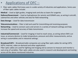
![• Cable Jetting :-
Fig. 11: Blowing of Optical fibre in duct [5]
Traditionally fibre optic cables were pulled through cable ducts in the same way as
other cables, via a winch line.
The technique of installing flexible and lightweight fibre optic units using compressed
air was developed during the 1980s by British Telecom. This early version of jetting did
not use additional pushing. True cable jetting was invented by Willem Griffioen of KPN
Research in the late 1980s.
Cable jetting is the process of blowing a cable through a duct while simultaneously
pushing the cable into the duct.
Compressed air is injected at the duct inlet and flows through the duct and along the
cable at high speed.](https://image.slidesharecdn.com/akshtraining-170103134936/85/Optical-fiber-Communication-training-ppt-17-320.jpg)
![• Splicing of Optical Fiber :-
Fiber optic splicing involves joining two fiber optic cables together. The other, more
common, method of joining fibers is called termination or connectorization.
Fiber splicing typically results in lower light loss and back reflection than termination
making it the preferred method when the cable runs are too long for a single length of
fiber or when joining two different types of cable together, such as a 48-fiber cable to
four 12-fiber cables.
Splicing is also used to restore fiber optic cables when a buried cable is accidentally
severed.
There are two methods of fiber optic splicing,
-> Fusion splicing
-> Mechanical splicing
Fig. 12: A technician doing fusion
splicing [6]](https://image.slidesharecdn.com/akshtraining-170103134936/85/Optical-fiber-Communication-training-ppt-18-320.jpg)
![1. Fusion Splicing :-
Fusion splicing is the process of fusing or welding two fibers together usually by an
electric arc.
Fusion splicing is the most widely used method of splicing as it provides for the lowest
loss and least reflectance, as well as providing the strongest and most reliable joint
between two fibers.
Fusion splicing may be done one fiber at a time or a complete fiber ribbon from ribbon
cable at one time. First we'll look at single fiber splicing and then ribbon splicing.
Fusion splicing machines are mostly automated tools that require you pre-set the splicing
parameters or choose factory recommended settings that will control the splicing process
itself.
Fig. 13: Fusion
Arc Principle &
Fusion Splicing
Tool [7]](https://image.slidesharecdn.com/akshtraining-170103134936/85/Optical-fiber-Communication-training-ppt-19-320.jpg)
![-> Steps involved in fusion splicing :-
First of all the jacket and cladding of two fibre ends which are to be joined, are
removed with the help of a special tool, ‘Stripper’.
After stripping the cladding, the glass core is cleaned with ethyl alcohol.
Now, for an efficient splicing, it is require that the both ends are at 90 deg. finish.
For this, a special precision diamond cutter is used, which is known as ‘Cleaver’.
A precision fiber cleaver that scribes and breaks (cleaves) the fibers to be spliced
precisely, as the quality of the splice will depend on the quality of the cleave. Most
splicing machines come with a recommended cleaver.
Fig. 14: Cleaver & Various types of Strippers [7]](https://image.slidesharecdn.com/akshtraining-170103134936/85/Optical-fiber-Communication-training-ppt-20-320.jpg)
![-> Fuse the fiber - There are two steps within this step, alignment and heating.
Automatic Fiber Alignment
The ends of the fibers are on moveable stages which are used to align the fibers and set the
end gap automatically.
Heating
Now, an electric arc is produce within the splicer and then two fibres are fused together.
Splicing machines also generally have a heating device for heat shrinking a protective sleeve
over the finished splice to protect it from moisture or other environmental hazards.
Fig. 15: Automatic fiber alignment & wrapping of protective sleeve [7]](https://image.slidesharecdn.com/akshtraining-170103134936/85/Optical-fiber-Communication-training-ppt-21-320.jpg)
![2. Mechanical Splicing :-
In mechanical splicing the fibers are precisely aligned and held in place by a self-contained
assembly, not a permanent bond. This method aligns the two fiber ends to a common centre
line, aligning their cores so the light can pass from one fiber to another.
Four steps to performing a mechanical splice:
Step 1: Preparing the fiber - Strip the protective coatings, jackets, tubes, strength members, etc.
leaving only the bare fiber showing. The main concern here is cleanliness.
Step 2: Cleave the fiber - The process is identical to the cleaving for fusion splicing but the cleave
precision is not as critical.
Step 3: Mechanically join the fibers - There is no heat used in this method. Simply position the
fiber ends together inside the mechanical splice unit. The index matching gel inside the
mechanical splice apparatus will help couple the light from one fiber end to the other. Older
apparatus will have an epoxy rather than the index matching gel holding the cores together.
Step 4: Protect the fiber - the completed mechanical splice provides its own protection for the
splice.
Fig. 16: Mechanical
Splicing [7]](https://image.slidesharecdn.com/akshtraining-170103134936/85/Optical-fiber-Communication-training-ppt-22-320.jpg)
![• Power Meter :-
The most basic fiber optic measurement is optical power from the end of a fiber. This
measurement is the basis for loss measurements as well as the power from a source or
presented at a receiver.
Measurement of the power of a transmitter is done by attaching a test cable to the
source and measuring the power at the other end. For receivers, one disconnects the
cable attached to the receiver receptacle and measures the output with the meter.
Optical power meters typically use semiconductor detectors since they are sensitive to
light in the wavelengths and power levels common to fiber optics. Most fiber optic
power meters are available with a choice of 3 different detectors, silicon (Si),
Germanium (Ge), or Indium-Gallium-Arsenide (In GaAs).
Fig. 17: Power Meter Principle & Measurement [8]](https://image.slidesharecdn.com/akshtraining-170103134936/85/Optical-fiber-Communication-training-ppt-25-320.jpg)
![• OTDR Measurement :-
The OTDR is the most important investigation tool for optical fibres, which is applicable for
the measurement of fibre loss, connector loss and for the determination of the exact place
and the value of cable discontinuities.
Fig. 18: The structure of the OTDR instrument [8]](https://image.slidesharecdn.com/akshtraining-170103134936/85/Optical-fiber-Communication-training-ppt-26-320.jpg)
![ The principal of the OTDR analyser is the following: a short light pulse is transmitted into the
fibre under test and the time of the incidence and the amplitude of the reflected pulses are
measured.
The resolution of the OTDR – the dead zone
The resolution of the OTDR system is the distance of two reflecting points that still can be
distinguished by the instrument. This depends on the width of the transmitted impulse, since
the impulse must not overlap.
Fig. 19: The information in the OTDR trace & A typical OTDR [9]](https://image.slidesharecdn.com/akshtraining-170103134936/85/Optical-fiber-Communication-training-ppt-27-320.jpg)
![Advantages of Optical Fiber :-
Fig. 20: Comparison between wireless, ADSL & fibre [10]](https://image.slidesharecdn.com/akshtraining-170103134936/85/Optical-fiber-Communication-training-ppt-29-320.jpg)