This document provides an overview of On-Board Diagnostics (OBD) II systems and how to use an automotive scan tool. It describes key OBD II concepts like Diagnostic Trouble Codes, readiness monitors, and the various OBD II modes of operation. The document also provides instructions on navigating the scan tool user interface and performing functions like reading and erasing codes and viewing live data. Safety precautions are outlined at the beginning for using scan tools when working on vehicles.
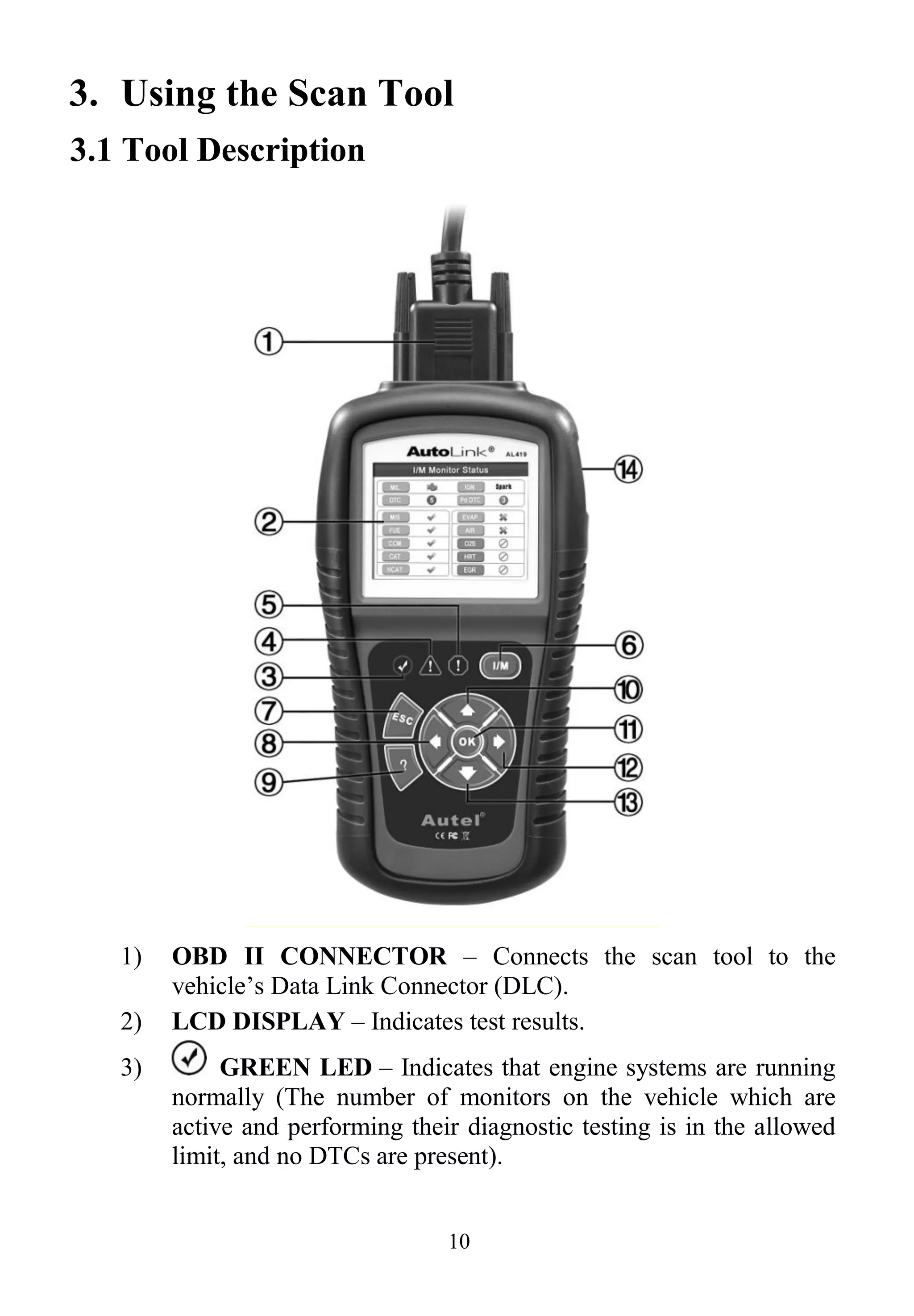
![14
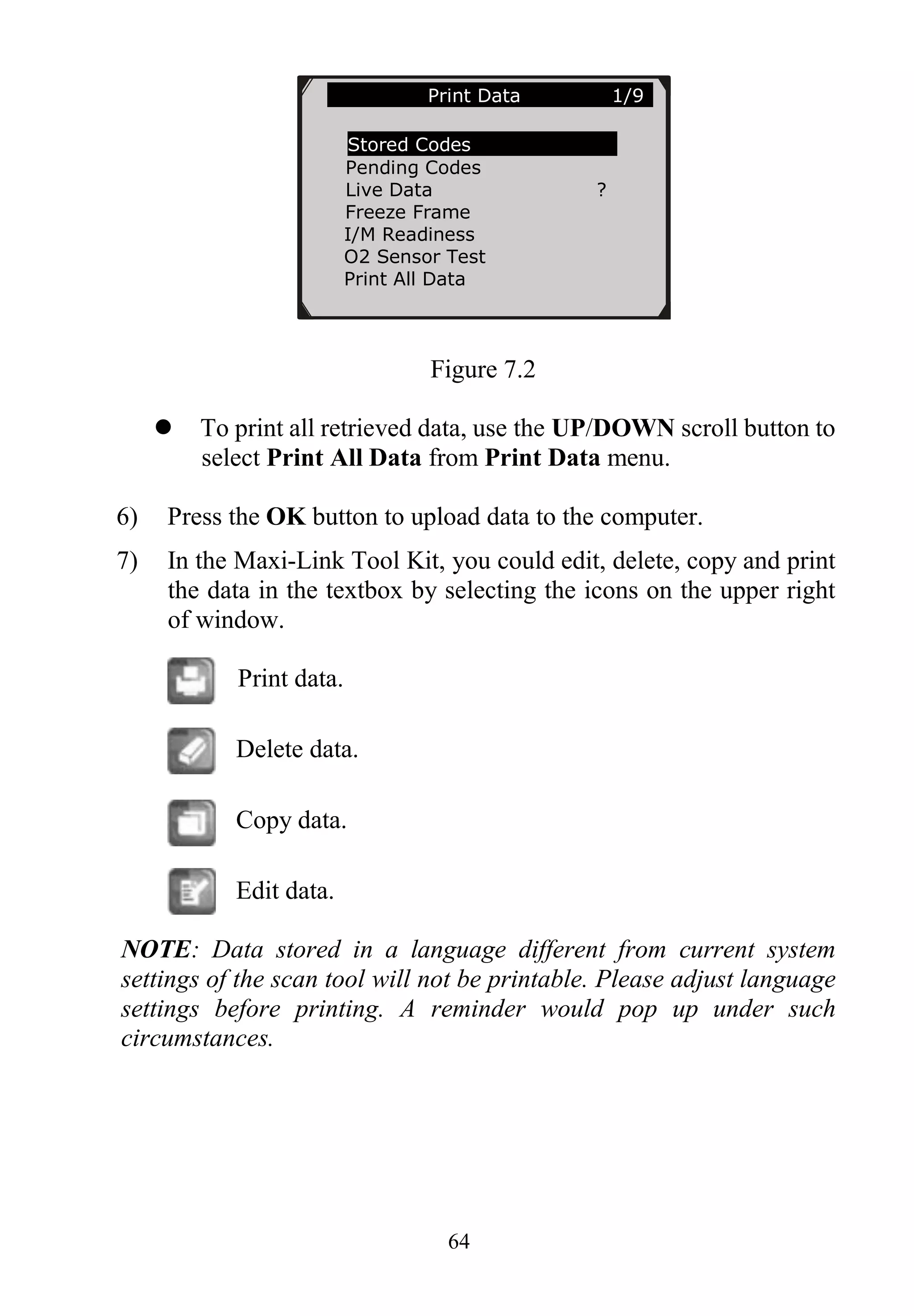
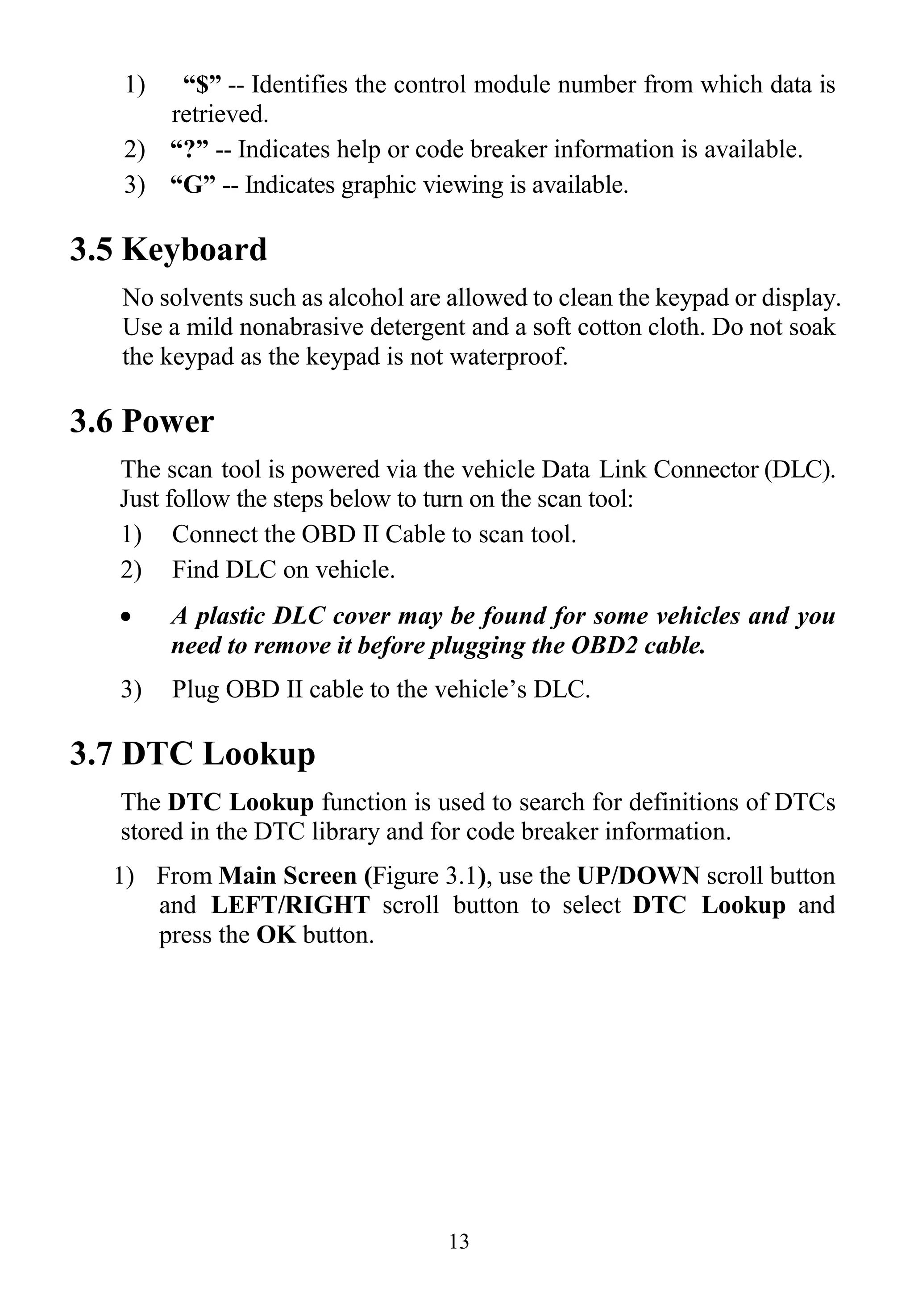
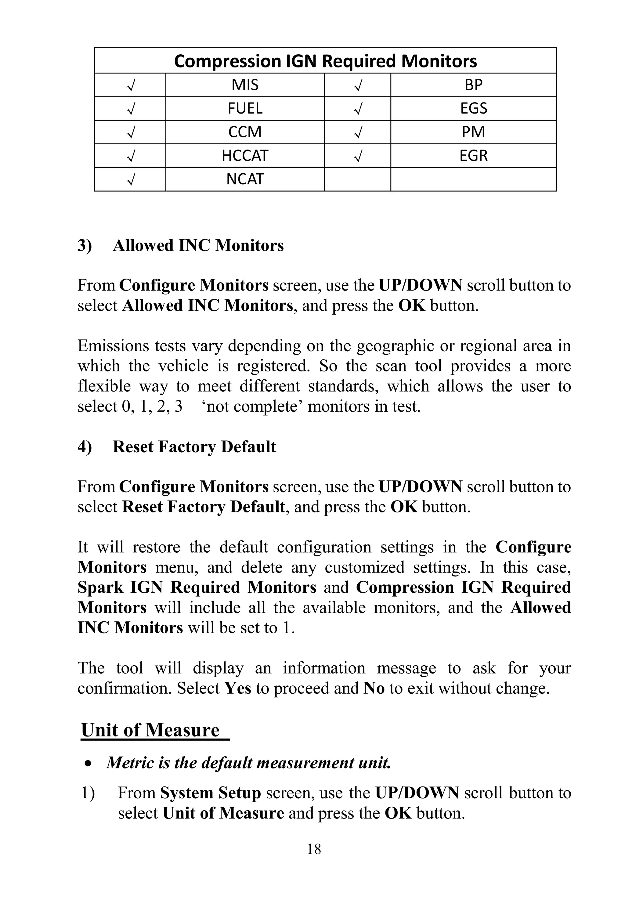
Figure 3.1
2) From DTC Lookup screen, use the LEFT/RIGHT button to
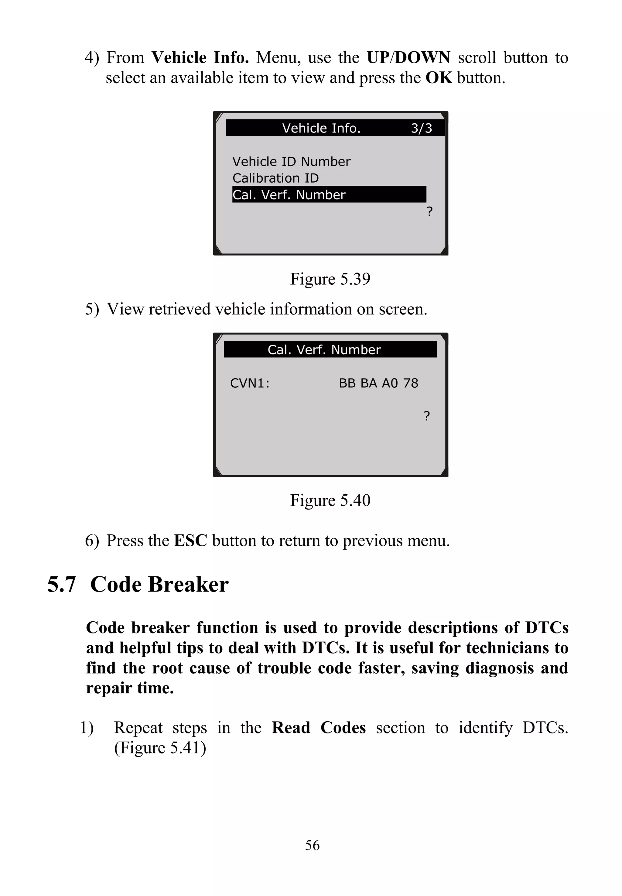
move to the desired character, use the UP/DOWN button to
change selected digit/character and press the OK button to
confirm. (Figure 3.2)
Figure 3.2
3) View the DTC definition on screen. When DTC definition covers
more than one screen, use the LEFT/RIGHT button or
UP/DOWN button to view additional information on
previous/next screens.
For manufacturer specific codes, you need to select a vehicle
make on an additional screen to look for DTC definitions.
If definition could not be found (SAE or Manufacturer
Specific), the scan tool displays “Please refer to vehicle
service manual!”
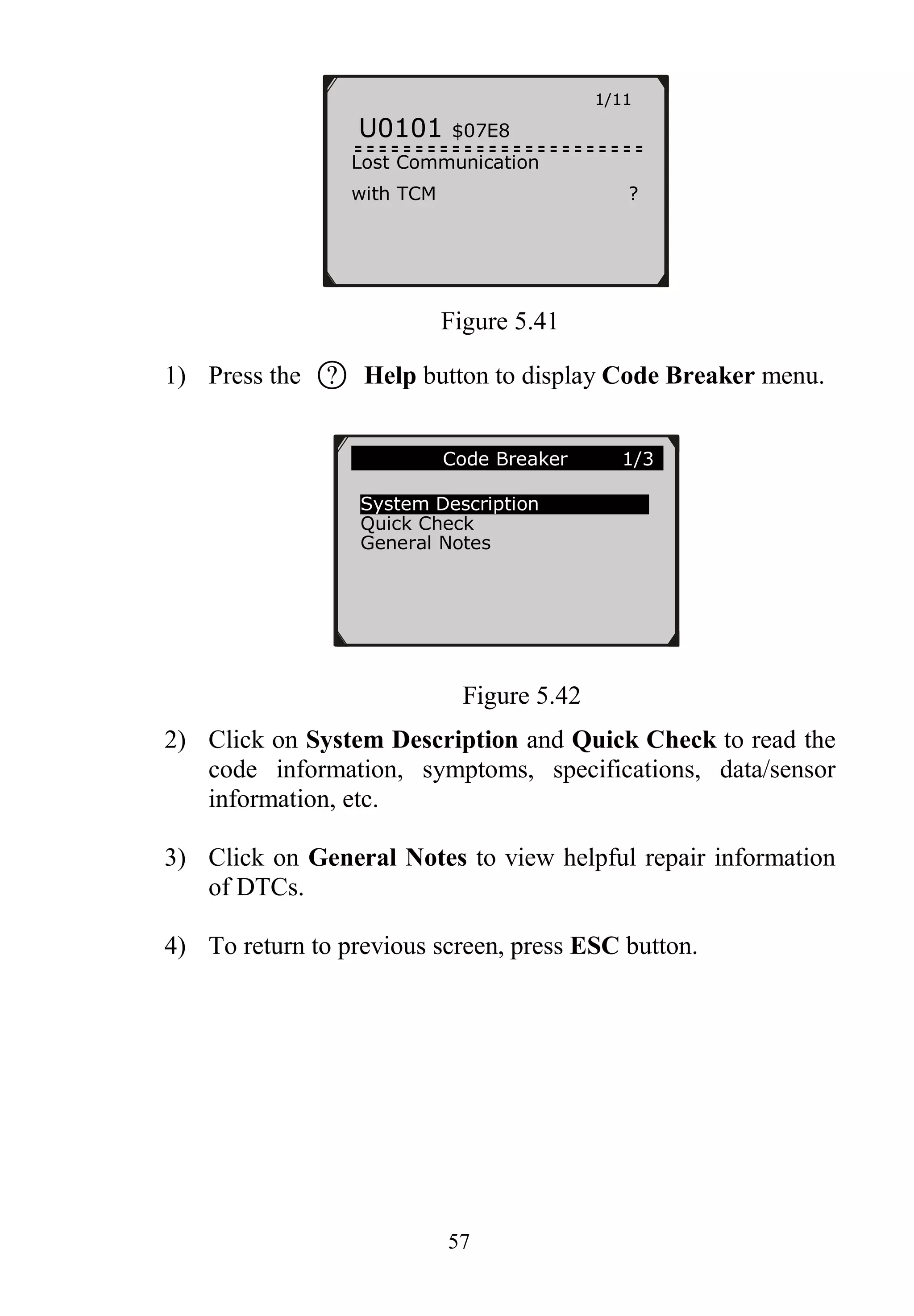
For code breaker information, you need to press the “?” Help
button.
DTC Lookup
P 0 0 0 1
Left
Right
Change digit
OK Confirm
ESC Exit
[ ][ ]- Change Digit
[ENTER]- Confirm
[ESC]- Exit](https://image.slidesharecdn.com/autel-autolink-al419-user-manual-140823232733-phpapp01/75/Autel-Autolink-Al419-User-Manual-15-2048.jpg)
![22
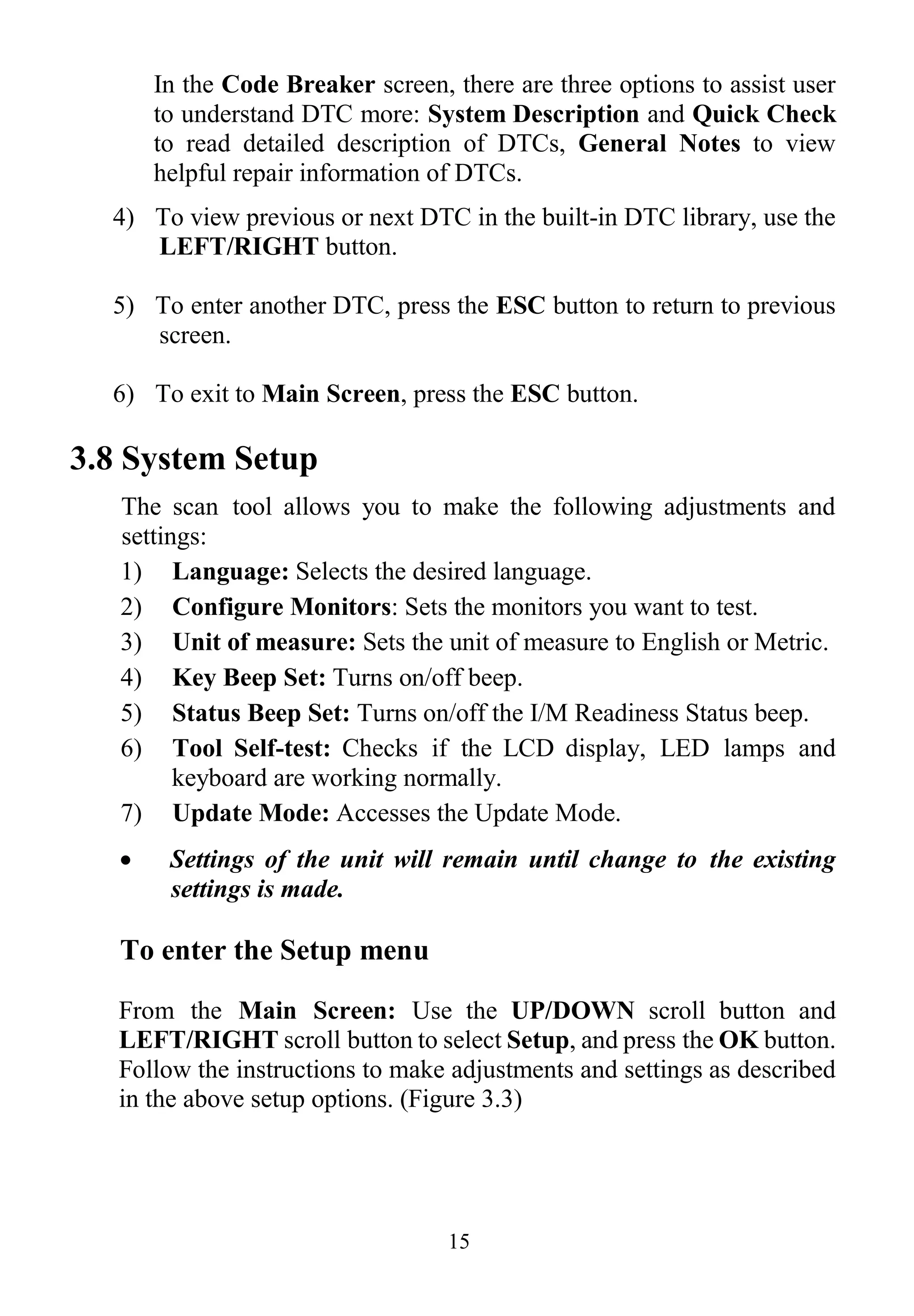
Figure 3.10
3) Double press ESC to return to previous menu.
C. LED Test
The LED Test function verifies if the I/M Readiness LED indicator
lamps are functioning properly.
1) Use the UP/DOWN scroll button to select LED Test from the
Tool Self-test menu, and then press the OK button.
2) In the LED Test menu, use the UP/DOWN scroll button to
select one or more LED lamps to check. The LED should turn
on or off according to the selected commands.
Figure 3.11
3) When completed, press the ESC button to exit.
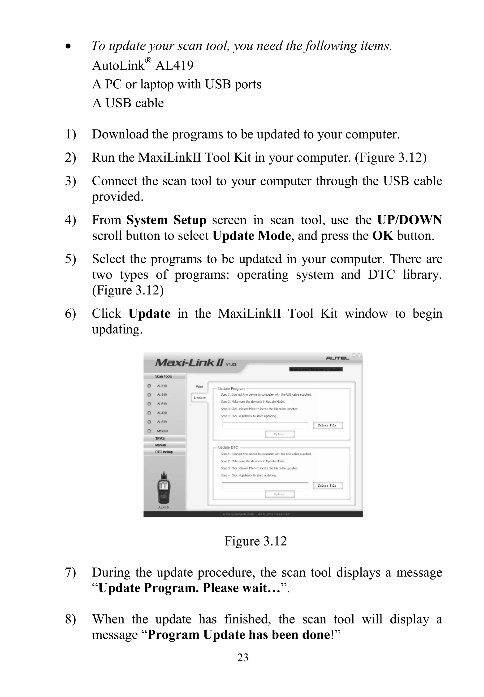
Update Mode
This function allows you to update the scan tool software and DTC
library through a computer.
Keyboard Test
Press any key to
start test
key:
Double [ESC] to return
LED Test 1/3
RED LED ON
YELLOW LED ON
GREEN LED ON](https://image.slidesharecdn.com/autel-autolink-al419-user-manual-140823232733-phpapp01/75/Autel-Autolink-Al419-User-Manual-23-2048.jpg)
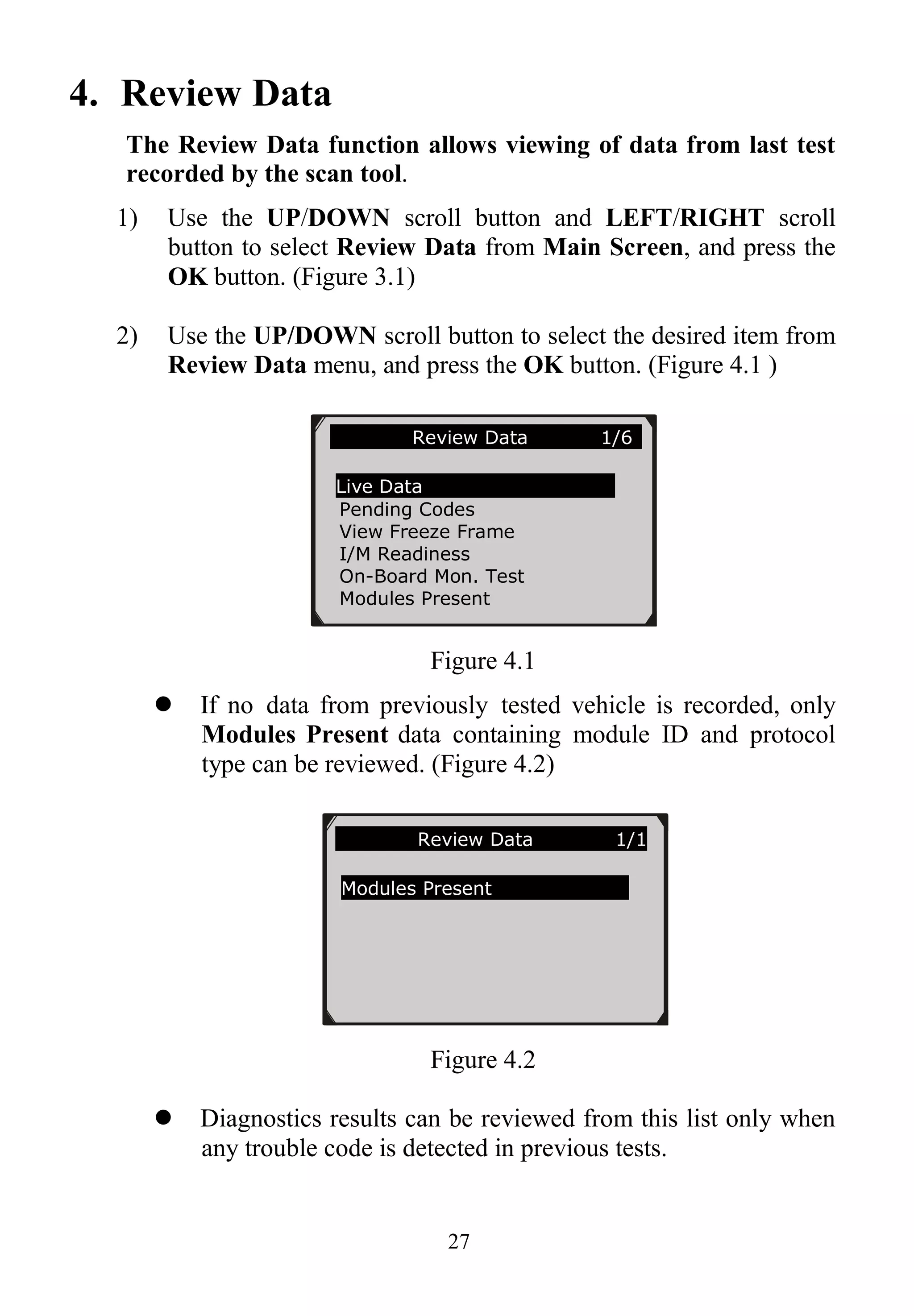
![29
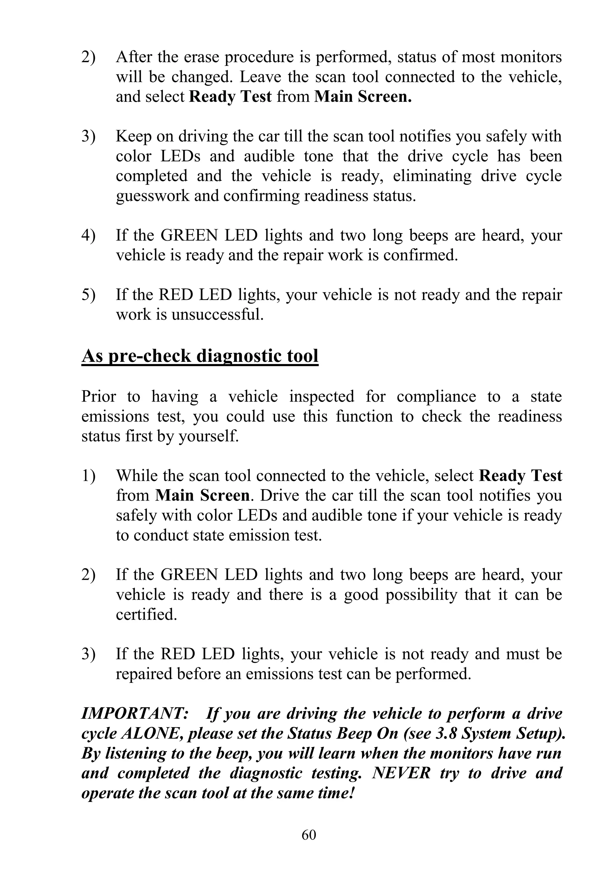
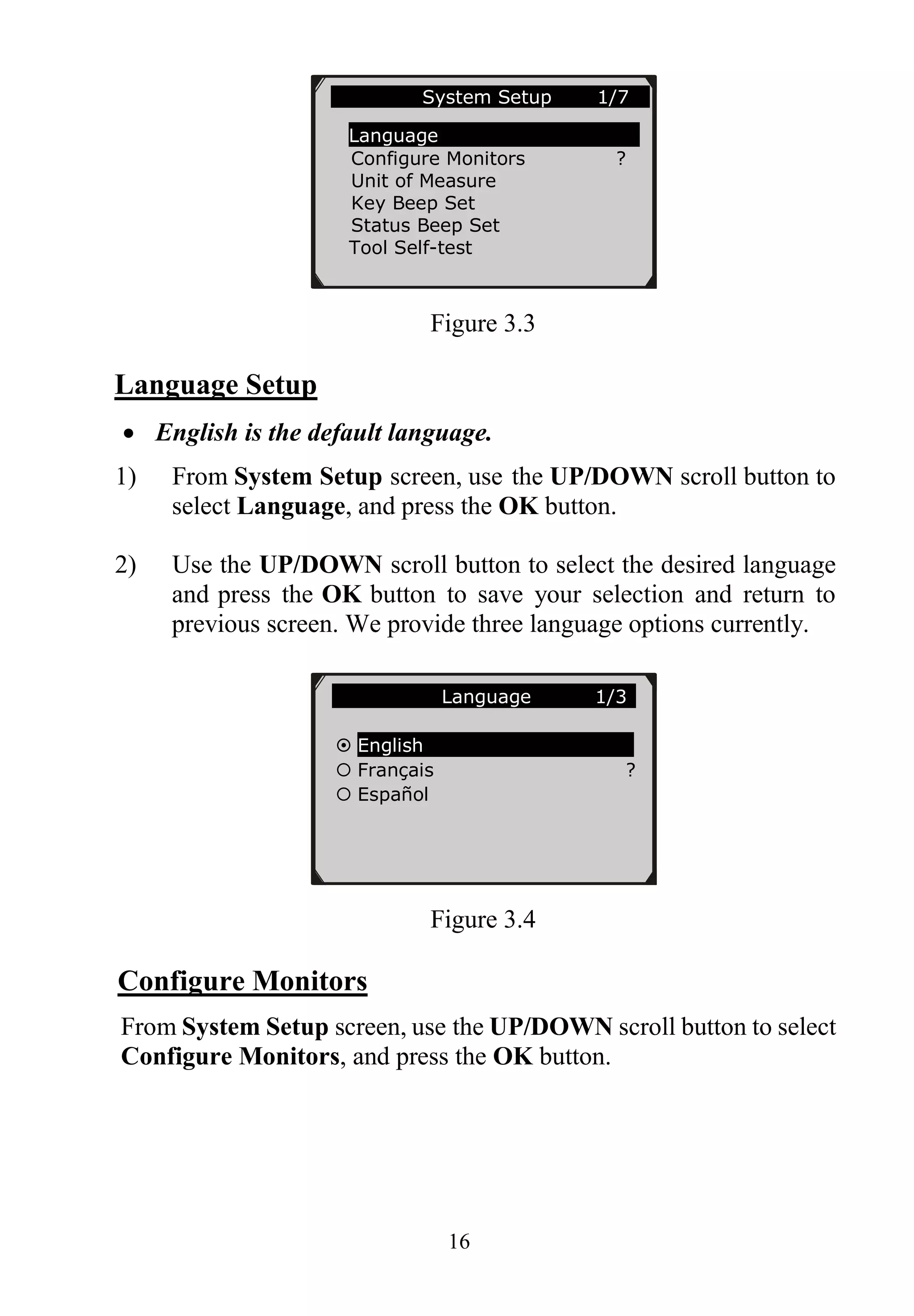
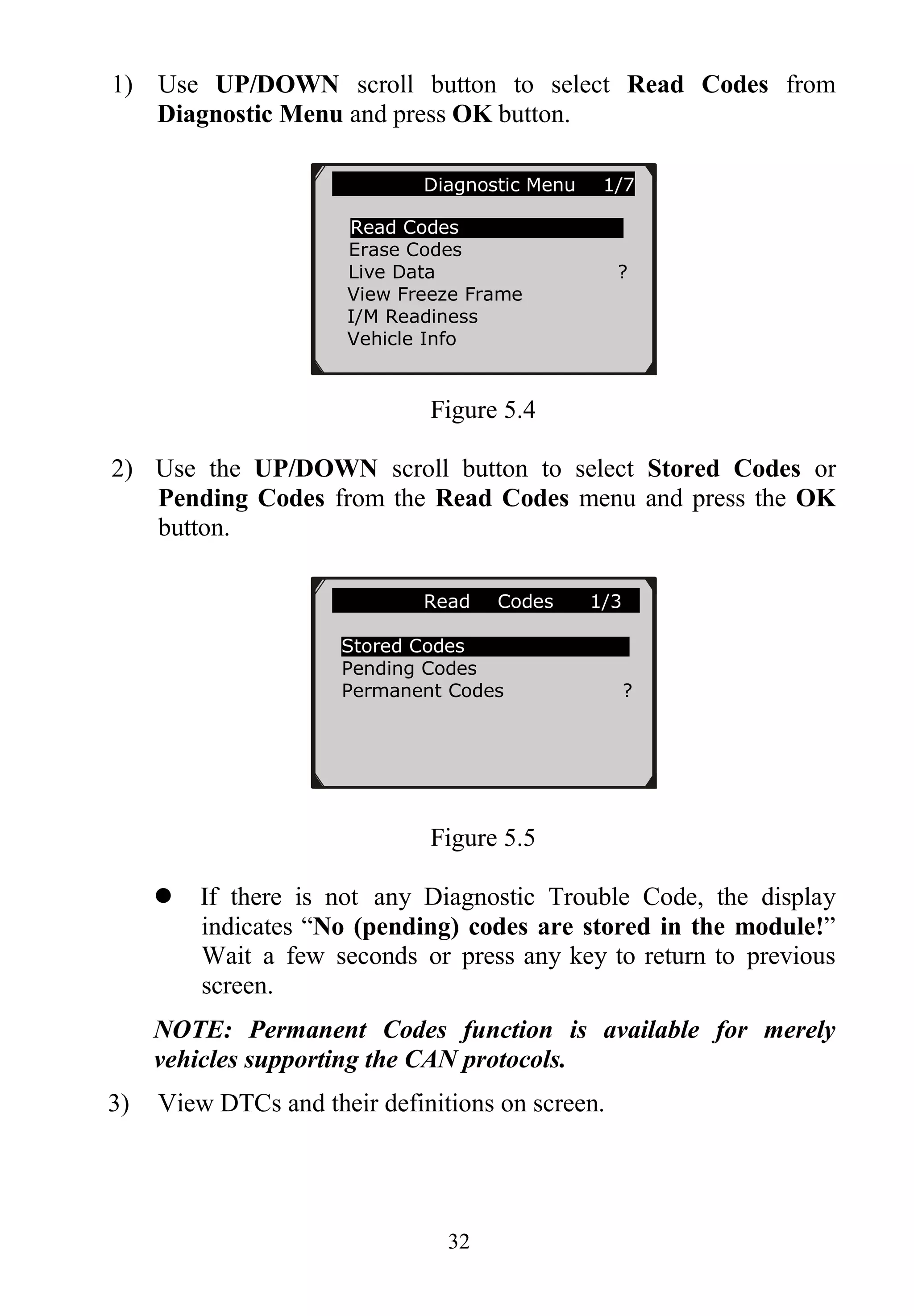
5. OBDII Diagnostics
When more than one vehicle control module is detected by the
scan tool, you will be prompted to select the module where the
data may be retrieved. The most often to be selected are the
Power train Control Module [PCM] and Transmission Control
Module [TCM].
CAUTION: Don’t connect or disconnect any test equipment with
ignition on or engine running.
1) Turn the ignition off.
2) Locate the vehicle‟s 16-pin Data Link Connector (DLC).
3) Plug the scan tool cable connector into the vehicle‟s DLC.
4) Turn the ignition on. Engine can be off or running.
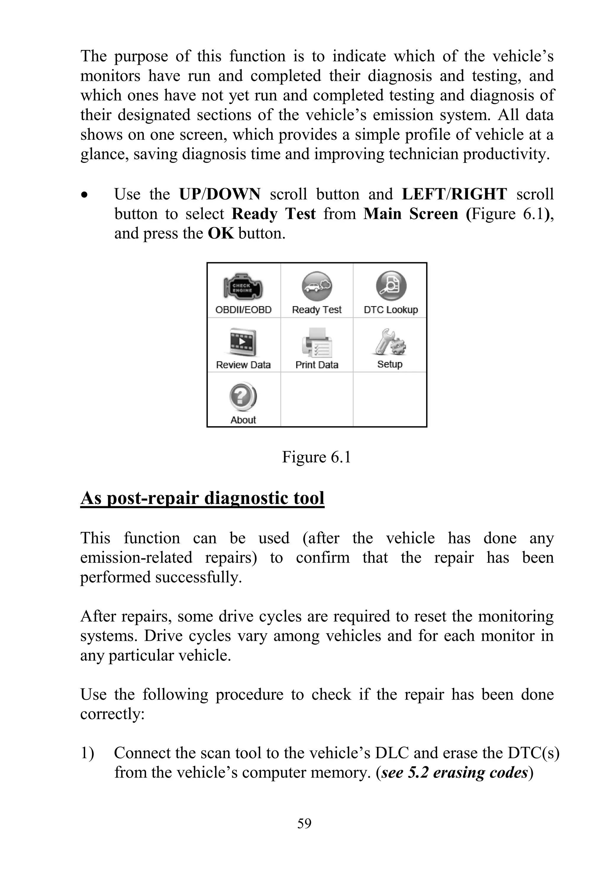
5) Turn on the scan tool. Use the UP/DOWN scroll button to select
OBDII/EOBD from the Main Screen (Figure 3.1).
6) Press the OK button to wait for the Menu to appear. A sequence
of messages displaying the OBDII protocols will be observed on
the display until the vehicle protocol is detected.
If the scan tool fails to communicate with the vehicle’s
ECU (Engine Control Unit) more than three times, a
“LINKING ERROR!” message shows up on the display.
Verify that the ignition is ON;
Check if the scan tool‟s OBD II connector is securely
connected to the vehicle‟s DLC;
Verify that the vehicle is OBD2 compliant;
Turn the ignition off and wait for about 10 seconds. Turn the
ignition back to on and repeat the procedure from step 5.
If the “LINKING ERROR” message does not go away,
then there might be problems for the scan tool to
communicate with the vehicle. Contact your local
distributor or the manufacturer’s customer service
department for assistance.
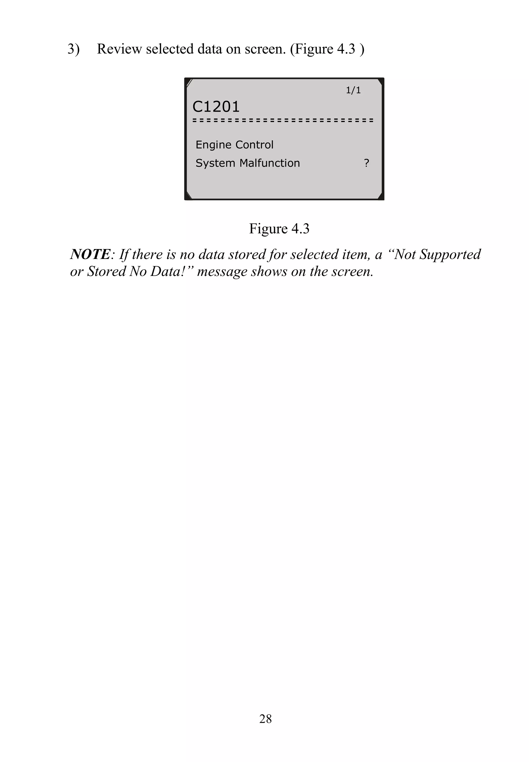
7) You will be prompted to erase previously stored data. (Figure
5.1)](https://image.slidesharecdn.com/autel-autolink-al419-user-manual-140823232733-phpapp01/75/Autel-Autolink-Al419-User-Manual-30-2048.jpg)
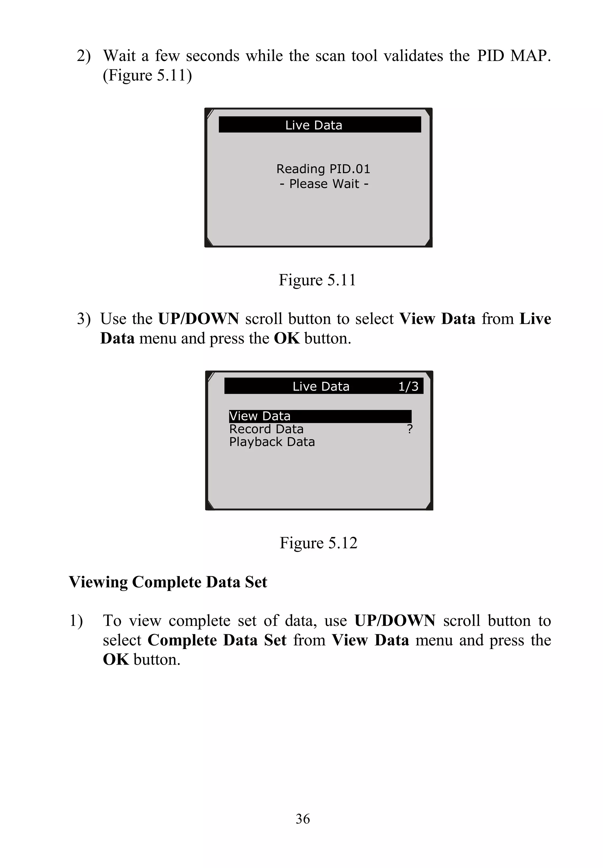
![38
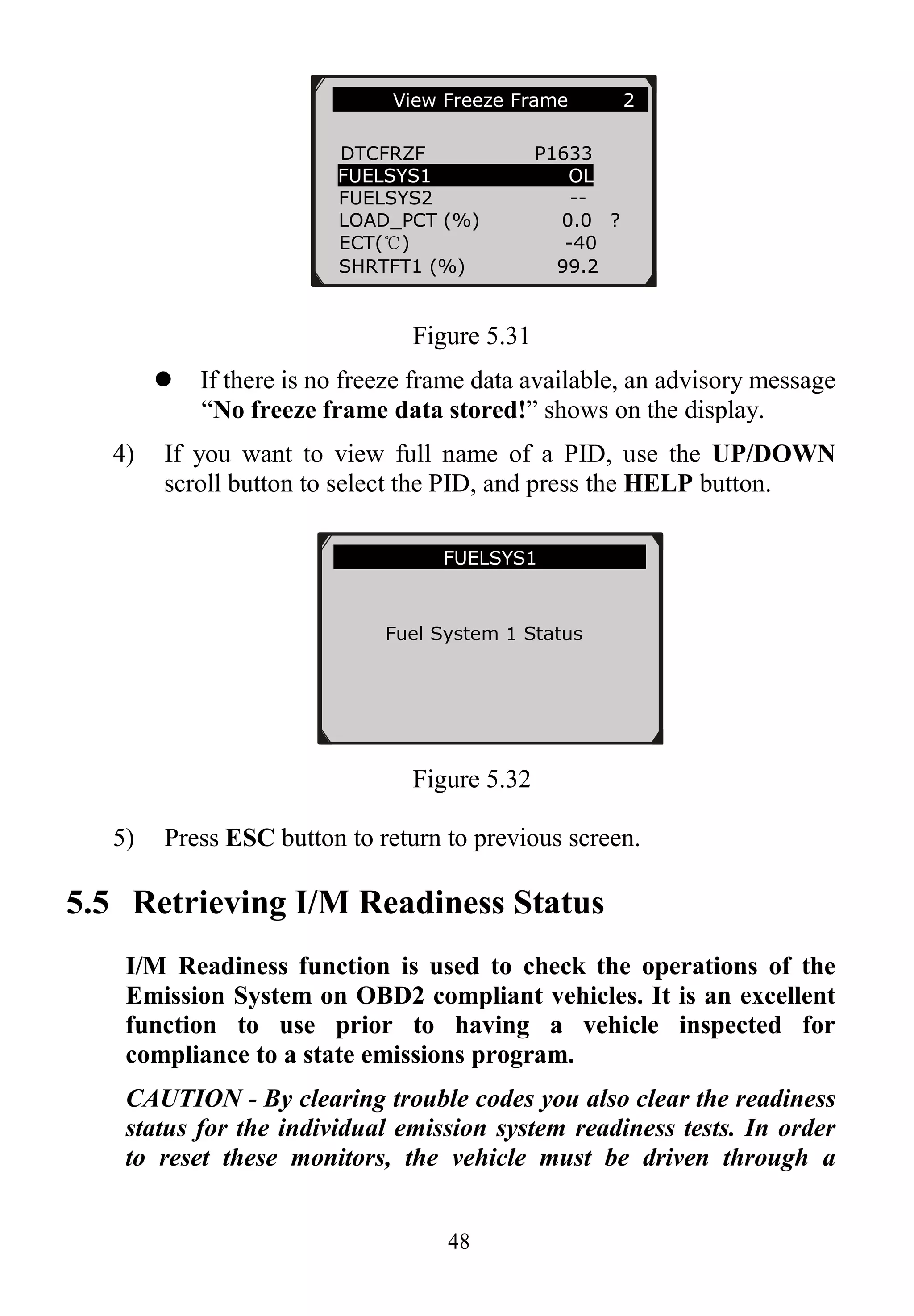
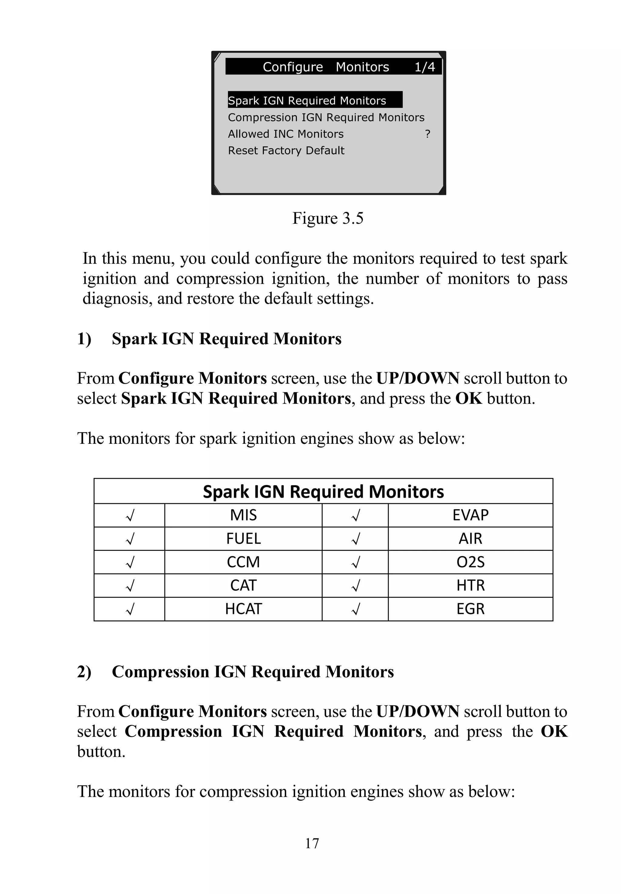
Figure 5.15
3) Press the ESC button to return to previous menu.
Viewing Custom Data Set
1) To view customized PID data, use the UP/DOWN scroll button
to select Custom Data Set from View Data menu and press the
OK button. (Figure 5.13)
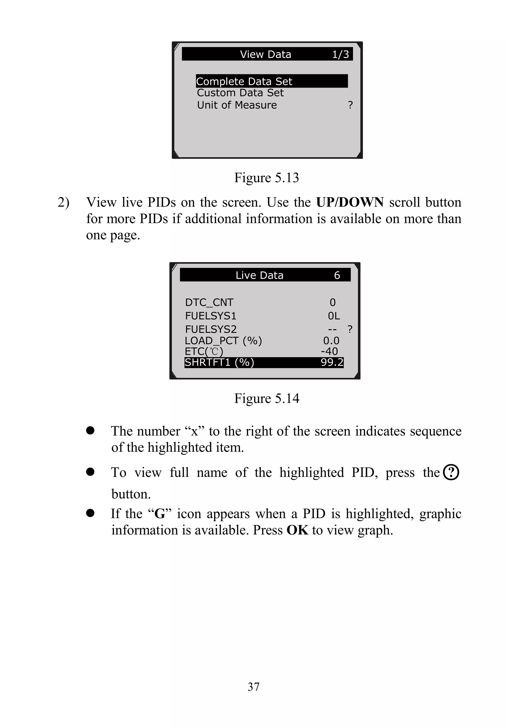
2) Observe on-screen instructions.
Figure 5.16
3) Use the RIGHT button to deselect/select data parameters, and
use the UP/DOWN scroll button to move up and down. Selected
parameters are marked with solid squares.
……………Custom Data Set……… …..
[ ] – Select/Deselect
[ ] – Deselect all
[OK] – Confirm
[ESC] – Cancel
Press any key to continue.](https://image.slidesharecdn.com/autel-autolink-al419-user-manual-140823232733-phpapp01/75/Autel-Autolink-Al419-User-Manual-39-2048.jpg)
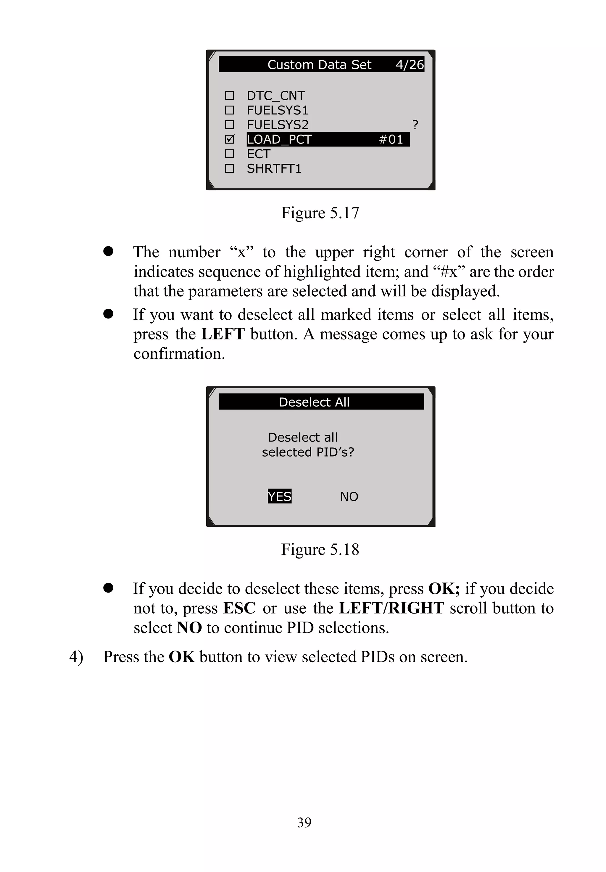
![42
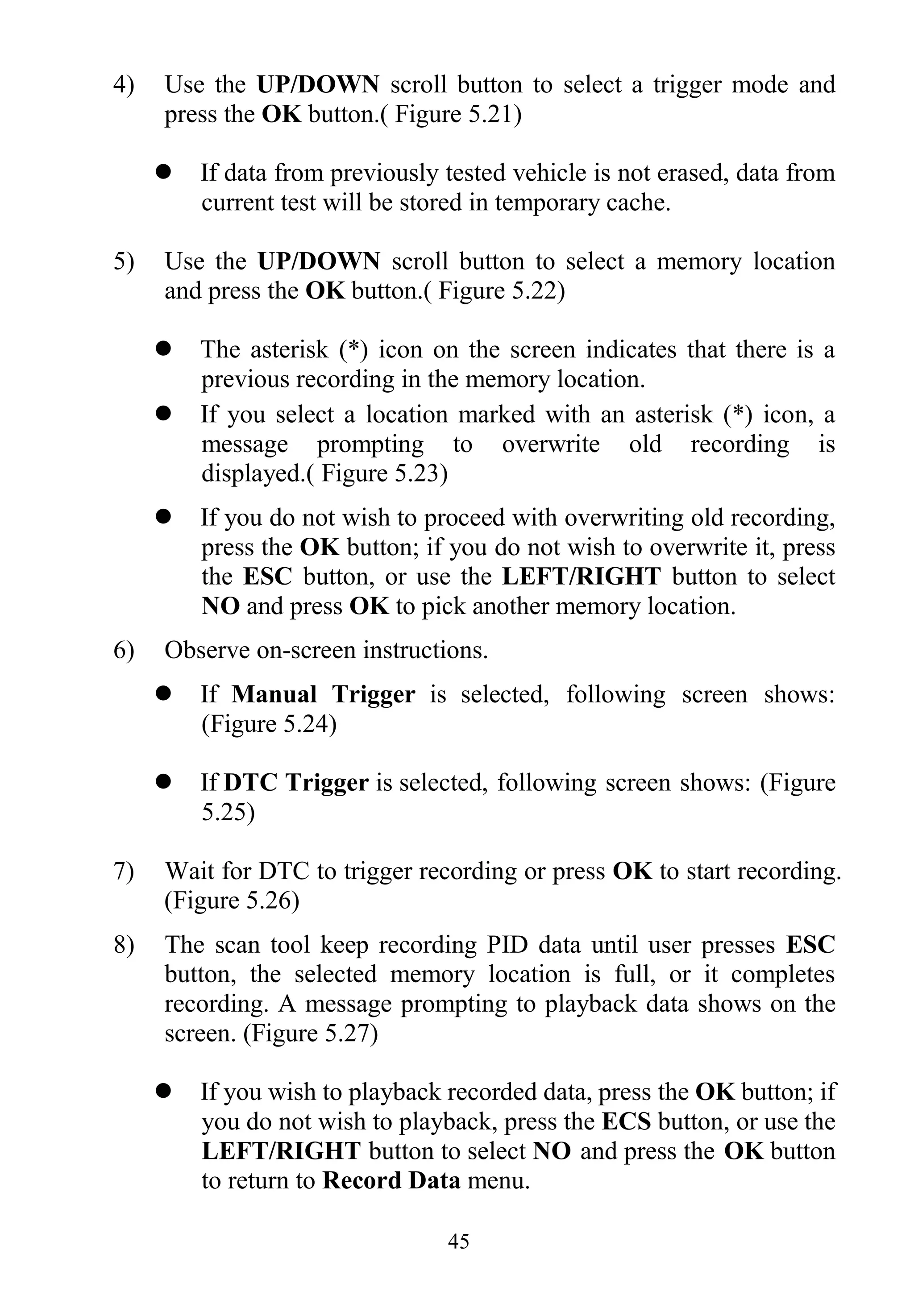
The asterisk (*) icon on the screen indicates that there is a
previous recording in the memory location.
If you select a location marked with an asterisk (*) icon, a
message prompting to overwrite old recording displays.
Figure 5.23
If you wish to proceed with overwriting the old recording,
press the OK button; if you do not wish to overwrite it, use
the LEFT/RIGHT button to select NO or press the ESC
button to pick another memory location.
4) Observe on-screen instructions.
If Manual Trigger is selected, following screen shows:
Figure 5.24
If DTC Trigger is selected, following screen shows:
……………Manual Trigger……………...
Ready to record!
Press [ENTER] to
start recording…
Press [ESC] to exit
Select Memory ...
A previous recording
exists! Do you want
to overwrite it?
YES NO](https://image.slidesharecdn.com/autel-autolink-al419-user-manual-140823232733-phpapp01/75/Autel-Autolink-Al419-User-Manual-43-2048.jpg)
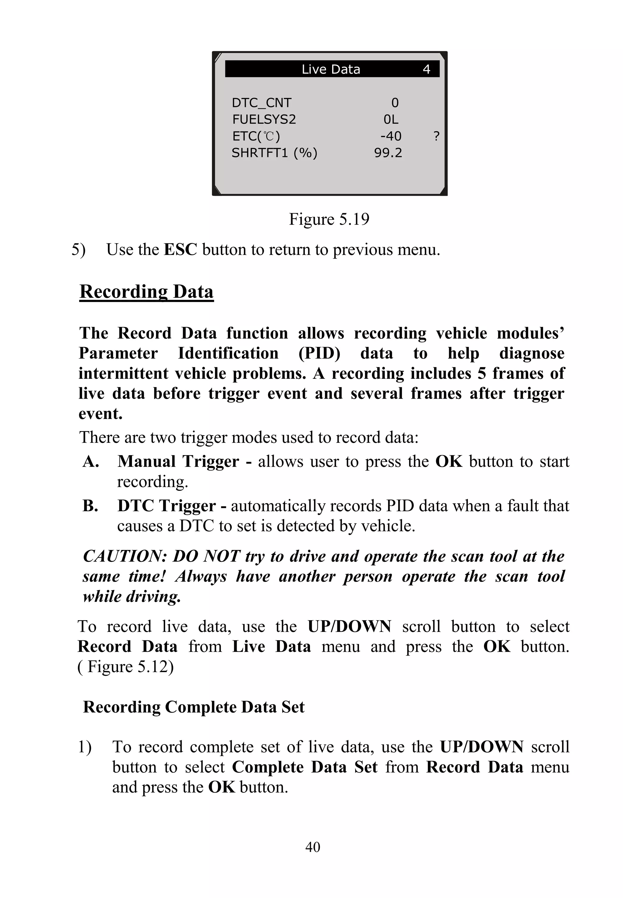
![43
Figure 5.25
5) Wait for DTC to trigger recording or press OK to start recording.
(Figure 5.26)
Drive till a DTC is detected when DTC Trigger is selected. If no
DTCs are detected, press ESC to exit recording.
Figure 5.26
The number “x/x...” to the upper right corner of the screen
indicates the maximum frames that can be recorded and the
number of recorded frames.
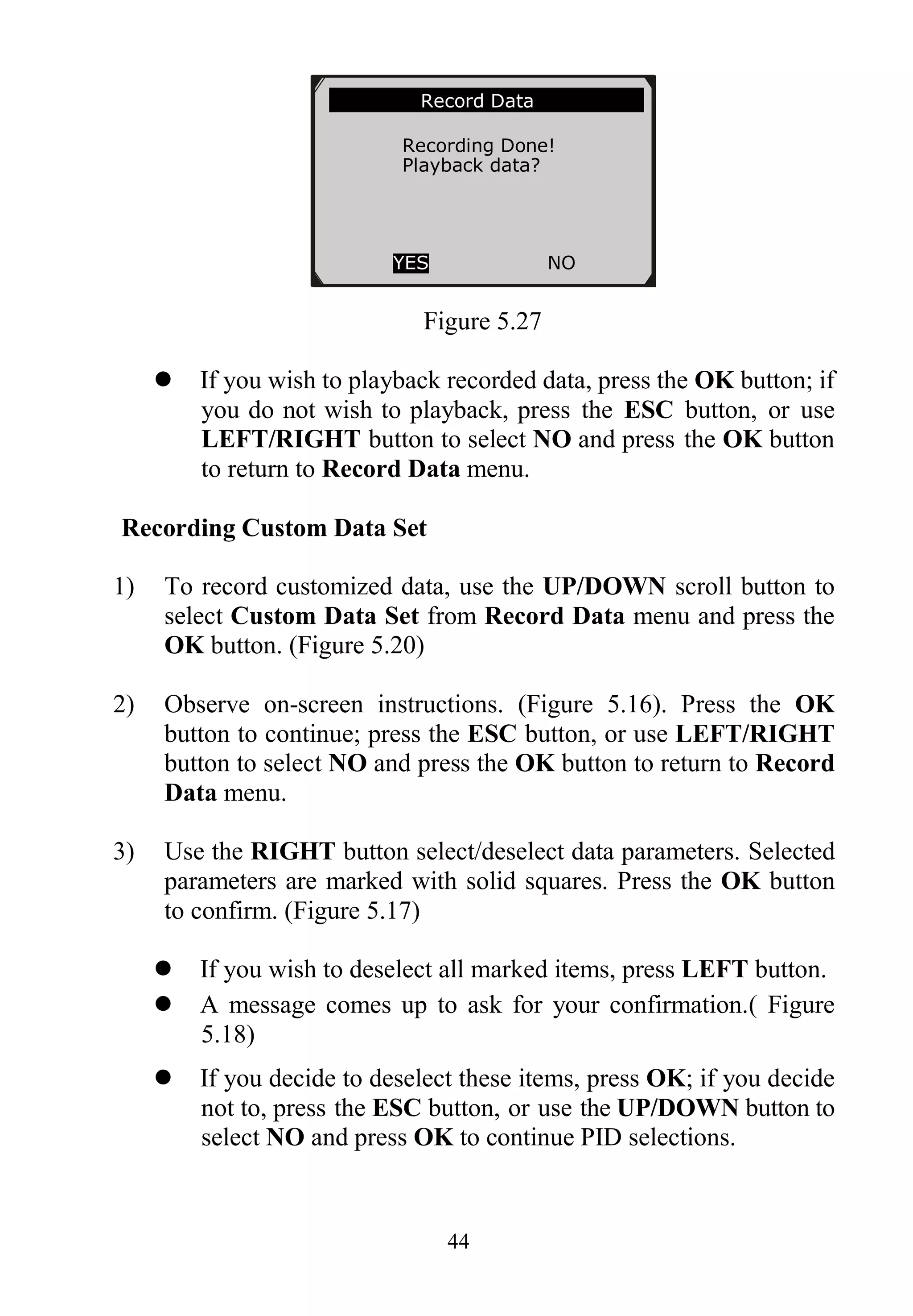
6) The scan tool keeps recording PID data until user presses the
ESC button, selected memory location is full, or it completes
recording. A message prompting to playback data shows on the
screen.
…….Recording…. 5/46 …..
DTC_CNT 0
FUELSYS1 0L
FUELSYS2 -- ?
LOAD_PCT(%) 0.0
ETC(℃) -40
SHRTFT1(%) 99.2
………………….DTC Trigger……………..
Waiting for DTC to
trigger recording…
Press [ESC] to exit](https://image.slidesharecdn.com/autel-autolink-al419-user-manual-140823232733-phpapp01/75/Autel-Autolink-Al419-User-Manual-44-2048.jpg)