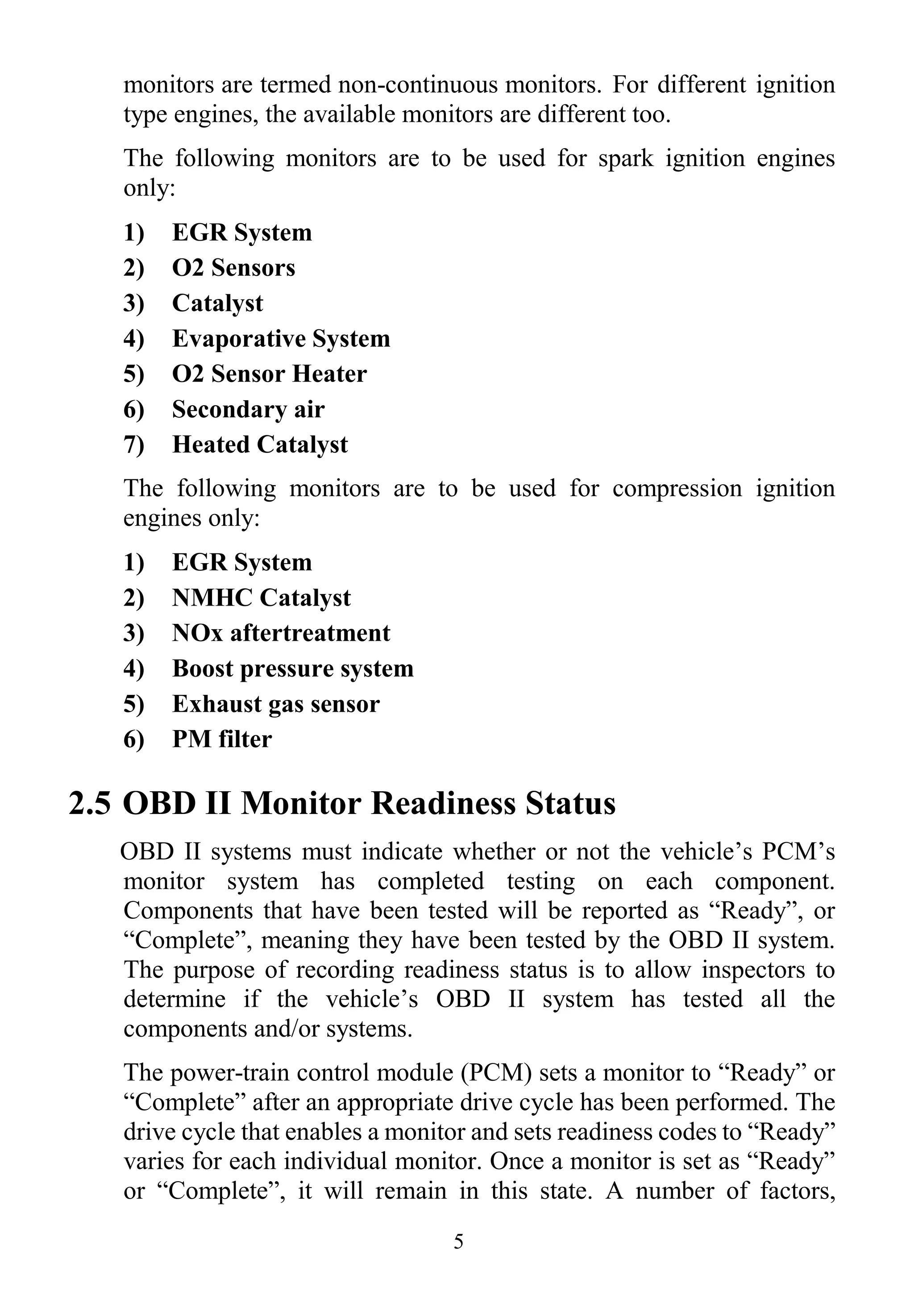
The document outlines essential safety precautions, general information about on-board diagnostics (OBD) II systems, and detailed product information regarding a diagnostic scan tool. It describes the tool's functionalities, including code reading, erasing, live data monitoring, and system setup, along with specifications and included accessories. Additionally, it explains the significance of OBD II readiness monitors, diagnostic trouble codes (DTCs), and operational guidelines for effective vehicle diagnostics.


![19
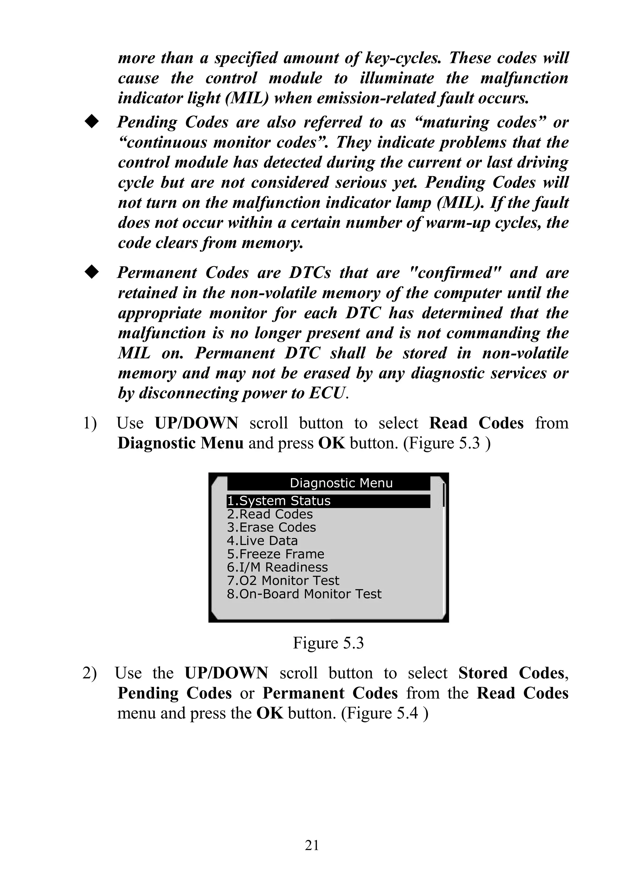
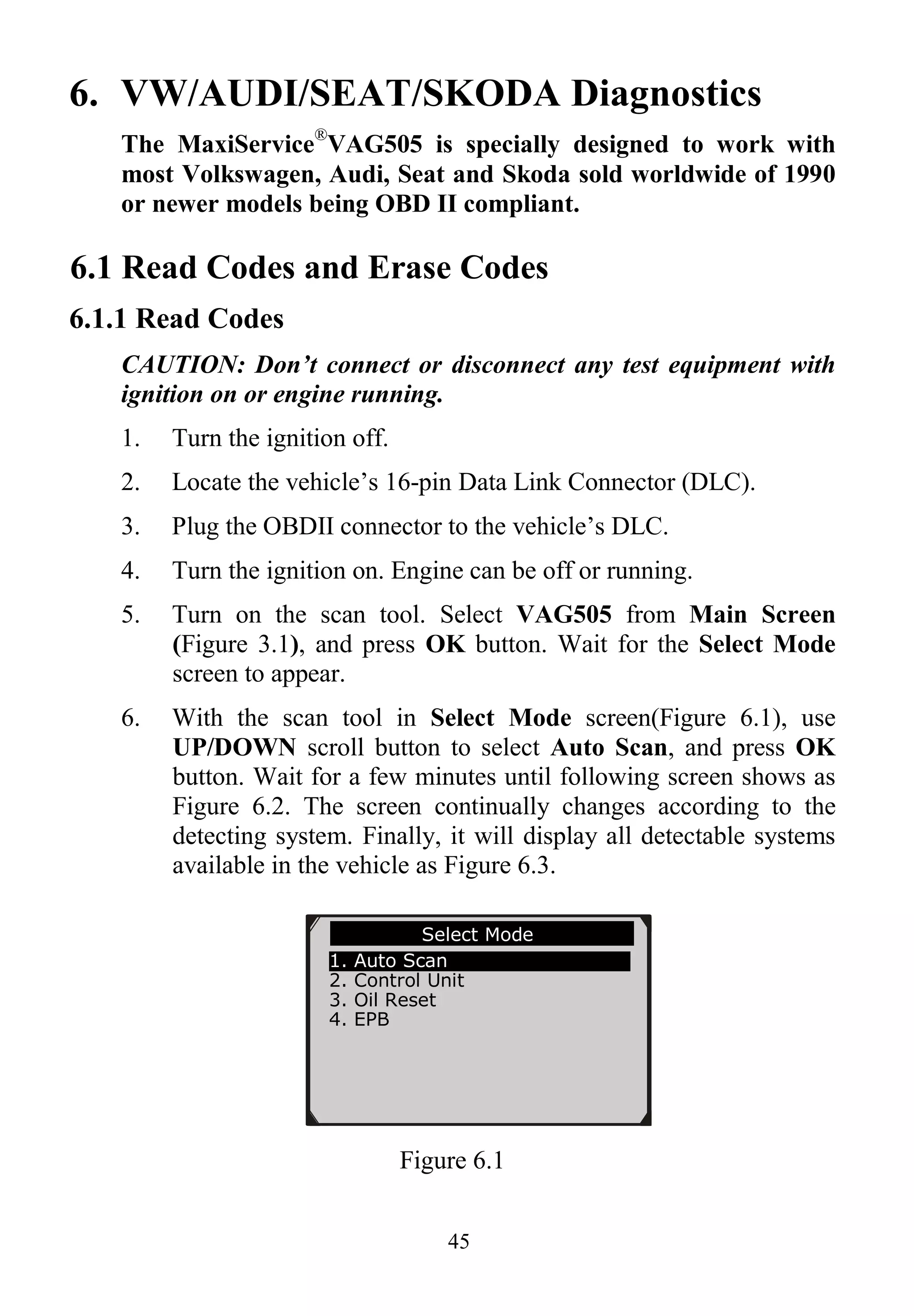
5. OBDII Diagnostics
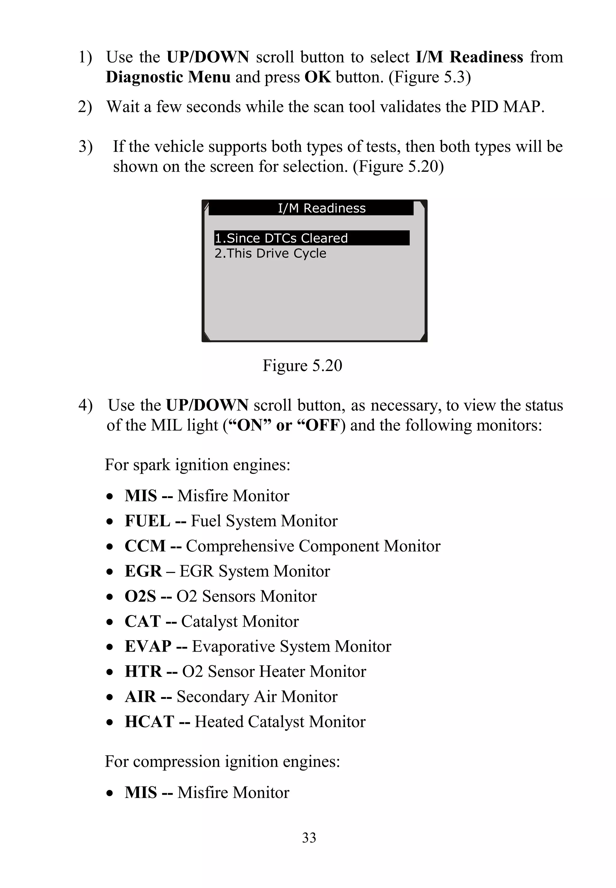
The OBD II Diagnostics function is a fast-access option that allows
you to carry out a quick test on the engine system of OBD II
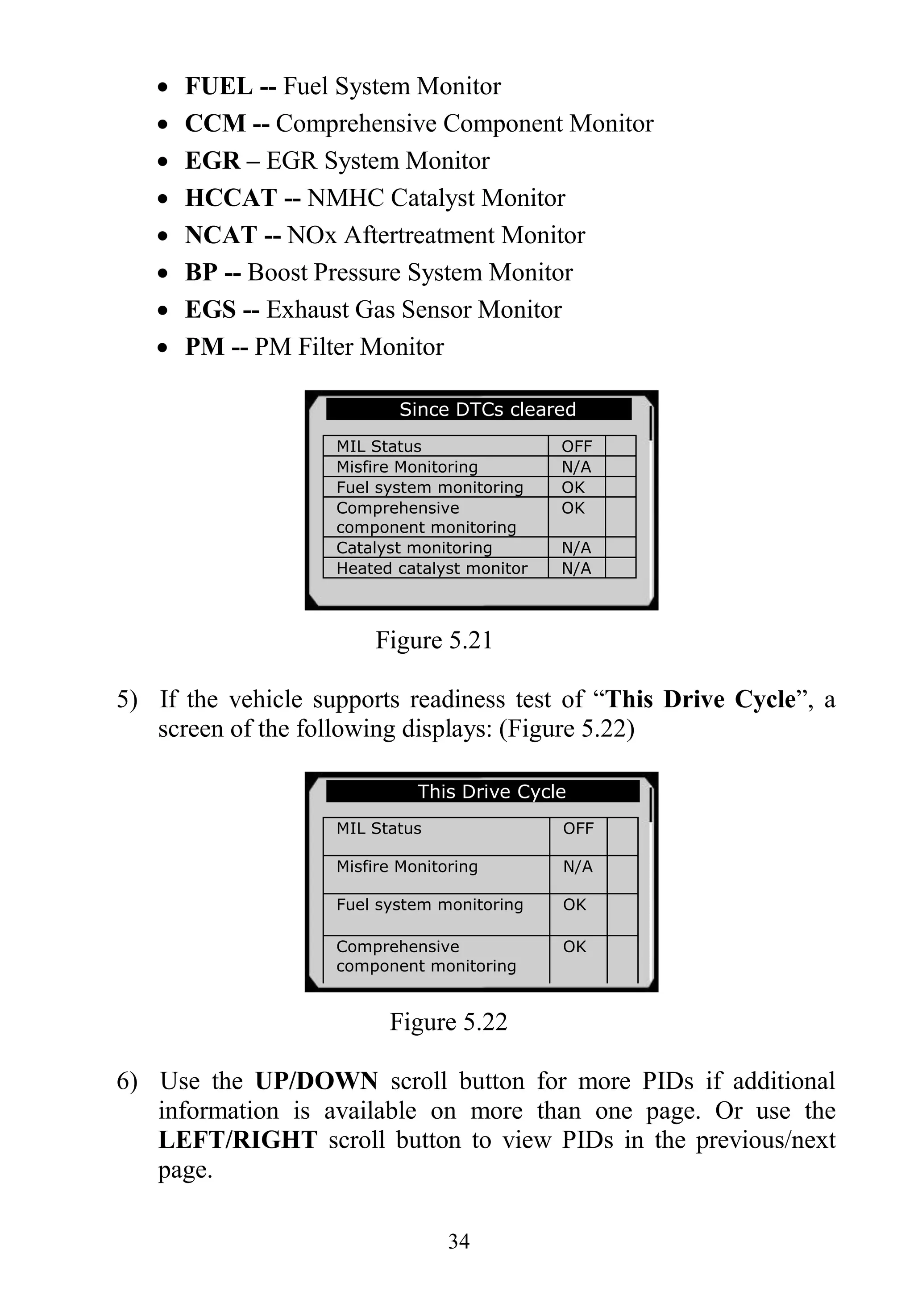
vehicles.
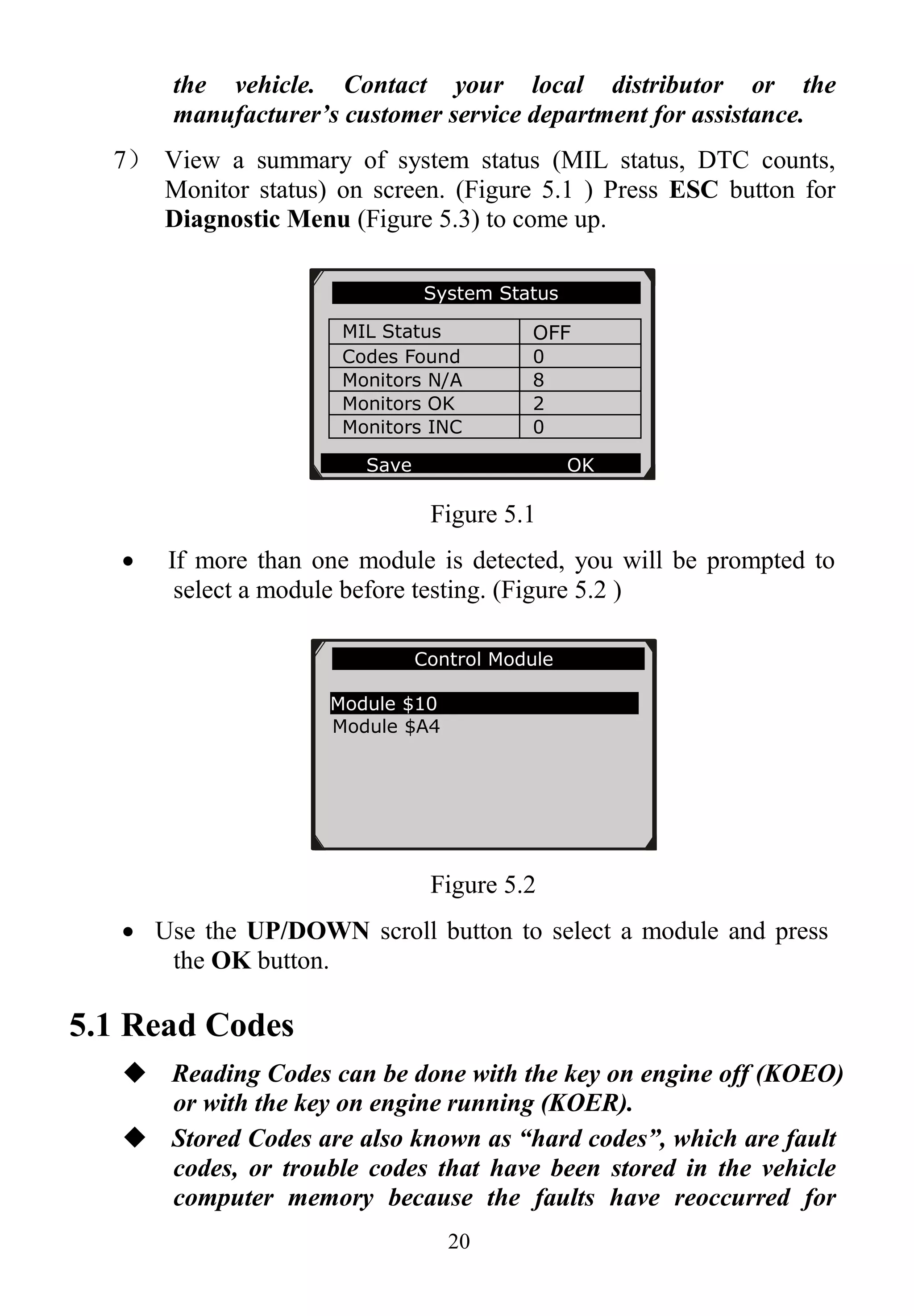
When more than one vehicle control module is detected by the
scan tool, you will be prompted to select the module where the
data may be retrieved. The most often to be selected are the
Power-train Control Module [PCM] and Transmission Control
Module [TCM].
CAUTION: Don’t connect or disconnect any test equipment with
ignition on or engine running.
1) Turn the ignition off.
2) Locate the vehicle’s 16-pin Data Link Connector (DLC).
3) Plug the scan tool cable connector into the vehicle’s DLC.
4) Turn the ignition on. Engine can be off or running.
5) Turn on the scan tool. Select OBDII from the Main Screen.
(Figure 3.1)
6) Press the OK button to wait for the Menu to appear. A sequence
of messages displaying the OBDII protocols will be observed
on the display until the vehicle protocol is detected.
If the scan tool fails to communicate with the vehicle’s ECU
(Engine Control Unit) more than three times, a “LINKING
ERROR!” message shows up on the display.
Verify that the ignition is ON.
Check if the scan tool’s OBD II connector is securely
connected to the vehicle’s DLC.
Verify that the vehicle is OBD2 compliant.
Turn the ignition off and wait for about 10 seconds. Turn the
ignition back to on and repeat the procedure from step 5.
If the “LINKING ERROR” message does not go away, then
there might be problems for the scan tool to communicate with](https://image.slidesharecdn.com/autel-maxiservice-vag505-user-manual-140823234743-phpapp01/75/Autel-Maxiservice-Vag505-User-Manual-21-2048.jpg)
![56
Figure 6.23
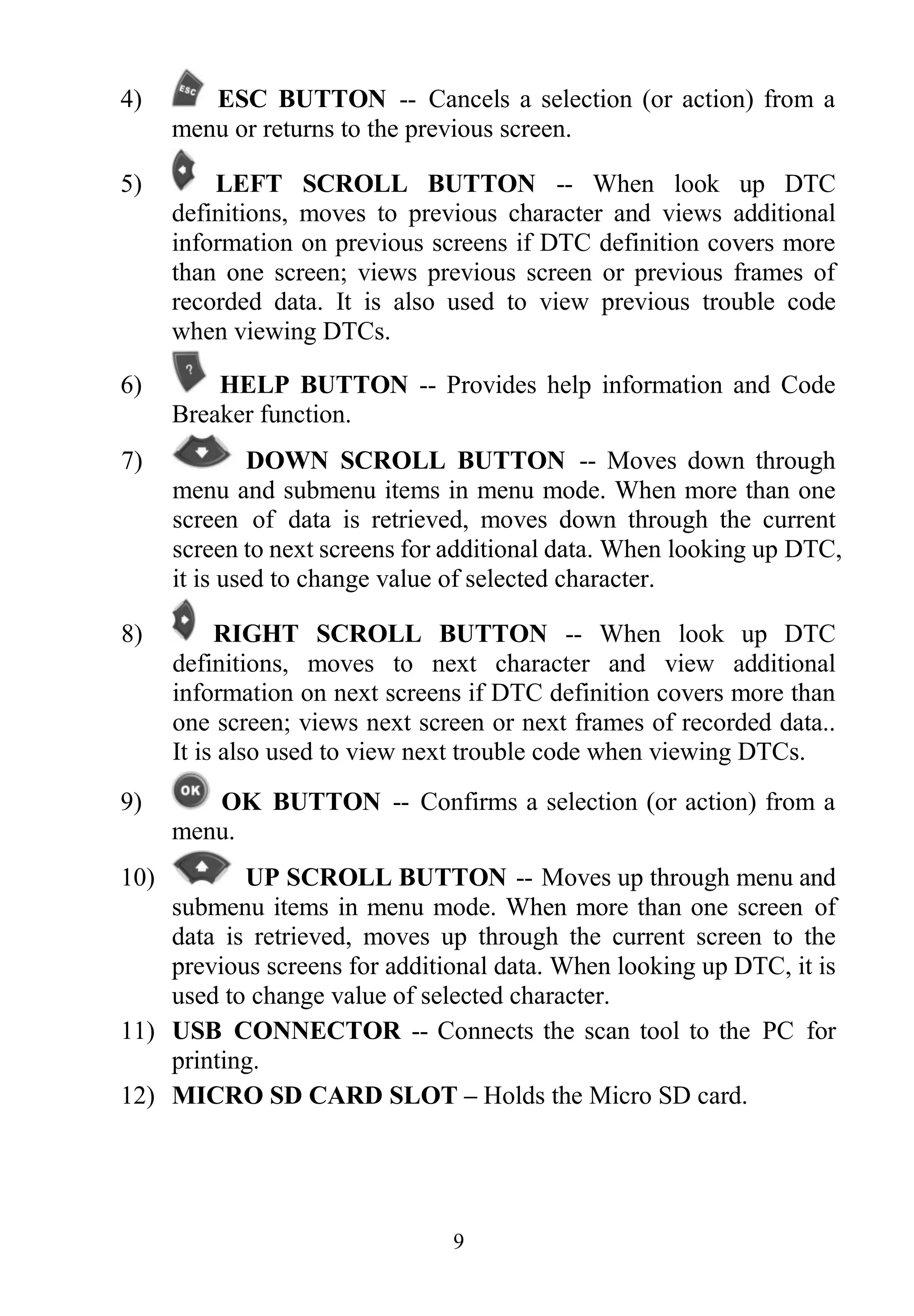
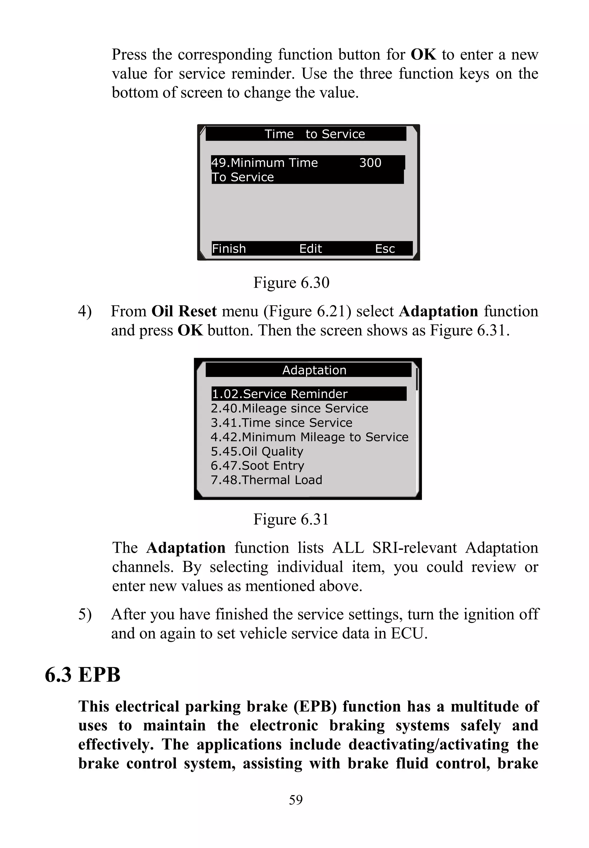
Press the corresponding function button for OK to enter a new
value for service reminder. Use the three function keys on the
bottom of screen to change the value.
Figure 6.24
The three keyboard function keys work as below.
[ Finish ] : After entering a new value, use this key to save the
value to the ECU.
[ Edit ] : Press this key to pop up a soft keyboard to facilitate
your input. (Figure 6.25)
[ Esc ] : Press this key to exit.
Service Reset
Channel/Description Cur Val Unit
02.Service Reminder 0
40.Service since
Mileage
100km 0
41.Time since Service Day(s) 0
ESC OK
Service Reset
02.Service Reminder 0
Finish Edit Esc](https://image.slidesharecdn.com/autel-maxiservice-vag505-user-manual-140823234743-phpapp01/75/Autel-Maxiservice-Vag505-User-Manual-58-2048.jpg)
![57
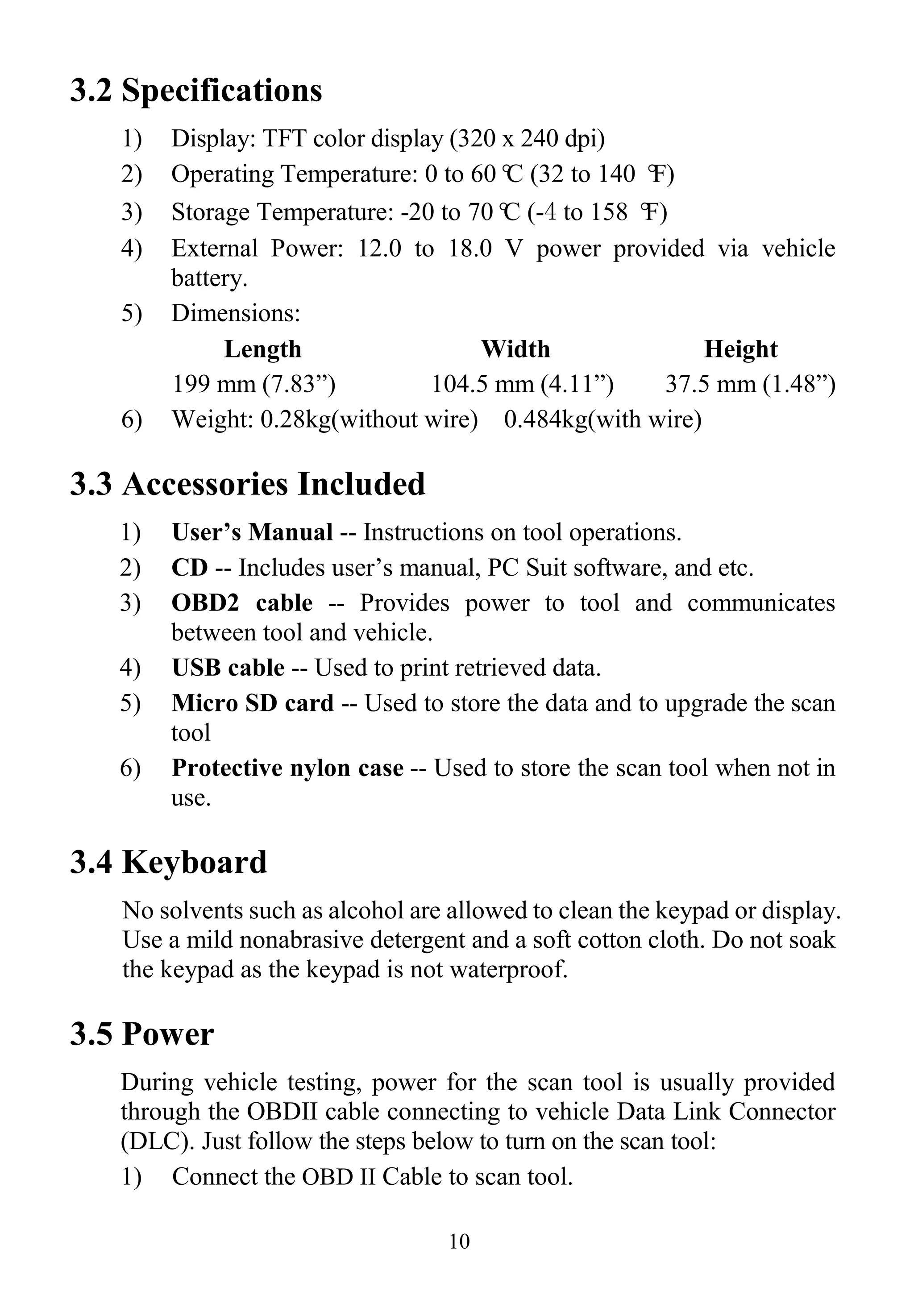
Figure 6.25
The three keyboard function keys work as below.
[Finish] --- When you finished the input, select this key to
confirm your input and exit.
[Pre.] --- Moves a space to the left.
[Backspace] --- Uses this key to erase the previous digit or
character when typing.
NOTE: The data you input must be in the reasonable range,
which is defined by the preset values in ECU. If you enter a data
out of range, the tool will display a warning message.
Figure 6.26
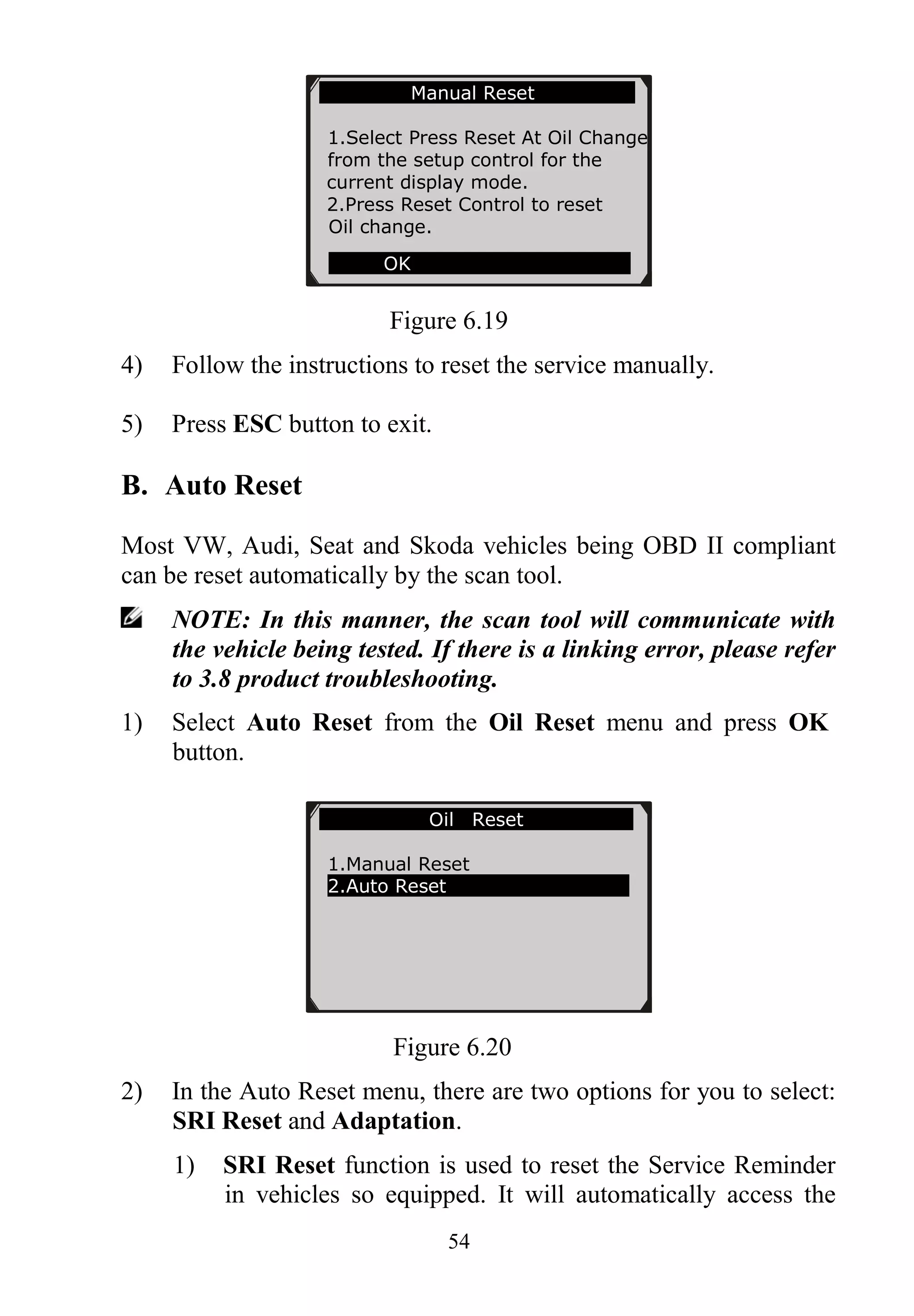
B. From SRI Reset menu (Figure 6.22), select Mileage to Service
function and press OK button. The screen will display the
preset maintenance information of the vehicle. The information
items vary with different vehicles. (Figure 6.27)](https://image.slidesharecdn.com/autel-maxiservice-vag505-user-manual-140823234743-phpapp01/75/Autel-Maxiservice-Vag505-User-Manual-59-2048.jpg)
![67
Figure 6.44
The three keyboard function keys work as below.
[ Finish ] : After entering a new value, use this key to save the
value to the ECU.
[ Show ] : Press this key to pop up a soft keyboard to facilitate
your input. (Figure 6.45)
[ Esc ] : Press this key to exit.
3) Select Show and a soft keyboard will pop up. Use
LEFT/RIGHT scroll button and UP/DOWN scroll button to
move to the desired character.( Take 5 as an example)
Figure 6.45
The three keyboard function keys work as below.
[Finish] --- When you finished the input, select this key to
confirm your input and exit.
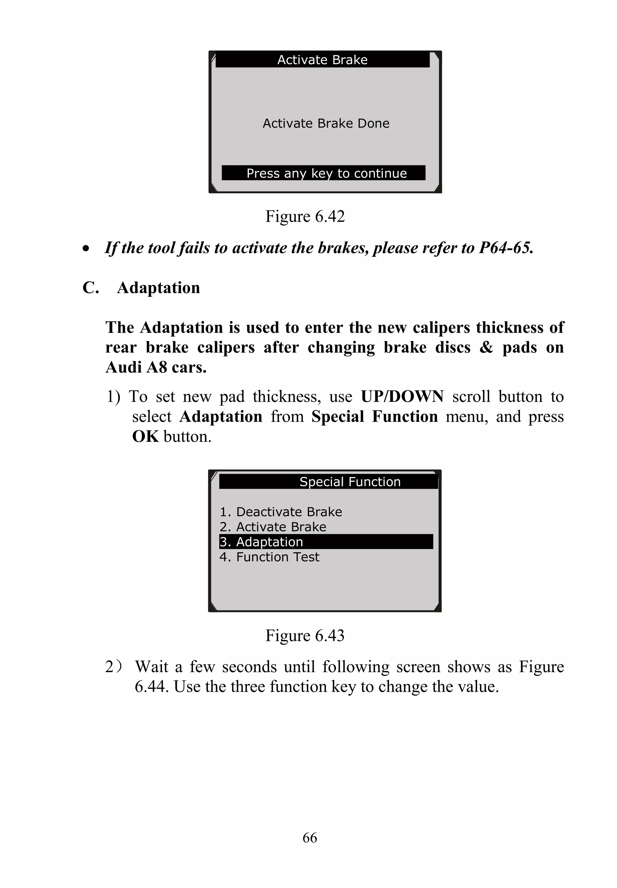
Adaptation
Input the Brake Pad’s thickness of you
want. The value must be between 3 and 14
mm.
Finish Show Esc](https://image.slidesharecdn.com/autel-maxiservice-vag505-user-manual-140823234743-phpapp01/75/Autel-Maxiservice-Vag505-User-Manual-69-2048.jpg)
![68
[Pre.] --- Moves a space to the left.
[Backspace] --- Uses this key to erase the previous digit or
character when typing.
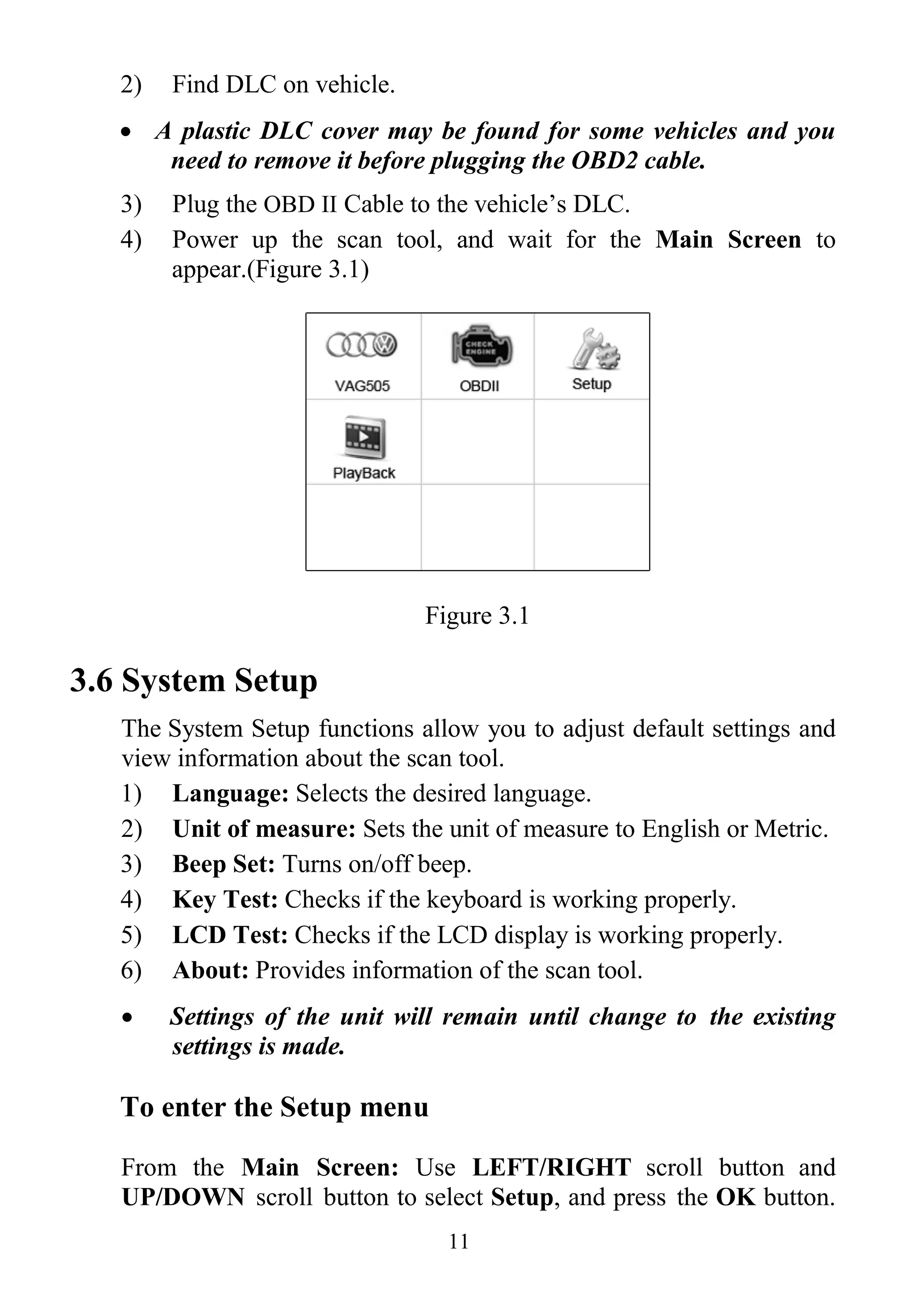
4) After you have input the value, press Finish. A message will
come up asking your confirmation.
Figure 6.46
7) Press Yes function key or OK button, an “Adaptation
Done!” message comes up.
Figure 6.47
NOTE: The data you input must be between 3 and 14mm. If you
enter a data out of range, the tool will display a warning
message to remind you to change the value.
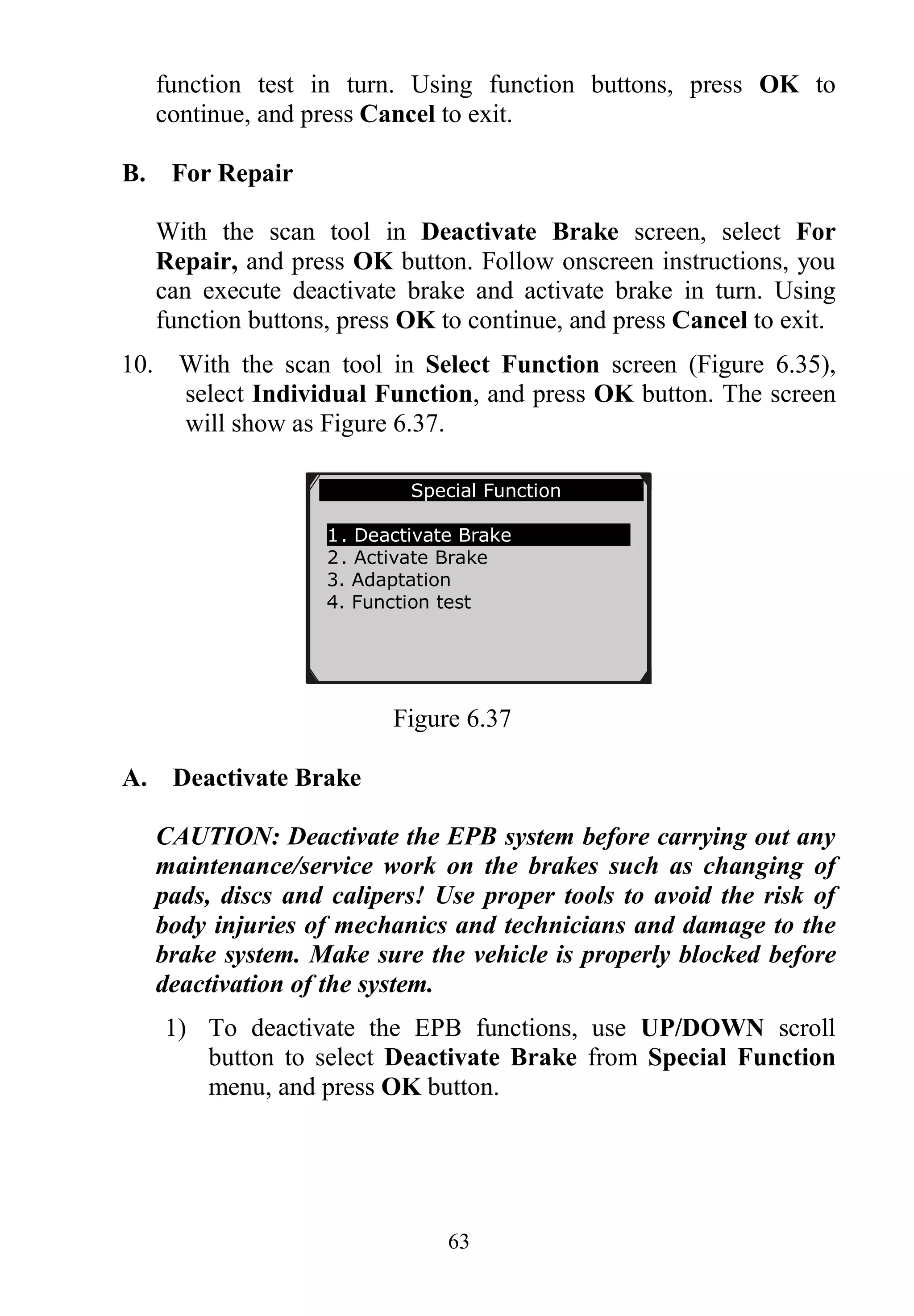
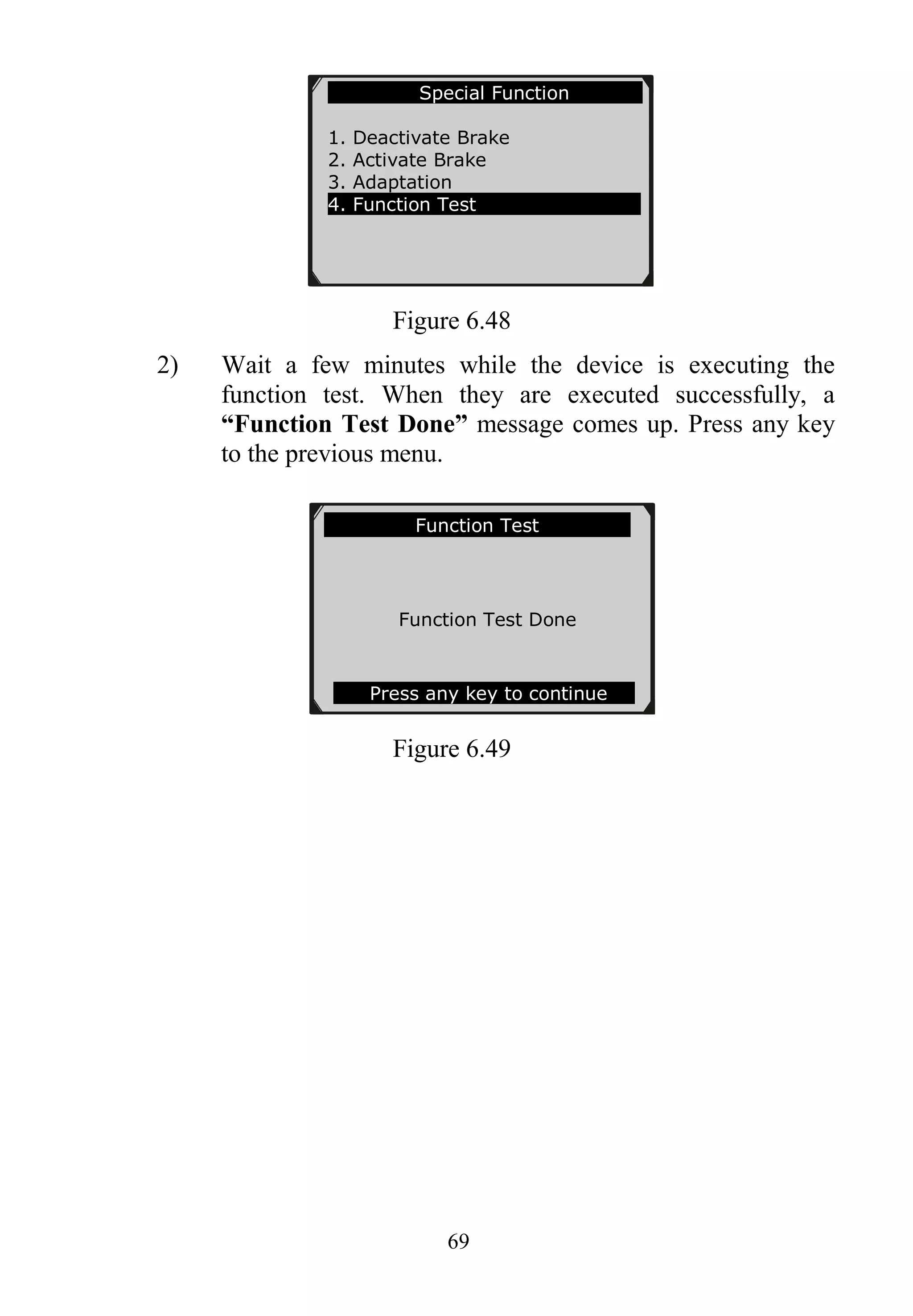
D. Function test
1) With the scan tool in Special Function screen, select
Function Test and press OK button.
Adaptation
Adaptation Done
Press any key to continue
Input Dialog Box
5
Do you want to save and continue?
Yes NO](https://image.slidesharecdn.com/autel-maxiservice-vag505-user-manual-140823234743-phpapp01/75/Autel-Maxiservice-Vag505-User-Manual-70-2048.jpg)
![73
4. Connect the Micro SD card to computer with a card reader.
5. Run the update option in PC Suit software. Wait for the Log In
window to pop up. (Figure 7.3)
Figure 7.3
6. Put in the user name and password and wait for the Update
window to display. If you forget your password unintentionally,
you may always click the [Forget your password?] to link to
our website and find your password back.
7. In the Update window, select the items you want to install.
Usually, you should install all available updates.
Figure 7.4
Generally, there are two ways to update programs:](https://image.slidesharecdn.com/autel-maxiservice-vag505-user-manual-140823234743-phpapp01/75/Autel-Maxiservice-Vag505-User-Manual-75-2048.jpg)
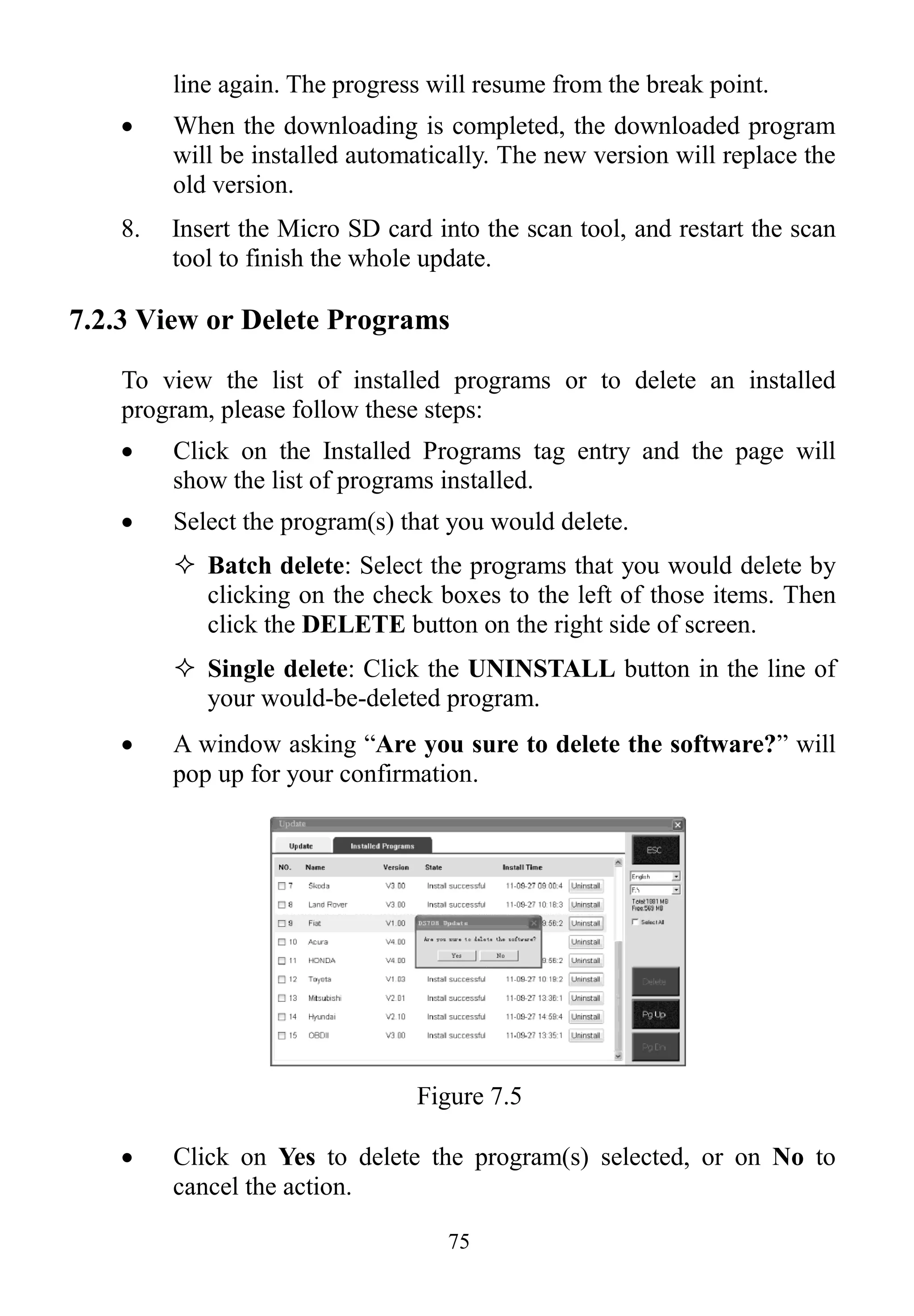
![74
Batch updating
Select the programs that you would update by clicking on the
check boxes next to those items. Then click the Update
Selected Items button on the right side of screen.
Or, click on the SELECT ALL checkbox on the right side of
screen and all updatable items will be selected automatically.
Then click the Update Selected Items button on the right side
of screen.
Check the updating process by observing the upper left progress
bar [downloading] and upper right progress bar [installing]. You
may also find progress information in the Status column of
updated items.
Anytime you could click the Pause button on the right side of
screen to suspend all progresses, and the state of those
suspended items would change to STOPPED.
To resume updating process, you may need to select those
suspended items again, then click the Update Selected Items
button. The progress will resume from the break point.
When the downloading is completed, the downloaded programs
will be installed automatically. The new version will replace the
old version.
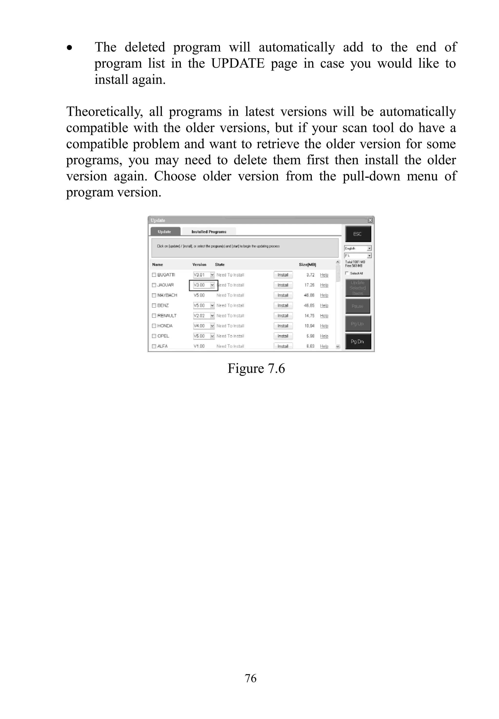
Single updating
Find the desired updating item and click the INSTALL button
in the same line. With updating in progress, the INSTALL
button changes to STOP.
Check the updating process by observing the upper left progress
bar [downloading] and upper right progress bar [installing]. You
may also find progress information in the Status column of
updated items.
Anytime you could click the Pause button in the line to suspend
this progress, and the state of this item would change to
STOPPED.
To resume updating process, click the INSTALL button in the](https://image.slidesharecdn.com/autel-maxiservice-vag505-user-manual-140823234743-phpapp01/75/Autel-Maxiservice-Vag505-User-Manual-76-2048.jpg)