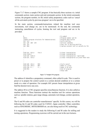
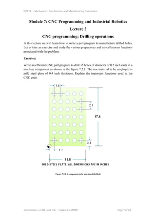
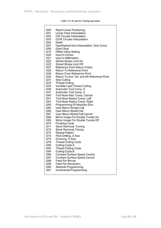
The document discusses CNC programming for drilling operations. It provides a sample CNC program to drill 35 holes of 0.5 inch diameter in a steel plate as shown in the figure. The program uses G-codes and M-codes to perform functions like selecting coordinate systems, tool changes, drilling cycles, and returning to reference positions. It explains the purpose and meaning of each block of code in the sample program.
This document discusses computer integrated manufacturing and CAD/CAM modeling techniques. It introduces wireframe, surface, and solid modeling approaches used in geometric modeling. Wireframe models represent objects with edges, while surface modeling uses surfaces defined by vertices and edges. Solid modeling represents objects as bounded 3D volumes divided space into interior and exterior regions. The document then discusses modeling primitives, drawing entities, and algorithms for drawing lines and circles in computer graphics. It concludes by introducing the concept of representing curves and surfaces through implicit and parametric equations.
The document discusses the history and development of computer numerical control (CNC) machines. It describes how CNC machines evolved from early numerical control machines run by punched cards to modern CNC machines with onboard computers. The document also covers CNC part programs, basic CNC machine components, motion control types, advantages like precision and disadvantages like higher costs compared to manual machines.
This document provides an overview of computer numerical control (CNC) machines. It discusses what NC and CNC are, the history of NC machines, the typical elements of a CNC system including the part program and control unit. It also describes different types of CNC machines such as lathes, mills, drills, and lasers. Advantages of CNC machines include precision, efficiency, and reducing waste, while disadvantages include higher costs.
This document discusses NC part programming for CNC machines. It covers key topics such as manual and computer-aided programming, program language terminology including words, blocks, and syntax, common G and M codes used in programming, and dimensional words for specifying tool movements and positions. It also provides examples of programming safety rules and an overview of the CNC programming process.
The document discusses CNC programming and provides an example program for drilling holes. It begins with an overview of CNC programming fundamentals such as the structure of CNC programs and common G and M codes. It then presents a sample drilling program that rapid positions the tool, activates drilling and coolant functions, and uses a canned cycle to efficiently drill 35 holes in a specified pattern. The summary provides the high-level purpose and key elements like canned cycle use while keeping within the 3 sentence limit.
Numerical control (NC) is a form of programmable automation that uses coded alphanumeric data to control the mechanical actions of machine tools. This data represents positions of the workhead and workpart and other instructions. Early NC used punched paper tape to store programs, but later computer numerical control (CNC) added memory and allowed programs to be written at a computer terminal. CNC equipment consists of a machine control unit that stores and executes part programs to control processing equipment like machine tools. Part programs contain instructions for tool positions, speeds, and other functions to transform a workpiece.
This document provides an introduction to computer numerical control (CNC) technology and metal cutting. It discusses the history of CNC development from the first numerically controlled machine in 1949 to modern CNC machines found in many industries today. The key components of a CNC system are described, including the part program, program input device, machine control unit, drive system, machine tool, and feedback system. Common CNC machine tools and their applications in industries like automotive and aerospace are also outlined.
This document describes a CNC milling machine training program presented by Gitanshu Kumar. It includes sections on the evolution of NC machines, types of CNC machines and controls, data input methods, operational features of CNC machines, features of CNC milling, tools used, cut viewer software, programming letters and codes, and an example CNC program. Advantages of CNC machines include high repeatability, precision, and productivity while disadvantages include high setup costs and needing skilled operators.
The document describes an industrial training institute that offers a 24-week CNC machining and programming course. The course covers topics like CNC turning, milling, programming using Fanuc and Siemens controllers, tooling, safety procedures, and more. It is aimed at candidates with qualifications in mechanical/production fields and includes both theoretical and practical training.
The document discusses various topics related to manufacturing processes including conventional and non-conventional machining processes, CNC machining, cutting speeds, feeds, tool offsets, programming codes and functions. It provides information on different machine tools, machining centers, transducers and controllers used in manufacturing. Cutting speed and feed rate tables are included for a variety of materials.
This document provides an overview of computer numerical control (CNC) machines. It defines NC and CNC, describes the history and typical elements of a CNC system, and discusses different types of CNC machines and their applications. The key components of a CNC system are the part program, program input device, machine control unit, drive system, machine tool, and feedback system. Common types of CNC machines include lathes, mills, drills, boring machines, and grinders, which are used across industries like automotive, aerospace, and machinery manufacturing. Advantages of CNC include precision, reduced waste, and the ability to operate machines continuously.
The document provides an introduction to computer aided manufacturing (CAM) and numerical control (NC) systems. It defines CAM as using computer programs to generate tool paths for machining parts. It then defines NC as a form of programmable automation where a machine's mechanical actions are controlled by a coded program. The basic components of an NC system are described as the program of instructions, machine control unit, and processing equipment. Different types of NC machines like horizontal machining centers (HMC) and vertical machining centers (VMC) are also summarized.
This document discusses CNC (computer numerical control) machining. It covers basic components of a CNC system including the machine control unit and describes part programming methods. It discusses sequential controllers and manual part programming. It also covers tool path generation for rough and finish machining of complex surfaces and quality aspects of CNC machining. References for further reading on the topic are provided at the end.
NC machines are numerically controlled machine tools that are programmed to automatically perform manufacturing operations. The key elements of an NC machine include the part drawing and program, program tape, machine control unit (MCU), and machine tool. The MCU reads and interprets the NC program from the tape or file to control the machine tool's functions like positioning the tool, controlling feed rate and spindle speed, and changing tools. NC machines offer advantages like increased accuracy and productivity compared to manual machine tools.
This document provides information about numerical control (NC) and computer numerical control (CNC) machining. It defines NC as using coded programs to automatically operate machines, with CNC adding an onboard computer. The history of NC is described from its origins in 1947 to modern CNC. Key aspects of CNC systems like controllers, programming, and integrated CAD/CAM are summarized. Other machining techniques like EDM and laser cutting are also briefly outlined.
NC machine tools are controlled by programmed instructions without a human operator. The NC program contains a set of instructions that controls axis motion. The main components of an NC machine are the part program, programming tape, machine control unit, and machine tool. The MCU reads and interprets the program to control the machine tool's functions like spindle speed, tool positioning, and feed rate. NC machines offer benefits like high accuracy, reduced scrap, and increased productivity compared to conventional machining.
1. The document discusses the history and development of CNC (Computer Numerical Control) machines from conventional machines to NC (Numerical Control) machines to CNC machines.
2. It describes the key elements of an NC system including the machine control unit, machine tool, and part program/drawings.
3. The document provides details on different types of CNC machines based on their motion type (point-to-point vs continuous path systems) and explains fixed and floating zero systems.
The document provides an overview of CNC machine tools and part programming. It discusses the evolution of numerical control from manual machining to computer numerical control. Key developments include the use of paper tape programs, then storing programs in computer memory. The document outlines the typical elements of a CNC system and programming terminology. It also provides examples of CNC machine types and manual part programming.
The document discusses the history and technology of computer numerical control (CNC) machines. It explains that CNC refers to computer-controlled machine tools that can be programmed to automatically perform tasks like cutting, grinding, drilling, and milling materials without manual assistance. The summary provides a high-level overview of the key points covered in the document in 3 sentences:
CNC uses computer software and hardware to control machine tools and automate the manufacturing process, allowing complex and precise parts to be machined without direct human assistance. The technology originated from numerical control systems developed in the 1940s-50s and has since evolved to include computer control of machine tools. CNC machines are now widely used across industries like automotive,
The document provides information about a training on CNC (Computer Numerical Control) machines conducted by the Mechanical Engineering department at GEETANJALI INSTITUTE OF TECHNICAL STUDIES. It discusses the basics of CNC, including the classification of CNC machines, basic elements, programming and process. The training covered topics such as designing software, wheel balancing, CNC lathe machine operation, engine assembly and disassembly, welding and soft skills.
This document provides information about Numerical Control (NC) and Computer Numerical Control (CNC) machines. It discusses:
- The difference between NC and CNC machines, with CNC machines having more advanced computer control capabilities than early NC machines controlled by tape or cards.
- The history and evolution of CNC, starting from early NC machines developed in the 1940s-1950s controlled by punch cards and tape, to the introduction of microprocessors and computers enabling more advanced CNC machines from the 1970s onward.
- Key enhancements provided by CNC over NC include canned cycles, sub-programming, compensation functions, and more complex interpolation capabilities like B-splines.
- CNC
This describes the mechanism of Computer Numerical Control along with its types, control system, motion system, Programming of CNC, G codes, Part programming, adaptive control machining etc.
The document discusses a CNC machine created by Rania hasan and Enas hamadneh. It describes how numerical control allows a machine to operate automatically based on coded instructions. The CNC machine uses a PIC 18 controller and stepper motors to move in the X, Y, and Z axes according to G-code instructions parsed from a program. Safety features like limit switches ensure the machine stops if axes are exceeded. The goal was to make an inexpensive and fast CNC machine capable of drilling designs into wood.
This document discusses computer numerical control (CNC) systems. It begins by defining CNC and describing how numerical data in a part program is translated into electrical signals that control machine tools. It then outlines the history and development of CNC machines. The rest of the document details key aspects of CNC systems including types of CNC machines, machine control units, positioning systems, driving systems, feedback devices, and CNC part programming.
The document provides an overview of CNC (computer numerical control) machines, including their history, components, operation, programming, and advantages. It was presented by Diksha Gangwar at Bharat Heavy Electricals Limited (BHEL) in Haridwar, India. BHEL is a large manufacturer of power generation equipment, including gas turbines, steam turbines, generators, and boilers. The document defines CNC machines, describes their typical components like controllers and automated tool changers, and explains how they work through open and closed loop control systems. It also covers CNC programming basics using G and M codes and highlights the advantages of CNC like increased productivity and consistency as well as challenges like costs and maintenance.
NC and CNC machines are controlled by NC programs that specify tool motions and machining parameters. CNC machines allow complex geometries to be machined with repeatable accuracy in an automated way. The history of CNC began in 1949 with the development of numerically controlled machines. Modern CNC machines use computer controls and feedback systems for precise motion control. NC programs can be manually written in code like RS274D or automatically generated from 3D models.
This document describes a novel technique for controlling CNC systems using Matlab software and an Arduino microcontroller. Matlab is used to process images of parts and convert them into arrays of pixel data representing the geometry. This data is sent via serial communication to an Arduino microcontroller, which generates pulse trains to control stepper motors in the CNC machine and execute the machining instructions. The technique was implemented and tested on a 3-axis milling machine. Analysis showed the approach can develop and use CNC part programs for various machining and non-machining applications.
This document describes a novel technique for controlling CNC systems using Matlab software and an Arduino microcontroller. The technique involves using Matlab for image processing to detect boundaries in an image of the desired workpiece geometry and convert it to coordinates. These coordinates are sent as instructions from Matlab to the Arduino via a serial port. The Arduino then generates pulse trains to control stepper motors in a 3-axis milling machine based on the instructions. The technique was experimentally tested on a 3-axis milling machine and results showed it can accurately control the machine's movements.
The document lists various manual part programs related to turning and milling operations that students must complete as part of the Mechanical Engineering Department's CIM & Automation Lab. It includes 21 turning operation programs and 5 milling operation programs. The document also provides details on the basic steps in the NC procedure, including process planning, part programming, part program entry, proving the part program, and production. It describes concepts like coordinate systems, zero points, reference points, and part programming formats.
Micro Planning And CNC ProgrammingFor Cylindrical Part In AMPPS meijjournal
This document discusses microplanning and CNC programming for cylindrical parts in an Automated Modular Process Planning System (AMPPS). It presents decision rules for sequencing machining operations based on part features. The system generates a process plan that sequences operations and calculates tool travel and machining time. It then generates a CNC program based on the process plan. As a case study, it applies the AMPPS to a "Thread Pin" part, generating its process plan and sample CNC code. The system allows consistent decision making and reduces process planning and programming time.
Mechanical Engineering: An International Journal (MEIJ)meijjournal
Mechanical Engineering: An International Journal is a peer-reviewed, open access journal that addresses the impacts and challenges of Mechanical Engineering. The journal documents practical and theoretical results which make a fundamental contribution for the development of Mechanical Engineering.
Micro Planning And CNC ProgrammingFor Cylindrical Part In AMPPS meijjournal
The decision on sequencing of operations, tool travel and machining time calculations is done in microplanning. After a set of processes has been selected for all the features of part, the sequencing task begins by searching and analysing relationship between features. This is done by rule to detect geometrical interactions and the appropriate precedence relationship in knowledge base. For deciding sequence of operations precedence lationship among the different operations is developed using decision rules. CNC program is generated based on the process plan of a given component. The generated CNC program is then validated by simulation software before giving it to CNC machine.
Numerical control (NC) uses letters, numbers and symbols to automate machine tool functions like spindle speed, tool positioning, and feed rate (paragraph 1). NC allows automatic control of starting/stopping the spindle, spindle speed, tool positioning along paths, feed rate, and tool changes (paragraph 2). Common NC machine tools have automated control over functions like the X, Y, and Z axes of a milling machine (paragraph 3).
The document discusses numerical control (NC) and computer numerical control (CNC) machine tools. It describes the basic components and functions of NC machines, including different types of NC machines classified by the type of machine path (point-to-point, straight-cut, continuous path) and programming method (absolute, incremental). The document also covers the specification and components of NC machines, including programming instructions, the machine control unit, and the machine tool. It discusses the construction details and design considerations for CNC machine tools.
International Journal of Computational Engineering Research(IJCER)ijceronline
International Journal of Computational Engineering Research(IJCER) is an intentional online Journal in English monthly publishing journal. This Journal publish original research work that contributes significantly to further the scientific knowledge in engineering and Technology.
The document discusses numerical control (NC) machine tools. [1] NC refers to controlling manufacturing operations through coded numerical instructions inserted directly into machine tools. [2] John T. Parsons is considered the inventor of NC in the 1940s when he used punched cards to control machine tool movements. [3] A NC system consists of a program of instructions, controller unit that interprets the program and controls the machine tool.
This document provides an overview and summary of a term project report on approximation in 2D CNC motion. The report discusses the history and basic components of numerical control machines, including lathes, mills, and 3D printers. It describes how 2D motion is achieved through stepper motors and algorithms for linear and circular interpolation. Examples are provided and references are listed at the end.
1. CNC machines evolved from NC machines with the introduction of computers to control machine tools numerically.
2. Early CNC systems used punched tapes to input programs, while modern systems use computers and memory to input, edit, and store programs along with accepting CAD files.
3. CNC machines use feedback devices like encoders and touch probes to provide closed loop control and accurately position tools.
IRJET- Automatic Mini CNC Machine for PCB Drawing using ArduinoIRJET Journal
This document describes the design and implementation of a low-cost automatic mini CNC machine for PCB drawing using an Arduino microcontroller. The CNC machine uses stepper motors controlled by motor drivers to move a PCB engraving pen along the X, Y, and Z axes according to G-code instructions from a computer. The Arduino converts the G-code to control signals for the motors. The goal is to create an accurate yet inexpensive CNC machine for PCB drawing. Block diagrams, specifications for the electronic components, software flowcharts, and the mechanical setup are provided.
IRJET- Analysis of File Conversion Program Used for CNC MachineIRJET Journal
This document describes a file conversion program used to optimize feed rates and reduce machining time for CNC machines. The program takes as input a tool path file generated from CAM software. It then calculates acceptable feed rates and other parameters required by the CNC machine. The output is a .kou file with the optimized parameters. The program aims to minimize machining time by avoiding having the cutting tool slow down to zero speed when changing directions or feed rates, and instead allows it to slow to an intermediate speed. This reduces unnecessary acceleration and deceleration time. The file conversion process and goals of optimizing feed rates and machining time are discussed.
IRJET- Design of Low Power 32- Bit RISC Processor using Verilog HDLIRJET Journal
This document describes the design and implementation of a 32-bit reduced instruction set computer (RISC) processor using Verilog HDL. Key aspects include:
1. The processor architecture consists of a control unit, datapath unit, and memory unit. The control unit uses a finite state machine to control the datapath.
2. The datapath contains subunits like register file, ALU, and memory interface that perform arithmetic and logic operations.
3. The processor follows a Harvard architecture with separate program and data memory. It uses a single instruction single data execution model.
4. Operation involves 5 stages - instruction fetch, decode, execute, memory access, and write back. The control unit generates signals to coordinate
The document discusses computer numerical control (CNC) technology. It explains that CNC uses computerized part programs to direct machine functions like tool and axis movement. It details the basic principles of CNC, including the rectangular coordinate system used to specify tool positions and paths. It also discusses CNC programming concepts, like addressing axes with letters, using absolute and incremental coordinates, and using canned cycles to program repetitive instructions.
The document describes a CNC machine plotter system with 3-axis control. It includes 5 team members, an introduction to CNC machines, the plotter's history, features, architecture, operation modes, algorithms, and testing/simulations. The system architecture has software, mechanical, and electronic subsystems. The software interprets G-code programs to move 3 motors controlling the x, y, z coordinates. Algorithms like Bresenham and midpoint are used for line and circle drawing. Testing is done in Proteus simulator before final demonstration.
The document discusses computer numerical control (CNC) systems. It begins by outlining the objectives of understanding CNC concepts and principles, components of a CNC system, point-to-point and contouring systems, and writing simple CNC milling programs. It then provides introductions to CNC operations, industrial applications including metal machining and forming, CNC axis conventions, and the main sub-units of CNC machines including the machine tool, control unit, and control system.
This document provides information about the Computer Aided Design and Manufacturing course for the 7th semester Bachelor of Mechanical Engineering program. It includes the course code, credits, teaching hours, assessment details, course objectives, outcomes, module topics, textbooks and reference books. The document discusses topics like computer numerical control, robot technology, manual and computer-assisted programming, G and M codes, and coordinate systems in detail. It provides information on various aspects of the CAD/CAM course to give students an overview of the key concepts and topics that will be covered.
IRJET - Mobile Application Base Voice Command Wireless CNC Writing MachineIRJET Journal
The document describes the design and implementation of a mobile application controlled wireless CNC writing machine. Key aspects include:
1. The machine interfaces with an HC-05 Bluetooth module and Arduino microcontroller. Voice commands received by a mobile app are converted to text and sent to the Bluetooth receiver to control the machine.
2. Pre-generated G-code files stored on a micro SD card are executed by the Arduino to control stepper motors that move components in the x, y, and z axes. Servo motors control the pen movement in the z-axis.
3. The system allows drawing of text, pictures, or signatures wirelessly according to programmed commands. This low-cost portable design
Similar to Mechatronics and manufacturing automation7 program. (20)
This presentation is about Food Delivery Systems and how they are developed using the Software Development Life Cycle (SDLC) and other methods. It explains the steps involved in creating a food delivery app, from planning and designing to testing and launching. The slide also covers different tools and technologies used to make these systems work efficiently.
We have designed & manufacture the Lubi Valves LBF series type of Butterfly Valves for General Utility Water applications as well as for HVAC applications.
A high-Speed Communication System is based on the Design of a Bi-NoC Router, ...DharmaBanothu
The Network on Chip (NoC) has emerged as an effective
solution for intercommunication infrastructure within System on
Chip (SoC) designs, overcoming the limitations of traditional
methods that face significant bottlenecks. However, the complexity
of NoC design presents numerous challenges related to
performance metrics such as scalability, latency, power
consumption, and signal integrity. This project addresses the
issues within the router's memory unit and proposes an enhanced
memory structure. To achieve efficient data transfer, FIFO buffers
are implemented in distributed RAM and virtual channels for
FPGA-based NoC. The project introduces advanced FIFO-based
memory units within the NoC router, assessing their performance
in a Bi-directional NoC (Bi-NoC) configuration. The primary
objective is to reduce the router's workload while enhancing the
FIFO internal structure. To further improve data transfer speed,
a Bi-NoC with a self-configurable intercommunication channel is
suggested. Simulation and synthesis results demonstrate
guaranteed throughput, predictable latency, and equitable
network access, showing significant improvement over previous
designs
Height and depth gauge linear metrology.pdfq30122000
Height gauges may also be used to measure the height of an object by using the underside of the scriber as the datum. The datum may be permanently fixed or the height gauge may have provision to adjust the scale, this is done by sliding the scale vertically along the body of the height gauge by turning a fine feed screw at the top of the gauge; then with the scriber set to the same level as the base, the scale can be matched to it. This adjustment allows different scribers or probes to be used, as well as adjusting for any errors in a damaged or resharpened probe.
Mechatronics and manufacturing automation7 program.
1. NPTEL – Mechanical – Mechatronics and Manufacturing Automation
Joint initiative of IITs and IISc – Funded by MHRD Page 1 of 42
Module 7: CNC Programming and Industrial Robotics
Lecture 1
CNC programming: fundamentals
CNC part program contains a combination of machine tool code and machine-specific
instructions. It consists of:
a. Information about part geometry
b. Motion statements to move the cutting tool
c. Cutting speed
d. Feed
e. Auxiliary functions such as coolant on and off, spindle direction
In this lecture, first we will understand the coordinate systems of the machine tools
and how they work.
1. CNC Machine Tool
Figure 7.1.1 Schematic of a CNC machine Tool
Figure 7.1.1 shows a schematic of a machine tool controlled by a computer. It consists
of a Machine Control Unit (MCU) and machine tool itself. MCU, a computer is the
brain of a CNC machine tool. It reads the part programs and controls the machine
tools operations. Then it decodes the part program to provide commands and
instructions to the various control loops of the machine axes of motion. The details
regarding the construction and working of mechatronics based system have already
been studied in last lectures.
2. NPTEL – Mechanical – Mechatronics and Manufacturing Automation
Joint initiative of IITs and IISc – Funded by MHRD Page 2 of 42
CNC systems have a limitation. If the same NC program is used on various machine
tools, then it has to be loaded separately into each machine. This is time consuming
and involves repetitive tasks. For this purpose direct numerical control (DNC) system
is developed. Figure 7.1.2 shows the schematic of a DNC system. It consists of a
central computer to which a group of CNC machine tools are connected via a
communication network. The communication is usually carried out using a standard
protocol such as TCP/IP or MAP. DNC system can be centrally monitored which is
helpful when dealing with different operators, in different shifts, working on different
machines.
Figure 7.1.2 Direct numerical control (DNC) system
2. Axes of CNC machine tool
In CNC machine tool, each axis of motion is equipped with a driving device to
replace the handwheel of the conventional machine tool. A axis of motion is defined
as an axis where relative motion between cutting tool and workpiece occurs. The
primary axes of motion are referred to as the X, Y, and Z axes and form the machine
tool XYZ coordinate system. Figure 7.1.3 shows the coordinate system and the axes
of motion of a typical machine tool. Conventionally machine tools are designated by
the number of axes of motion they can provide to control the tool position and
orientation.
3. NPTEL – Mechanical – Mechatronics and Manufacturing Automation
Joint initiative of IITs and IISc – Funded by MHRD Page 3 of 42
2.1 Configuration of 2-axis machine tool
Figure 7.1.3 Axes of motion of a machine tool
If the machine tool can simultaneously control the tool along two axes, it is classified
as a 2-axis machine. The tool will be parallel and independently controlled along third
axis. It means that machine tool guided the cutting tool along a 2-D contour with only
independent movement specified along the third axis. The Z-axis control plane is
parallel to the XY plane.
4. NPTEL – Mechanical – Mechatronics and Manufacturing Automation
Joint initiative of IITs and IISc – Funded by MHRD Page 4 of 42
2.2 Configuration of 2.5-axis machine tool
Figure 7.1.4 Axes in 2.5-axis machine tool
In this type of machine tool, the tool can be controlled to follow an inclined Z-axis
control plane and it is termed as 2.5-axis machine tool. Figure 7.1.4 explains the axes
system in 2.5-axis machine tool.
2.3 Configuration of 3-axis and multiple axis machine tool
Figure 7.1.5 3-axis machine tool
In these CNC machine tools, the tool is controlled along the three axes (X, Y, and Z)
simultaneously, but the tool orientation doesn’t change with the tool motion as shown
in Figure 7.1.5.
Inclined Z axis control plane
Simultaneous control of
three axes (X, Y and Z)
5. NPTEL – Mechanical – Mechatronics and Manufacturing Automation
Joint initiative of IITs and IISc – Funded by MHRD Page 5 of 42
If the tool axis orientation varies with the tool motion in 3 dimension space, 3-axis
machine gets converted into multi-axis orientation machine (4-, 5-, or 6-axis). Figure
7.1.6 shows the schematic of tool motion in a multi-axis CNC machine tool.
Figure 7.1.6 Multiple axes machine tool
3. CNC program structure
There are four basic terms used in CNC programming. These are a follows:
Character -> Word -> Block -> Program
• Character is the smallest unit of CNC program. It can have Digit / Letter /
Symbol.
• Word is a combination of alpha-numerical characters. This creates a single
instruction to the CNC machine. Each word begins with a capital letter,
followed by a numeral. These are used to represent axes positions, federate,
speed, preparatory commands, and miscellaneous functions.
• A program block may contain multiple words, sequenced in a logical order of
processing.
• The program comprises of multiple lines of instructions, ‘blocks’ which will
be executed by the machine control unit (MCU).
Change in tool orientation
(tool axis can be inclined to
the Z-axis)
6. NPTEL – Mechanical – Mechatronics and Manufacturing Automation
Joint initiative of IITs and IISc – Funded by MHRD Page 6 of 42
Figure 7.1.7 shows a sample CNC program. It has basically three sections viz. initial
commands section; main section and end commands section. In the initial commands
section, the program number, its ID, initial safety preparatory codes such as ‘cancel
all the activated cycles by previous program’ are to be specified.
In the main section, commands/instructions related the machine tool axes
movements, tool change etc. are to be mentioned. At the end, the commands
instructing cancellation of cycles, homing the tool and program end are to be
provided.
Figure 7.1.7 Sample CNC program.
The address G identifies a preparatory command, often called G-code. This is used to
preset or to prepare the control system to a certain desired condition or to a certain
mode or a state of operation. For example G01 presets linear interpolation at given
feed but doesnot move any axis.
The address M in a CNC program specifies miscellaneous function. It is also called as
machine function. These functions instruct the machine tool for various operations
such as: spindle rotation, gear range change, automatic tool change, coolant operation,
etc.
The G and M codes are controller manufacturers’ specific. In this course, we will be
following the G and M codes used for FANUC, Japan controller. Other controllers
such as SINUMERIC, MITSUBHISHI etc. are also being used in CNC technology.
It is suggested to the readers to study the following G and M codes for milling and
turning operations. Programming exercises will be carried out in the next lectures.
7. NPTEL – Mechanical – Mechatronics and Manufacturing Automation
Joint initiative of IITs and IISc – Funded by MHRD Page 7 of 42
Module 7: CNC Programming and Industrial Robotics
Lecture 2
CNC programming: Drilling operations
In this lecture we will learn how to write a part program to manufacture drilled holes.
Let us take an exercise and study the various preparatory and miscellaneous functions
associated with the problem.
Exercise:
Write an efficient CNC part program to drill 35 holes of diameter of 0.5 inch each in a
machine component as shown in the figure 7.2.1. The raw material to be employed is
mild steel plate of 0.4 inch thickness. Explain the important functions used in the
CNC code.
Figure 7.2.1 A component to be machined (drilled)
8. NPTEL – Mechanical – Mechatronics and Manufacturing Automation
Joint initiative of IITs and IISc – Funded by MHRD Page 8 of 42
Solution:
Based on the G and M code discussed in the last lecture, the CNC part program for
FANUC controller can be written as follows:
Block 1 %
2 O0001
3 N10 G20
4 N20 G17 G40 G80 G49 G90
5 N30 G92 X… Y… Z…
6 N40 M06 T01
7 N50 G00 X1.7 Y2.4 S900 M03
8 N60 G43 Z1.0 H01 M08
9 N70 G99 G81 R0.1 Z-0.4 F3.0
10 N80 G91 Y2.1 K6 (L6)
11 N90 X1.8
12 N100 Y-2.1 K6 (L6)
13 N110 X1.8
14 N120 Y2.1 K6 (L6)
15 N130 X1.8
16 N140 Y-2.1 K6 (L6)
17 N150 X1.8
18 N160 Y2.1 K6 (L6)
19 N170 G90 G80 M09
20 N180 G28 Z10 M05
21 N190 G28 X0 Y0
22 N200 M30
23 %
Let us now see the meaning and significance of each block of the program.
Block 1:
It indicates the start of the program.
Block 2:
It specifies the program number and ID. It is usually a alpha-numerical code and
always start with an alphabet ‘O’.
Block 3:
It sets the entry of dimensional units in Imperial format.
Block 4:
G17: It selects the plane of operation as X-Y plane
9. NPTEL – Mechanical – Mechatronics and Manufacturing Automation
Joint initiative of IITs and IISc – Funded by MHRD Page 9 of 42
G40, G80, G49 are used to cancel all usual cycle that might have left in on-mode
during the execution of last CNC code.
G90 selects the method of specifying dimensions between features as ‘absolute’.
Block 5:
It sets the program zero on the work part. There are three major environments in
programming that require an established mathematical relationship.
Machine: machine tool and control system
Part: Workpiece + Drawing + material
Tool: Holder + Cutting tool
Machine zero point:
It is also called as home position or machine reference point. It is the origin of a
machine coordinate system. On all CNC machines, machine zero is located at the
positive end of each axis travel range. Figure 7.2.2 shows the machining volume and
various planes. The machine reference point is located at the end of positive ranges of
X, Y and Z axes. Figure 7.2.3 and 7.2.4 provide the clear views of the machine
reference point. Machine control unit (MCU) understands the dimensions provided
with respect to the machine reference point. But the programmer is providing the
dimensions on the drawings based on the local coordinate system i.e. part coordinate
system.
Figure 7.2.2 machining volume and machine reference point
10. NPTEL – Mechanical – Mechatronics and Manufacturing Automation
Joint initiative of IITs and IISc – Funded by MHRD Page 10 of 42
Figure 7.2.3 Top view of a vertical machine as viewed towards the table
Figure 7.2.4 Front view of a vertical machine as viewed from front
A part ready for machining is located within the machine motion limits. Part reference
point is commonly known as program zero or part zero. It is often selected on the part
itself or on the fixtures. Figure 7.2.5 shows the part zero being set at the lower left
corner on the top surface of the workpiece.
Figure 7.2.5 Part zero setting
11. NPTEL – Mechanical – Mechatronics and Manufacturing Automation
Joint initiative of IITs and IISc – Funded by MHRD Page 11 of 42
The location coordinates of the program zero with respect to the machine reference
zero must be communicated with the MCU so that the MCU will convert the part
program in to required signals to control the machine tool. This can be achieved by
using a Preparatory code ‘G92’. The syntax of G92 is as follows:
G92 X… Y… Z…
To use this command the operator needs to obtain the distance travelled by the tool
contact point (end-point) from the machine home position to the program zero
position. This is carried out by touching the tool tip at the part zero point. The X, Y, Z
distances will be noted from the machine display and further used along with G92
command. Figure 7.2.6 shows the tool tip distance from the program zero to machine
zero along Z-direction.
Figure 7.2.6 Program zero setting
Block 6:
Replace the existing cutting tool with tool number 1.
Block 7:
Rapid travel of tool from home position to a reference position: hole with coordinates
X1.7 Y2.4.
Switch on the spindle rotation with speed of about 900 rpm.
Block 8:
Approach to a safe position at Z = 1.0 rapidly. Meanwhile the tool length
compensation is activated by using G43. It is used to communicate the length of tool
registered in register number H01 to the MCU. Switch on the coolant flow.
12. NPTEL – Mechanical – Mechatronics and Manufacturing Automation
Joint initiative of IITs and IISc – Funded by MHRD Page 12 of 42
Block 9:
In the given task, number of holes is to be drilled. For this purpose a special function
or cycle is used. It is called as drilling canned cycle. Its syntax and meaning are
shown below. The number of motions/action elements of drilling operations is
specified only at once. Later only the locations of holes to be drilled are given to the
MCU.
Figure 7.2.7 Drilling canned cycle.
13. NPTEL – Mechanical – Mechatronics and Manufacturing Automation
Joint initiative of IITs and IISc – Funded by MHRD Page 13 of 42
Block 10:
It suggests the distance of next location of the hole. It is also suggested to carry out
the same drilling operation 6 times along the Y-axis with an increment of 2.1.
Block 11:
Drill the hole at increment of 1.8 along X-direction.
Block 12:
Carry out the drilling operation 6 times along the Y-axis with decrement of 2.1.
Block 13:
Drill the hole at increment of 1.8 along X-direction.
Block 14:
Carry out the drilling operation 6 times along the Y-axis with increment of 2.1.
Block 15:
Drill the hole at increment of 1.8 along X-direction.
Block 16:
Carry out the drilling operation 6 times along the Y-axis with decrement of 2.1.
Block 17:
Drill the hole at increment of 1.8 along X-direction.
Block 18:
Carry out the drilling operation 6 times along the Y-axis with increment of 2.1.
Block 19:
Cancel the canned cycle and switch off the coolant flow.
Block 20:
Stop the spindle and go to safe position along Z direction at 0.0.
Block 21:
Go to home position via X= 0 and Y=0.
Block 22:
Stop the program from execution.
14. NPTEL – Mechanical – Mechatronics and Manufacturing Automation
Joint initiative of IITs and IISc – Funded by MHRD Page 14 of 42
Block 23:
End the program.
15. NPTEL – Mechanical – Mechatronics and Manufacturing Automation
Joint initiative of IITs and IISc – Funded by MHRD Page 15 of 42
Module 7: CNC Programming and Industrial Robotics
Lecture 3
CNC programming: Milling operations
In this lecture we will learn to write part program for contouring operations being
carried out on a CNC milling machine. Let us take an exercise:
Figure 7.3.1 shows the final profile required to be finish-contoured and the holes to be
drilled by using a CNC Vertical Machining Center. Write an EFFICIENT CNC part
program for the same. Assume the finishing allowance of about 2 mm.
Figure 7.3.1 A component to machined on a vertical machining center (VMC)
After studying the required part geometry and features the following main program
and its sub-program are prepared.
Table 7.3.1 Process plan
Operation
no.
Operation Tool
name
Tool
number
Length
register
number
Diameter
register
number
1 Contour
finishing
End-mill T01 H01 D01
2 Drilling of dia.
6 mm holes
End-mill T01 H01 D01
3 Drilling of dia.
16 mm holes
Drill bit T02 H02 D02
17. NPTEL – Mechanical – Mechatronics and Manufacturing Automation
Joint initiative of IITs and IISc – Funded by MHRD Page 17 of 42
SUB-PROGRAM
Block 1 %
2 O0002
3 N10 G91 X15
4 N20 X-15 Y15
5 N30 X-15 Y-15
6 N40 X15 Y-15
7 N50 M99
8 %
Let us now see the meaning and significance of each block of the main program and
its sub-program. Above programs have been prepared based on the process plan
shown in Table 7.6.1.
Block 1 to 5: Preparatory instructions as discussed in the last lecture
Block 6 to 8: Selection and change of tool as T01; go to a safe position.
Block 9: Spindle on
Block 10: Approach the depth at the given feed.
Block 11: Ramp-on: approach the workpiece with cutter radius compensation towards
left. In this work we are programming the contour points. MCU will automatically
finds out the cutter location points and accordingly he guides the cutting tool in the
machine volume. CNC milling may have external machining such as
contouring/contour finishing or internal machining such pocket milling/contouring as
shown in Figure 7.3.2. In such cases the programmer has to specify the cutter radius
offset direction by using G41/G42 commands as shown in Figure 7.3.3. Absence of
these commands leads to inaccurate machining. The application of cutter radius
compensation also depends upon type of milling operation being carried out. During
Climb milling G41 is to be applied and for Up milling, G42 is to be used (see figure
7.3.4)
18. NPTEL – Mechanical – Mechatronics and Manufacturing Automation
Joint initiative of IITs and IISc – Funded by MHRD Page 18 of 42
Figure 7.3.2 Tool motions in milling operations.
Figure 7.3.3 Cutter radius compensation in milling
19. NPTEL – Mechanical – Mechatronics and Manufacturing Automation
Joint initiative of IITs and IISc – Funded by MHRD Page 19 of 42
Figure 7.3.4 Cutter radius compensation in milling operations.
Block 12 to 21: the contour of the work part is programmed by using linear (G01) and
circular (G02/G03) interpolation commands. These commands once activated then
need not to be repeated in the subsequent blocks until a required change in them to be
incorporated. These are called as MODAL commands.
Block 22: Ramp-off: the cutting tool will completely come out of the contour.
Block 23 and 24: Cutting tool will approach the next operation i.e. drilling three
similar patterns of holes.
Block 25: Drilling canned cycle is activated.
Block 26 to 30: A sub-program O0002 is called-on for execution. It is an advanced
option used in CNC programming. This eliminates repetition of blocks for machining
of similar features at various locations. It makes the program compact and enhances
the efficiency of programming.
Program O0002 facilitates the locations of the holes which are mentioned with
incremental dimensions. This program can be executed to drill the shown pattern of
holes anywhere on the work part.
Block 31: Cancel the canned cycle and switch-off the coolant flow.
Block 32 to 33: Go to home position safely and turn-off the spindle.
20. NPTEL – Mechanical – Mechatronics and Manufacturing Automation
Joint initiative of IITs and IISc – Funded by MHRD Page 20 of 42
Block 34 to 37: Make the Tool 2 ready for drilling dia. 16 mm hole; change the tool;
and turn-on the spindle as well as coolant.
Block 38 to 40: Execute the drilling canned cycle at three locations.
Block 41 to 45: Send the cutting tool to home position safely; switch-off the spindle
as well as coolant; and stop the program.
21. NPTEL – Mechanical – Mechatronics and Manufacturing Automation
Joint initiative of IITs and IISc – Funded by MHRD Page 21 of 42
Module 7: CNC Programming and Industrial Robotics
Lecture 4
CNC programming: Turning operations
In this lecture we will learn to write part program for turning operations being carried
out on a CNC turning center. Let us take an exercise:
Figure 7.4.1 shows the final profile to be generated on a bar stock by using a CNC
turning center.
Figure 7.4.1 A component to be turned.
22. NPTEL – Mechanical – Mechatronics and Manufacturing Automation
Joint initiative of IITs and IISc – Funded by MHRD Page 22 of 42
After studying the required part geometry and features, the main program can be
written as follows.
Block 1 %
2 O0004
3 N10 G21
4 N20 G40 G90
5 N30 G54 X… Z…
6 N40 T0100 M42
7 N50 G96 S450 M03
8 N60 G00 G41 X72 Z0 T0101 M08
9 N70 G01 X0
10 N80 G00 Z5
11 N90 G42 X72
12 N100 G71 U1 R3
13 N110 G71 P120 Q190 U1 W1 F0.05
14 N120 G00 X0
15 N130 G01 Z0
16 N140 G03 X20 Z-20
17 N150 G01 Z-45
18 N160 X40 Z-80
19 N170 Z-105
20 N180 G02 X70 Z-120
21 N190 G01 X75
22 N200 G00 X100 Z20
23 N210 G70 P120 Q190 F0.03
24 N220 G00 G40 X100 Z20 T0100
25 N230 M09
26 N240 M30
27 %
23. NPTEL – Mechanical – Mechatronics and Manufacturing Automation
Joint initiative of IITs and IISc – Funded by MHRD Page 23 of 42
Let us now see the meaning and significance of each block of the program.
Block 1 to 4: Preparatory functions and commands.
Block 5: In CNC turning, only two axes viz. X and Z are used. X axis is along the
radius of work part, whereas Z axis is along the length of the work part. Figure 7.4.2
shows the axes system used in CNC turning centers. The program zero will be set by
using G54 command. The program zero is assumed to be located at the tip of work
contour as shown in Figure 7.4.1.
Figure 7.4.2 Axes system used in CNC turning center
Block 6: In turning programming the Tool is designated by an alphabet ‘T’ and four
numerals. Out of the four numerals, first two indicates the tool number and the last
signifies the wear offset number. In this block the tool number 1 is selected.
24. NPTEL – Mechanical – Mechatronics and Manufacturing Automation
Joint initiative of IITs and IISc – Funded by MHRD Page 24 of 42
Block 7: G96 command maintains the constant surface speed during the reduction of
diameter by using CNC turning. For efficient and proper cutting, it is essential to
maintain a constant cutting speed (along the surface). It can be obtained by varying
the spindle RPM according to the change in the diameter during the turning operation.
Figure 7.4.3 shows that how the RPM of the spindle should be increased to maintain
the constant surface speed.
Figure 7.4.3 Constant surface speed control
Block 8: Prepare for the facing operation. During this stage, activate the tool nose
radius compensation towards left when the tool moves along the radial direction (X).
Also activate the wear compensation as per the offset value provided at wear offset
register 01. Figure 7.4.4 shows the conventions to be followed for tool nose radius
compensations in turning operations.
Figure 7.4.4 Tool nose radius compensation
25. NPTEL – Mechanical – Mechatronics and Manufacturing Automation
Joint initiative of IITs and IISc – Funded by MHRD Page 25 of 42
Block 9: Carry out the facing operation.
Block 10 and 11: Go to safe position X 72 and Z 5. During this movement activate
the tool nose radius compensation towards right side of the contour.
Block 12 and 13: These blocks specify the stock removal cycle G71 for external
roughing. This will obtain the required shape with an allowance kept for finishing
operation. The syntax of this cycle command is as follows:
First block:
U = Depth of roughing cut
R = Amount of retract from each cut
Second block:
P = First block number of finishing contour
Q = Last block number of finishing contour
U = Stock amount for finishing on the X-axis diameter
W = Stock left for finishing on the Z-axis
F = Cutting feed-rate (in/rev or m/min) between P block and Q block
S = Spindle speed (ft/min or m/min) between P block and Q block
The points P and Q on the contour of the workpart can be defined as shown in the
figure 7.4.5
Figure 7.4.5 G71 cycle: P and Q points.
Block 14 to 21: these blocks provide the coordinates of various points on the contour
of the work part.
G71 U… R…
G71 P… Q… U… W… F… S…
26. NPTEL – Mechanical – Mechatronics and Manufacturing Automation
Joint initiative of IITs and IISc – Funded by MHRD Page 26 of 42
Block 22: Go to a safe position.
Block 23: In this block the finishing cycle G70 will be executed. The syntax for this
cycle is as follows:
where,
P = First block number of the finishing contour
Q = Last block number of the finishing contour
F = Cutting feed rate (in/rev or mm/rev)
S = Spindle speed (ft/min or m/min)
Block 24 to 27: Go to safe potion (home); cancel all activated cycles and stops the
program.
G70 P… Q… F… S…
27. NPTEL – Mechanical – Mechatronics and Manufacturing Automation
Joint initiative of IITs and IISc – Funded by MHRD Page 27 of 42
Module 7: CNC Programming and Industrial Robotics
Lecture 5
Industrial robotics-1
1. Introduction
An industrial robot is a general-purpose, programmable machine. It possesses
some anthropomorphic characteristics, i.e. human-like characteristics that
resemble the human physical structure. The robots also respond to sensory signals
in a manner that is similar to humans. Anthropomorphic characteristics such as
mechanical arms are used for various industry tasks. Sensory perceptive devices
such as sensors allow the robots to communicate and interact with other machines
and to take simple decisions. The general commercial and technological
advantages of robots are listed below:
• Robots are good substitutes to the human beings in hazardous or
uncomfortable work environments.
• A robot performs its work cycle with a consistency and repeatability
which is difficult for human beings to attain over a long period of
continuous working.
• Robots can be reprogrammed. When the production run of the current
task is completed, a robot can be reprogrammed and equipped with the
necessary tooling to perform an altogether different task.
• Robots can be connected to the computer systems and other robotics
systems. Nowadays robots can be controlled with wire-less control
technologies. This has enhanced the productivity and efficiency of
automation industry.
2. Robot anatomy and related attributes
2.1 Joints and Links
The manipulator of an industrial robot consists of a series of joints and links.
Robot anatomy deals with the study of different joints and links and other aspects
of the manipulator’s physical construction. A robotic joint provides relative
motion between two links of the robot. Each joint, or axis, provides a certain
degree-of-freedom (dof) of motion. In most of the cases, only one degree-of-
freedom is associated with each joint. Therefore the robot’s complexity can be
classified according to the total number of degrees-of-freedom they possess.
Each joint is connected to two links, an input link and an output link. Joint
provides controlled relative movement between the input link and output link. A
robotic link is the rigid component of the robot manipulator. Most of the robots
28. NPTEL – Mechanical – Mechatronics and Manufacturing Automation
Joint initiative of IITs and IISc – Funded by MHRD Page 28 of 42
are mounted upon a stationary base, such as the floor. From this base, a joint-link
numbering scheme may be recognized as shown in Figure 7.5.1. The robotic base
and its connection to the first joint are termed as link-0. The first joint in the
sequence is joint-1. Link-0 is the input link for joint-1, while the output link from
joint-1 is link-1—which leads to joint-2. Thus link 1 is, simultaneously, the output
link for joint-1 and the input link for joint-2. This joint-link-numbering scheme is
further followed for all joints and links in the robotic systems.
Fig. 7.5.1 Joint-link scheme for robot manipulator
29. NPTEL – Mechanical – Mechatronics and Manufacturing Automation
Joint initiative of IITs and IISc – Funded by MHRD Page 29 of 42
Nearly all industrial robots have mechanical joints that can be classified into
following five types as shown in Figure 7.5.2.
Fig. 7.5.2 Types of Joints
a) Linear joint (type L-joint)
The relative movement between the input link and the output link is a
translational sliding motion, with the axes of the two links being parallel.
b) Orthogonal joint (type U-joint)
This is also a translational sliding motion, but the input and output links are
perpendicular to each other during the move.
c) Rotational joint (type R-joint)
This type provides rotational relative motion, with the axis of rotation
perpendicular to the axes of the input and output links.
d) Twisting joint (type T-joint)
This joint also involves rotary motion, but the axis or rotation is parallel to the
axes of the two links.
e) Revolving joint (type V-joint, V from the “v” in revolving)
In this type, axis of input link is parallel to the axis of rotation of the joint.
However the axis of the output link is perpendicular to the axis of rotation.
30. NPTEL – Mechanical – Mechatronics and Manufacturing Automation
Joint initiative of IITs and IISc – Funded by MHRD Page 30 of 42
2.2 Common Robot Configurations
Basically the robot manipulator has two parts viz. a body-and-arm assembly with
three degrees-of-freedom; and a wrist assembly with two or three degrees-of-freedom.
For body-and-arm configurations, different combinations of joint types are possible
for a three-degree-of-freedom robot manipulator. Five common body-and-arm
configurations are outlined in figure 7.5.3.
Fig.7.5.3 Common Body-and-Arm configurations
(a) Polar configuration
It consists of a sliding arm L-joint, actuated relative to the body, which rotates
around both a vertical axis (T-joint), and horizontal axis (R-joint).
(b) Cylindrical configuration
It consists of a vertical column. An arm assembly is moved up or down
relative to the vertical column. The arm can be moved in and out relative to
the axis of the column. Common configuration is to use a T-joint to rotate the
column about its axis. An L-joint is used to move the arm assembly vertically
along the column, while an O-joint is used to achieve radial movement of the
arm.
(c) Cartesian co-ordinate robot
It is also known as rectilinear robot and x-y-z robot. It consists of three sliding
joints, two of which are orthogonal O-joints.
31. NPTEL – Mechanical – Mechatronics and Manufacturing Automation
Joint initiative of IITs and IISc – Funded by MHRD Page 31 of 42
(d) Jointed-arm robot
It is similar to the configuration of a human arm. It consists of a vertical
column that swivels about the base using a T-joint. Shoulder joint (R-joint) is
located at the top of the column. The output link is an elbow joint (another R
joint).
(e) SCARA
Its full form is ‘Selective Compliance Assembly Robot Arm’. It is similar in
construction to the jointer-arm robot, except the shoulder and elbow rotational
axes are vertical. It means that the arm is very rigid in the vertical direction,
but compliant in the horizontal direction.
Robot wrist assemblies consist of either two or three degrees-of-freedom. A typical
three-degree-of-freedom wrist joint is depicted in Figure 7.5.4. The roll joint is
accomplished by use of a T-joint. The pitch joint is achieved by recourse to an R-
joint. And the yaw joint, a right-and-left motion, is gained by deploying a second R-
joint.
Fig. 7.5.4: Robotic wrist joint
The SCARA body-and-arm configuration typically does not use a separate wrist
assembly. Its usual operative environment is for insertion-type assembly operations
where wrist joints are unnecessary. The other four body-and-arm configurations
more-or-less follow the wrist-joint configuration by deploying various combinations
of rotary joints viz. type R and T.
32. NPTEL – Mechanical – Mechatronics and Manufacturing Automation
Joint initiative of IITs and IISc – Funded by MHRD Page 32 of 42
2.3 Drive systems
Basically three types of drive systems are commonly used to actuate robotic joints.
These are electric, hydraulic, and pneumatic drives. Electric motors are the prime
movers in robots. Servo-motors or steeper motors are widely used in robotics.
Hydraulic and pneumatic systems such as piston-cylinder systems, rotary vane
actuators are used to accomplish linear motions, and rotary motions of joints
respectively.
Pneumatic drive is regularly used for smaller, simpler robotic applications; whereas
electric and hydraulic drives may be found applications on more sophisticated
industrial robots. Due to the advancement in electric motor technology made in recent
years, electric drives are generally favored in commercial applications. They also
have compatibility to computing systems. Hydraulic systems, although not as flexible
as electrical drives, are generally used where larger speeds are required. They are
generally employed to carry out heavy duty operations using robots.
The combination of drive system, sensors, and feedback control system determines
the dynamic response characteristics of the manipulator. Speed in robotic terms refers
to the absolute velocity of the manipulator at its end-of-arm. It can be programmed
into the work cycle so that different portions of the cycle are carried out at different
velocities. Acceleration and deceleration control are also important factors, especially
in a confined work envelope. The robot’s ability to control the switching between
velocities is a key determinant of the manipulator’s capabilities. Other key
determinants are the weight (mass) of the object being manipulated, and the precision
that is required to locate and position the object correctly. All of these determinants
are gathered under the term ‘speed of response’, which is defined as the time required
for the manipulator to move from one point in space to the next. Speed of response
influences the robot’s cycle time, which in turn affects the production rate that can be
achieved.
Stability refers to the amount of overshoot and oscillation that occurs in the robot
motion at the end-of-arm as it attempts to move to the next programmed location.
More oscillations in the robotic motion lead to less stability in the robotic
manipulator. However, greater stability may produce a robotic system with slower
response times.
Load carrying capacity is also an important factor. It is determined by weight of the
gripper used to grasp the objects. A heavy gripper puts a higher load upon the robotic
manipulator in addition to the object mass. Commercial robots can carry loads of up
to 900 kg, while medium-sized industrial robots may have capacities of up to 45kg.
33. NPTEL – Mechanical – Mechatronics and Manufacturing Automation
Joint initiative of IITs and IISc – Funded by MHRD Page 33 of 42
Module 7: CNC Programming and Industrial Robotics
Lecture 6
Industrial robotics-2
1. Robot Control Systems
To perform as per the program instructions, the joint movements an industrial robot
must accurately be controlled. Micro-processor-based controllers are used to control
the robots. Different types of control that are being used in robotics are given as
follows.
(a) Limited Sequence Control
It is an elementary control type. It is used for simple motion cycles, such as pick-
and-place operations. It is implemented by fixing limits or mechanical stops for
each joint and sequencing the movement of joints to accomplish operation.
Feedback loops may be used to inform the controller that the action has been
performed, so that the program can move to the next step. Precision of such
control system is less. It is generally used in pneumatically driven robots.
(b) Playback with Point-to-Point Control
Playback control uses a controller with memory to record motion sequences in a
work cycle, as well as associated locations and other parameters, and then plays
back the work cycle during program execution. Point-to-point control means
individual robot positions are recorded in the memory. These positions include
both mechanical stops for each joint, and the set of values that represent locations
in the range of each joint. Feedback control is used to confirm that the individual
joints achieve the specified locations in the program.
(c) Playback with Continuous Path Control
Continuous path control refers to a control system capable of continuous
simultaneous control of two or more axes. The following advantages are noted
with this type of playback control: greater storage capacity—the number of
locations that can be stored is greater than in point-to-point; and interpolation
calculations may be used, especially linear and circular interpolations.
(d) Intelligent Control
An intelligent robot exhibits behavior that makes it seems to be intelligent. For
example, it may have capacity to interact with its ambient surroundings; decision-
making capability; ability to communicate with humans; ability to carry out
computational analysis during the work cycle; and responsiveness to advanced
sensor inputs. They may also possess the playback facilities. However it requires a
high level of computer control, and an advanced programming language to input
the decision-making logic and other ‘intelligence’ into the memory.
34. NPTEL – Mechanical – Mechatronics and Manufacturing Automation
Joint initiative of IITs and IISc – Funded by MHRD Page 34 of 42
2. End Effectors
An end effector is usually attached to the robot’s wrist, and it allows the robot to
accomplish a specific task. This means that end effectors are generally custom-
engineered and fabricated for each different operation. There are two general
categories of end effectors viz. grippers and tools.
Grippers grasp and manipulate the objects during the work cycle. Typically objects
that grasped are the work parts which need to be loaded or unloaded from one station
to another. Grippers may be custom-designed to suit the physical specifications of
work parts. Various end-effectors, grippers are summarized in Table 7.6.1.
Table 7.6.1 End-Effectors: Grippers
Type Description
Mechanical gripper Two or more fingers which are actuated by robot controller
to open and close on a workpart.
Vacuum gripper Suction cups are used to hold flat objects.
Magnetized
devices
Based on the principle of magnetism. These are used for
holding ferrous workparts.
Adhesive devices By deploying adhesive substances, these are used to hold
flexible materials, such as fabric.
Simple mechanical
devices
Hooks and scoops.
Dual grippers It is a mechanical gripper with two gripping devices in one
end-effecter. It is used for machine loading and unloading. It
reduces cycle time per part by gripping two workparts at the
same time.
Interchangeable
fingers
Mechanical gripper with an arrangement to have modular
fingers to accommodate different sizes workpart.
Sensory feedback
fingers
Mechanical gripper with sensory feedback capabilities in the
fingers to aid locating the workpart; and to determine correct
grip force to apply (for fragile workparts).
Multiple fingered
grippers
Mechanical gripper as per the general anatomy of human
hand.
Standard grippers Mechanical grippers that are commercially available, thus
reducing the need to custom-design a gripper for separate
robot applications.
The robot end effecter may also use tools. Tools are used to perform processing
operations on the workpart. Typically the robot uses the tool relative to a stationary or
slowly-moving object. For example, spot welding, arc welding, and spray painting
robots use a tool for processing the respective operation. Tools also can be mounted at
robotic manipulator spindle to carry out machining work such as drilling, routing,
grinding, etc.
35. NPTEL – Mechanical – Mechatronics and Manufacturing Automation
Joint initiative of IITs and IISc – Funded by MHRD Page 35 of 42
3. Sensors in Robotics
There are generally two categories of sensors used in robotics. These are sensors for
internal purposes and for external purposes. Internal sensors are used to monitor and
control the various joints of the robot. They form a feedback control loop with the
robot controller. Examples of internal sensors include potentiometers and optical
encoders, while tachometers of various types are deployed to control the speed of the
robot arm.
External sensors are external to the robot itself, and are used when we wish to control
the operations of the robot. External sensors are simple devices, such as limit switches
that determine whether a part has been positioned properly, or whether a part is ready
to be picked up from an unloading bay.
Various sensors used in robotics are outlined in Table 7.6.2.
Table 7.6.2 Sensor technologies for robotics
Sensor Type Description
Tactile
sensors
Used to determine whether contact is made between sensor and
another object
Touch sensors: indicates the contact
Force sensors: indicates the magnitude of force with the object
Proximity
sensors
Used to determine how close an object is to the sensor. Also called a
range sensor.
Optical
sensors
Photocells and other photometric devices that are used to detect the
presence or absence of objects. Often used in conjunction with
proximity sensors.
Machine
vision
Used in robotics for inspection, parts identification, guidance, etc.
Others Measurement of temperature, fluid pressure, fluid flow, electrical
voltage, current, and other physical properties.
36. NPTEL – Mechanical – Mechatronics and Manufacturing Automation
Joint initiative of IITs and IISc – Funded by MHRD Page 36 of 42
4. Industrial Robot Applications:
Fig. 7.6.1 Applications of robots in industry and manufacturing
Figure 7.6.1 shows a diagram which depicts an overview of applications of robots in
manufacturing. The general characteristics of industrial work situations that tend to
promote the substitution of robots for human labor are outlined in Table 7.6.3.
Table 7.6.3: Characteristics of situations where robots may substitute for humans
Situation Description
Hazardous work
environment for
humans
In situations where the work environment is unsafe,
unhealthy, uncomfortable, or otherwise unpleasant for
humans, robot application may be considered.
Repetitive work cycle If the sequence of elements in the work cycle is the
same, and the elements consist of relatively simple
motions, robots usually perform the work with greater
consistency and repeatability than humans.
Difficult handling for
humans
If the task requires the use of heavy or difficult-to-
handle parts or tools for humans, robots may be able to
perform the operation more efficiently.
Multi-shift operation A robot can replace two or three workers at a time in
second or third shifts, thus they can provide a faster
financial payback.
Infrequent
changeovers
Robots’ use is justified for long production runs where
there are infrequent changeovers, as opposed to batch or
job shop production where changeovers are more
frequent.
Part position and
orientation are
established in the work
cell
Robots generally don’t have vision capabilities, which
means parts must be precisely placed and oriented for
successful robotic operations.
37. NPTEL – Mechanical – Mechatronics and Manufacturing Automation
Joint initiative of IITs and IISc – Funded by MHRD Page 37 of 42
4.1 Material Handling Applications
Robots are mainly used in three types of applications: material handling; processing
operations; and assembly and inspection. In material handling, robots move parts
between various locations by means of a gripper type end effector. Material handling
activity can be sub divided into material transfer and machine loading and/or
unloading. These are described in Table 7.6.4.
Table 7.6.4: Material handling applications
Application Description
Material
transfer
• Main purpose is to pick up parts at one location and place
them at a new location. Part re-orientation may be
accomplished during the transfer. The most basic application
is a pick-and-place procedure, by a low-technology robot
(often pneumatic), using only up to 4 joints.
• More complex is palletizing, where robots retrieve objects
from one location, and deposit them on a pallet in a specific
area of the pallet, thus the deposit location is slightly
different for each object transferred. The robot must be able
to compute the correct deposit location via powered lead-
through method, or by dimensional analysis.
• Other applications of material transfer include de-
palletizing, stacking, and insertion operations.
Machine
loading and/or
unloading
• Primary aim is to transfer parts into or out-of a production
machine.
• There are three classes to consider:
o machine loading—where the robot loads the machine
o machine unloading—where the robot unloads the
machine
o machine loading and unloading—where the robot
performs both actions
• Used in die casting, plastic molding, metal machining
operations, forging, press-working, and heat treating
operations.
38. NPTEL – Mechanical – Mechatronics and Manufacturing Automation
Joint initiative of IITs and IISc – Funded by MHRD Page 38 of 42
4.2 Processing Operations
In processing operations, the robot performs some processing activities such as
grinding, milling, etc. on the workpart. The end effector is equipped with the
specialized tool required for the respective process. The tool is moved relative to the
surface of the workpart. Table 7.6.5 outlines the examples of various processing
operations that deploy robots.
Table 7.6.5: Robotic process operations
Process Description
Spot
Welding
Metal joining process in which two sheet metal parts are fused
together at localized points of contact by the deployment of two
electrodes that squeeze the metal together and apply an electric
current. The electrodes constitute the spot welding gun, which is the
end effector tool of the welding robot.
Arc
Welding
Metal joining process that utilizes a continuous rather than contact
welding point process, in the same way as above. Again the end
effector is the electrodes used to achieve the welding arc. The robot
must use continuous path control, and a jointed arm robot consisting
of six joints is frequently used.
Spray
Coating
Spray coating directs a spray gun at the object to be coated. Paint or
some other fluid flows through the nozzle of the spray gun, which is
the end effector, and is dispersed and applied over the surface of the
object. Again the robot must use continuous path control, and is
typically programmed using manual lead-through. Jointed arm robots
seem to be the most common anatomy for this application.
Other
applications
Other applications include: drilling, routing, and other machining
processes; grinding, wire brushing, and similar operations; waterjet
cutting; and laser cutting.
39. NPTEL – Mechanical – Mechatronics and Manufacturing Automation
Joint initiative of IITs and IISc – Funded by MHRD Page 39 of 42
5 Robot programming
A robot program is a path in the space that to be followed by the manipulator,
combined with peripheral actions that support the work cycle. To program a robot,
specific commands are entered into the robot’s controller memory, and these actions
may be performed in a number of ways. Limited sequence robot programming is
carried out when limit switches and mechanical stops are set to control the end-points
of its motions. A sequencing device controls the occurrence of motions, which in turn
controls the movement of the joints that completes the motion cycle.
5.1 Lead-through programming
For industrial robots with digital computers as controllers, three programming
methods can be distinguished. These are lead-through programming; computer-like
robot programming languages; and off-line programming. Lead-through
methodologies, and associated programming methods, are outlined in Table 7.6.6.
Table 7.6.6 Lead-through programming methods for industrial robots
Method Description
Lead-through
programming
• Task is ‘taught’ to the robot by manually moving the
manipulator through the required motion cycle, and
simultaneously entering the program into the controller
memory for playback.
• Two methods are used for teaching: powered lead-through;
and manual lead-through.
Motion
programming
• To overcome the difficulties of co-coordinating individual
joints associated with lead-through programming, two
mechanical methods can be used: the world-co-ordinate
system—whereby the origin and axes are defined relative to
the robot base; and the tool-co-ordinate system—whereby the
alignment of the axis system is defined relative to the
orientation of the wrist faceplate.
• These methods are typically used with Cartesian co-ordinate
robots, and not for robots with rotational joints.
• Robotic types with rotational joints rely on interpolation
processes to gain straight line motion.
• Two types of interpolation processes are used: straight line
interpolation—where the control computer calculates the
necessary points in space that the manipulator must move
through to connect two points; and joint interpolation—where
joints are moved simultaneously at their own constant speed
such that all joints start/stop at the same time.
40. NPTEL – Mechanical – Mechatronics and Manufacturing Automation
Joint initiative of IITs and IISc – Funded by MHRD Page 40 of 42
5.2 Computer-like programming
These are computer-like languages which use on-line/off-line methods of
programming. The advantages of textual programming over its lead-through
counterpart include:
• The use of enhanced sensor capabilities, including the use of analogue and
digital inputs
• Improved output capabilities for controlling external equipment
• Extended program logic, beyond lead-through capabilities
• Advanced computation and data processing capabilities
• Communications with other computer systems
Table 7.1.1 G code for Milling and Turning Operations
G00 Rapid Linear Positioning
G01 Linear Feed Interpolation
G02 CW Circular Interpolation
G03 CCW Circular Interpolation
G04 Dwell
G07 Imaginary Axis Designation
G09 Exact Stop
G10 Offset Value Setting
G17 XY Plane Selection
G18 ZX Plane Selection
G19 YZ plane Selection
G20 Input In Inches
G21 Input In Millimeters
G22 Stored Stroke Limit On
G23 Stored Stroke Limit Off
G27 Reference Point Return Check
G28 Return To Reference Point
G29 Return From Reference Point
G30 Return To 2nd, 3rd and 4th Ref.
Point
G31 Skip Cutting
G33 Thread Cutting
G40 Cutter Compensation Cancel
G41 Cutter Compensation Left
G42 Cutter Compensation Right
G43 Tool Length Compensation +
Direction
G44 Tool Length Compensation -
Direction
G45 Tool Offset Increase
G46 Tool Offset Double
G47 Tool Offset Double Increase
G48 Tool Offset Double Decrease
G49 Tool Length Compensation Cancel
G50 Scaling Off
G51 Scaling On
G52 Local Coordinate System Setting
G54 Work Coordinate System 1 Selection
G55 Work Coordinate System 2 Selection
G56 Work Coordinate System 3 Selection
G57 Work Coordinate System 4 Selection
G58 Work Coordinate System 5 Selection
G59 Work Coordinate System 6 Selection
G60 Single Direction Positioning
G61 Exact Stop Mode
G64 Cutting Mode
G65 Custom Macro Simple Call
G66 Custom Macro Modal Call
G67 Custom Macro Modal Call Cancel
G68 Coordinate System Rotation On
G69 Coordinate System Rotation Off
G73 Peck Drilling Cycle
G74 Counter Tapping Cycle
G76 Fine Boring
G80 Canned Cycle Cancel
G81 Drilling Cycle, Spot Boring
G82 Drilling Cycle, Counter Boring
G83 Peck Drilling Cycle
G84 Tapping Cycle
G85 Boring Cycle
G86 Boring Cycle
G87 Back Boring Cycle
G88 Boring Cycle
G89 Boring Cycle
G90 Absolute Programming
G91 Incremental Programming
G92 Programming Of Absolute Zero
G94 Feed Per Minute
G95 Feed Per Revolution
G96 Constant Surface Speed Control
G97 Constant Surface Speed Control
Cancel
G98 Return To Initial Point In Canned
Cycles
G99 Return To R Point In Canned Cycles
41. NPTEL – Mechanical – Mechatronics and Manufacturing Automation
Joint initiative of IITs and IISc – Funded by MHRD Page 41 of 42
Table 7.1.2 M code for Milling operations
M00 Program Stop
M01 Optional Stop
M02 End of Program
M03 Spindle On CW
M04 Spindle On CCW
M05 Spindle Stop
M06 Tool Change
M07 Mist Coolant On
M08 Flood Coolant On
M09 Coolant Off
M19 Spindle Orientation On
M20 Spindle Orientation Off
M21 Tool Magazine Right
M22 Tool Magazine Left
M23 Tool Magazine Up
M24 Tool Magazine Down
M25 Tool Clamp
M26 Tool Unclamp
M27 Clutch Neutral On
M28 Clutch Neutral Off
M30 End Program, Stop and Rewind
M98 Call Sub Program
M99 End Sub Program
42. NPTEL – Mechanical – Mechatronics and Manufacturing Automation
Joint initiative of IITs and IISc – Funded by MHRD Page 42 of 42
Table 7.1.3 M code for Turning operations
G00 Rapid Linear Positioning
G01 Linear Feed Interpolation
G02 CW Circular Interpolation
G03 CCW Circular Interpolation
G04 Dwell
G07 Hypothetical Axis Interpolation, Sine Curve
G09 Exact Stop
G10 Offset Value Setting
G20 Input In Inches
G21 Input In Millimeters
G22 Stored Stroke Limit On
G23 Stored Stroke Limit Off
G27 Reference Point Return Check
G28 Return To Reference Point
G29 Return From Reference Point
G30 Return To 2nd, 3rd, and 4th Reference Point
G31 Skip Cutting
G32 Thread Cutting
G34 Variable Lead Thread Cutting
G36 Automatic Tool Comp. X
G37 Automatic Tool Comp. Z
G40 Tool Nose Rad. Comp. Cancel
G41 Tool Nose Radius Comp. Left
G42 Tool Nose Radius Comp. Right
G50 Programming Of Absolute Zero
G65 User Macro Simple Call
G66 User Macro Modal Call
G67 User Macro Modal Call Cancel
G68 Mirror Image For Double Turrets On
G69 Mirror Image For Double Turrets Off
G70 Finishing Cycle
G71 Stock Removal, Turning
G72 Stock Removal, Facing
G73 Repeat Pattern
G74 Peck Drilling, Z Axis
G75 Grooving, X Axis
G76 Thread Cutting Cycle
G90 Cutting Cycle A
G92 Thread Cutting Cycle
G94 Cutting Cycle B
G96 Constant Surface Speed Control
G97 Constant Surface Speed Cancel
G98 Feed Per Minute
G99 Feed Per Revolution
G90 Absolute Programming
G91 Incremental Programming