Downloaded 3,772 times
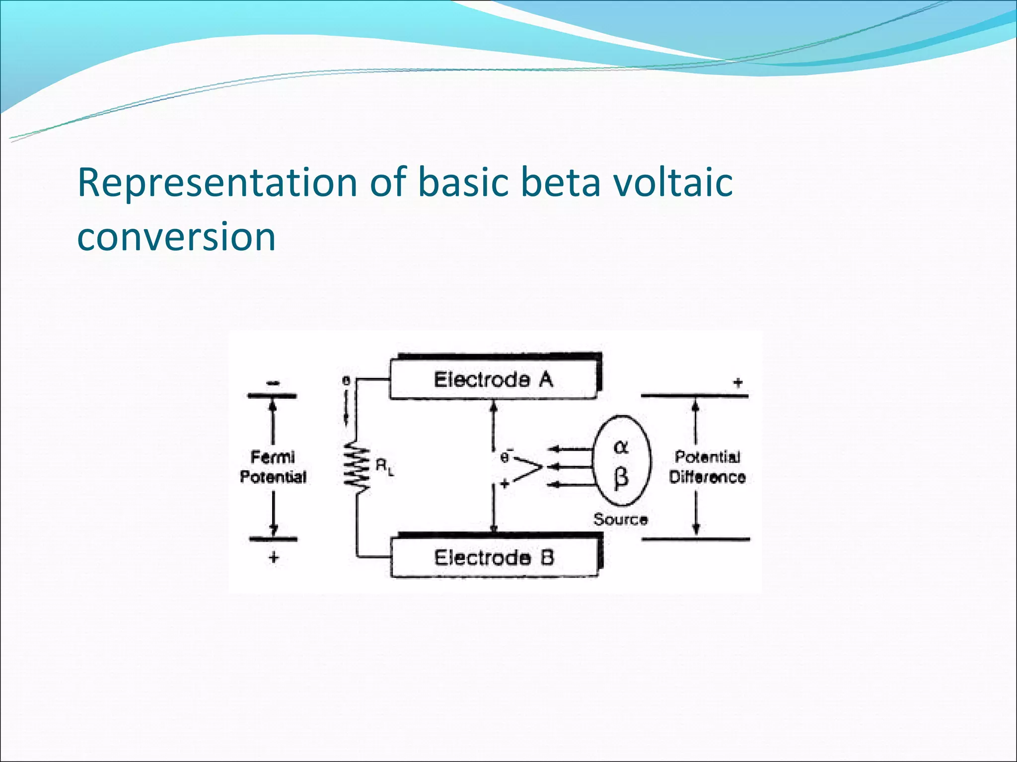


Nuclear batteries offer a compact, lightweight, and self-contained power source that can last for decades without needing replacement like chemical batteries. They generate electricity through the emissions from radioactive isotopes without relying on nuclear reactions, avoiding radioactive waste. Betavoltaics uses the energy from beta particles emitted by a radioactive gas to generate electron-hole pairs in silicon, producing an electric current. Direct charging generators sustain oscillations in an LC circuit through energy absorbed from alpha particles decaying in the circuit's core, delivering excess energy to a load. While nuclear batteries have applications in space, medical devices, mobile electronics, and sensors, their high initial cost and need to meet radiation safety standards must first be addressed.


