Download to read offline
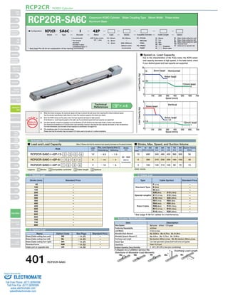
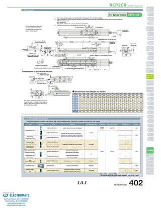

This document provides information on the RCP2CR-SA6C Cleanroom ROBO Cylinder, including: 1) Specifications for the pulse motor-driven actuator such as available speeds and load capacities depending on factors like lead size. 2) Dimensions and other technical details like stroke lengths and compatible controllers. 3) A table showing the actuator's length, mounting hole positions, and weight depending on the stroke size.


