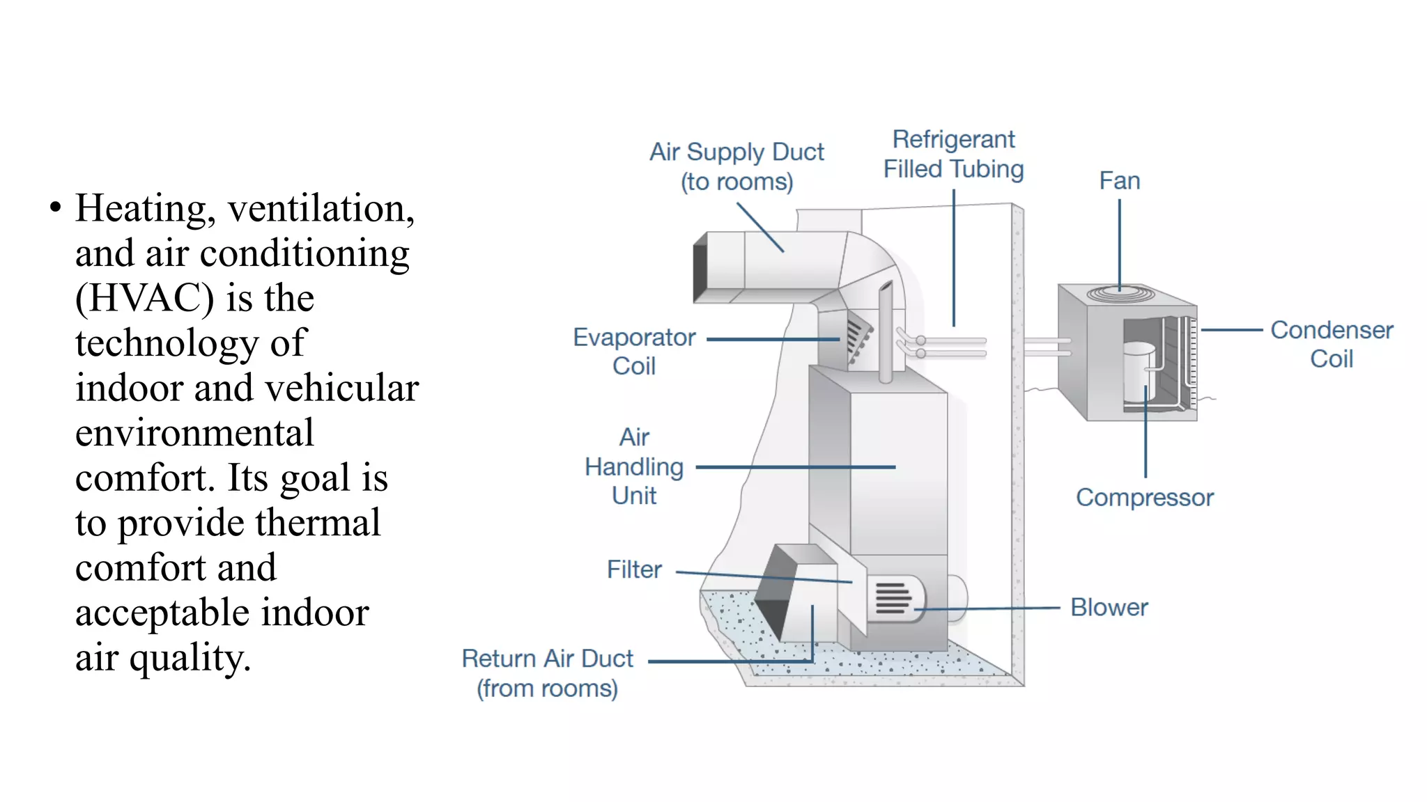
2. • Heating, ventilation,
and air conditioning
(HVAC) is the
technology of
indoor and vehicular
environmental
comfort. Its goal is
to provide thermal
comfort and
acceptable indoor
air quality.
3. COMPONENTS
1. Thermostat. Fixed on easily accessible wall, it may be either programmed in advance or set manually
to keep the home at a desired temperature.
2. Furnace. The furnace is the key component of your HVAC system. It's also the largest, requiring
substantial space -- typically in the cellar, your finished basement, a special closet designed for that
purpose. Its function is to heat a supply of air which is to be distributed to various rooms of your
home via the HVAC. This heating process is accomplished using one of four possible heat sources --
combustion (burning natural gas, oil, coal, or propane), electric resistance, heat pump, or solar energy
collected on site.
3. Heat exchanger. The heat exchanger is found inside your furnace unit's housing. This component
switches on when the furnace is activated by thermostat to produce warmer temperatures in winter.
The heat exchanger pulls in cool air, heats it, and circulates the resulting heated air via your ducts and
out through the vents.
4. 4. Evaporator coil. The evaporator coil has an opposite role to the heat exchanger; it acts to cool the air when your
thermostat is set to lower temperatures in summer. Located in a metal enclosure on the furnace's exterior, to the
top or side, the evaporator coil works similarly to an automobile radiator to produce cool air, which is then
circulated through the ductwork.
5. Condensing unit. The condensing unit is connected to the evaporator coil. This unit is installed by HVAC
contractors on the outside of your home and filled with refrigerant gas. When the refrigerant has been cooled to a
liquid by heat exchange with the exterior air, the condensing unit pumps the liquid to the evaporator coil to be
evaporated into a gas once more.
6. Refrigerant lines. The refrigerant lines carry a refrigerant substance to the condensing unit vaporized in the form
of a gas, and return it to the evaporator coil in liquid form. These "lines" are actually narrow tubes manufactured
from a durable heat- and cold-resistant metal such as copper or aluminum.
7. Ductwork. Ductwork refers to the system of ducts that transports air warmed or cooled by the system to the
various areas of your home. Ducts are commonly made of lightweight aluminum. However, they may also be
manufactured from steel, flexible plastic, polyurethane, fiberglass, or fabric.
8. Vents. The vents are the rectangular outlets which transfer the heated or cooled air from the duct system into the
individual rooms of your home. Made of high- and low-temperature safe metal, the vents are located on or near the
ceiling and are usually fronted with angled slats ("vents"). These vents direct the treated air downward to where
people are using the room. Often they may be manually controlled or even closed, to control the amount of heating
or cooling and the area of the room to which it will be directed.
5. BUILDING BASELINE INFORMATION
• ANALYSIS OF ENERGY CONSUMPTIONS AND BUILDING
OPERATION
• Annual Gas Consumption (m3).
• Average Monthly/Daily Gas Consumption (m3)
• Cost of gas and comments on gas purchase contract.
• Other Fuel Consumption, Oil, Coal
• An estimate of the annual cost of electricity consumed (kWh)
• BUILDING INFORMATION
• Identify the building type, age, construction, square footage, roof construction,
roll-up doors, concrete slab, and wall construction.
• Air tightness etc. Height of office areas, Height of shop areas.
6. • BUILDING HVAC EQUIPMENT LISTING AND ASSESSMENT
• A list and description of all major HVAC equipment from nameplate data and
equipment manuals.
• A visual examination of the HVAC equipment, relying on operating and
maintenance personnel to provide the historic information on the building's
operation.
• Comments on equipment age, condition and maintenance requirements.
• CONTROL SYSTEMS
• Identify the types of control systems installed on all HVAC equipment.
• Identify if a Building Management System (BMS) is installed.
• Review the benefits of applying temperature re-sets, night/holiday setbacks,
start/stop optimization and scheduling.
• Review applicability and benefit of Demand Control Ventilation (DCV).
• Review applicability and benefits of Load Shedding and/or Time-of-day
programming for large loads and loads which can be shifted.
7. • CHILLERS, COOLING TOWERS & PACKAGED A/C UNITS
• Review chiller operation, run-times and efficiencies.
• Review cooling tower operation, run-times and efficiencies.
• Evaluate use of Variable Frequency Drives (VFD) on both chiller motors and
cooling tower fans.
• Review A/C units operation, controls, economizer use and scheduling.
• LIGHTING
• Define how lighting is used
• Identify existing and required lighting levels
• Identify existing lamping
• Review applicability of motion detectors and/or reflectors.
8. • ELECTRICAL DEMAND, POWER FACTOR AND LOAD
FACTOR
• Identify demand charges; quantify peak occurrences and the cost of associated
penalties.
• Identify power factor and any extra charges due to a low power factor.
• Analyze motor load factors and harmonics
• Review rate schedules, time-of-use rates and interruptible rates.
• ADDITIONAL EQUIPMENT
• Identification of any other equipment that would contribute to energy savings
(e.g. solar walls, air curtains, destratification units etc.).
9. • HEAT LOSS/ HEAT GAIN CALCULATIONS
• Measurements of temperature gradients
• List building construction information.
• Calculate heating and cooling inputs.
• VENTILATION BALANCE
• Tabular data of test results identifying all exhausts and ventilation.
• Calculation of air flows.
• Estimate of fan efficiency and total building efficiency.
• Analyses of results, estimate of losses and recommendations
• Review of Economizer applications
• Review of Demand Control Ventilation (DCV) applications
• Variable Frequency Drives
10. • SAFETY ISSUES- Report on obvious safety defects:
• Dangerous levels of CO or CO2
• Other significant Indoor Air Quality (IAQ) issues that are observed.
• Fuel leaks, steam leaks, exposed asbestos insulation
• Potential contamination due to areas of Negative Pressure
11. To Summarize
• Determine if all utility systems with product contact and/or aseptic
processing components have been qualified.
• Determine what routine testing of these systems is conducted and how
often.
• Determine what the microbial action and alert levels are for compressed
gases, HVAC systems, water, and steam.
• Determine what the particulate action and alert levels are for compressed
gases and HVAC.
• Review action and alert limits to determine if they are appropriate.
• Determine if there is a site procedure listing what actions need to be taken if
any of these systems exceed these limits.
• Determine if these procedures for “over limits” are followed.