Download as PDF, PPTX
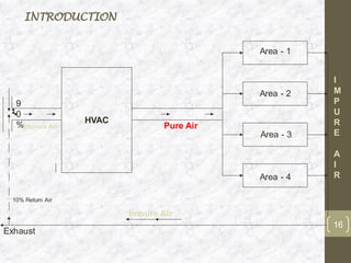
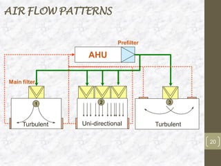
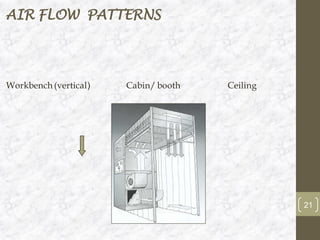
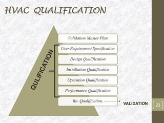

This document discusses the validation of HVAC systems used in the pharmaceutical industry. It begins with introductions to clean rooms, why they are necessary, and how contamination is controlled. It then discusses the components and purpose of HVAC systems, qualification steps including design, installation, and operation qualification, and regulatory requirements. The validation process ensures HVAC systems are designed and functioning properly to maintain environmental controls critical for product quality.