- The document describes a unified power flow controller (UPFC) which consists of two voltage source converters connected respectively in series and shunt with a transmission line, with a common DC link.
- It proposes modeling the UPFC using a discrete simulator in MATLAB with 12-pulse converters to reduce voltage harmonics, and controlling the series and shunt converters separately while coordinating them.
- Simulation results showed the UPFC model reflected static and dynamic characteristics, and harmonics analysis was performed on the output during different system conditions including faults.
![IOSR Journal of Engineering (IOSRJEN) www.iosrjen.org
ISSN (e): 2250-3021, ISSN (p): 2278-8719
Vol. 04, Issue 09 (September. 2014), ||V4|| PP 52-60
International organization of Scientific Research 52 | P a g e
Unified Power Flow Controller: Modeling And Dynamic Characteristic Ho Dac Loc Hochiminh City University of Technology (HUTECH), Hochiminh City Abstract: - Unified power flow controller (UPFC) consists two converters. There are three purposes of this paper, firstly to illustrate the UPFC device based VSC designs, then to describe a decoupling method the UPFC’s controller into two separate control systems of the shunt and the series converters respectively in realizing an appropriate co-ordination between them. Finally, using the Matlab tool to build a discrete simulator for the UPFC with 12 pulse converters. The simulation results show that the developed UPFC model is reflected the static and dynamic characteristics of the UPFC. The harmonics of the output of the model are analyzed. Using the simple power system with UPFC as an example, the dynamics characteristics are studied. The fault status of the system with UPFC is analyzed too. Keyword list: - Times Roman, image area, acronyms, references
I. INTRODUCTION
The developing interest in tools for power flow control in a power system has increased significantly during the last 10 years. Demand for research in this field is motivated by rapid transformations in both technology and organization of the power system industry [1]. The deregulation and competitive environment in the contemporary power networks will imply a new scenario in terms of load and power flows condition and so causing problems of line transmission capacity. For this reason, Flexible AC Transmission System (FACTS) controllers has rapidly developed to meet the need for increasing transmission capacity and controlling power flows through predefined transmission corridors. Especially, the improvements in the field of power electronics have had a major impact on the development of this technology. The devices of new FACTS generation are based on the use of high power electronic components such as GTO (Gate Turn-Off Thyristor) and IGBT (Insulated Gate Bipolar Transistor) which makes them respond quickly to the control requirements. It is called by the FACTS technologies based on Voltage Sourced Converter (VSC) designs. The wider application of FATCS leads to numerous benefits for electrical transmission system infrastructure, including increased capacity at minimum cost; enhanced reliability through proven performance; higher levels of security by means of sophisticated control & protection; and improved system controllability with state-of-the-art technology concepts. Thereby, these FACTS devices are able to act almost instantaneously to changes in power system [2]. The most powerful in family of FACTS devices is the Unified Power Flow Controller (UPFC), because it can control simultaneously all three parameters of transmission power line (line impedance, voltage and phase angle). In practice, the UPFC device consists of two Voltage Source Converters (VSC) connected respectively in shunt and in series with the transmission line, and connected to each other by a common DC link including a storage capacitor. The shunt converter is used for voltage regulation at the point of connection injecting an opportune reactive power flow into the line and to balance the real power flow exchanged between the series converter and the transmission line. The series converter can be used to control the real and reactive line power flow inserting an opportune voltage with controllable magnitude and phase in series with the transmission line. Thereby, the UPFC can perform functions of reactive shunt compensation, active and reactive series compensation and phase shifting [3]. There are many different UPFC models have been investigated by several authors [4-6]. The three main purposes of the paper are firstly to illustrate the UPFC configuration based on VSC’s, and then describe a decoupling method the UPFC’s controller into two separate control systems of the shunt and the series converters respectively in realizing an appropriate co-ordination between them, and finally to simulate a new discrete UPFC model based on 12-pulse VSC using Matlab Power Block/Simulink as simulation program. Besides, PWM method is applied to decrease total of voltage harmonics in simulation output of converters.
II. THE UPFC CONFIGURATION– BASED VOLTAGE SOURCE CONVERTER
1. VSC design concept
The single-line diagram of the UPFC is a combination of two VSC configurations shown in Figures 1. As shown in Figures 1, VSC designs are composed of two basic configurations: A) Shunt Connected VSC System, and](https://image.slidesharecdn.com/h04945260-141016021623-conversion-gate02/85/H04945260-1-320.jpg)
![Unified Power Flow Controller: Modeling And Dynamic Characteristic
International organization of Scientific Research 54 | P a g e
In order to eliminate harmonic content from the output voltage, various techniques can be adopted. A
multiple-pulse arrangement by combining the output of cascade or parallel VSCs can be adopted as a solution
using a multi-winding transformer or inter-phase transformer magnetic. The pulse width modulation (PWM)
technique can be implemented to control harmonic content from the output voltage too. Moreover, harmonic
filters can be also adopted in combination with the above techniques. In this paper PWM control is utilized,
allowing for simplified two winding interconnecting transformer designs.
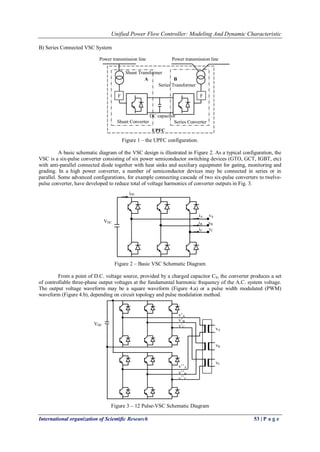
Figure 4 – VSC Output Voltage Waveforms
In the configuration of UPFC, there are two independent VSCs interconnected via coupling capacitor as Shunt
converter and Series converter.
Shunt Connected VSC – the VSC is connected to the power system via a shunt connected transformer. By
varying the amplitude and the phase of the output voltages produced, the active power and the reactive power
exchange between the converter and the A.C. system can be controlled in a manner similar to that of a rotating
synchronous machine. If the amplitude of the output voltage is increased above that of the AC system voltage,
the VSC generates reactive power to the power system. If the amplitude of the output voltage is decreased below
that of the AC system voltage, the VSC absorbs reactive power from the power system.
Series Connected VSC – the VSC is connected to the power system in series via a series connected
transformer. By varying the amplitude and the phase of the output voltages produced, the magnitude and the
angle of the injected voltage can be controlled. The VSC output voltage injected in series with the line acts as an
AC voltage source. The current flowing through the VSC corresponds to the line current. The VA rating of the
VSC is determined by the product of the maximum injected voltage and the maximum line current.
2. Instantaneous power flow delivered by a VSC into a power system
A converter connected to a power system, which is able of power exchange between the power system
and the DC storage capacitor, can be represented by a three symmetrical sinusoidal voltage sources. A
symmetrical three-phase system can be transformed into a synchronously-rotating orthogonal system. A new
coordinate system, having the axes rotating at the synchronous angular speed of the fundamental network
voltage , is defined on the basis of the d-q transformation. In the Fig. 2 the VSC is supplied by a voltage
system vector VS = (VSA, VSB, VSC), with R and L are respectively the transformer equivalent resistances and
inductances. The d-q transformation of the supply voltage system VS is made using the following equations:
1 1 V
V 1 SA
SD 2 2
V
V 3 3 SB SQ 0 V 2 2 SC
(1)
where :
SQ
SD
d
;
dt
V
arct g( )
V
On the basis of this d-q transformation, the instantaneous active and reactive power flowing into the power
system delivered by the VSC [6], neglecting transformer losses and balanced condition; and choose VSD
=VSA, VSQ =0 are :](https://image.slidesharecdn.com/h04945260-141016021623-conversion-gate02/85/H04945260-3-320.jpg)
![Unified Power Flow Controller: Modeling And Dynamic Characteristic
International organization of Scientific Research 56 | P a g e
From [] the output values of controller of Shunt Converter to evaluate the d-q components of equivalent output
voltage source, VSh,D and VSh,Q can be shown as below :
'
Sh
Sh,D lD 1Sh
' '
Sh Sh
Sh,Q lQ 2Sh 2Sh
L
v v y
L L
v v y y
(8)
' Sh
Sh
b
L
L
z
(9)
with assuming that Vl,D = |vl| ; Vl,Q = 0; the LSh = shunt transformer leakage inductance; Zb is the base
impedance. Therefore, the module and displacement angle of equivalent voltage source of shunt converter are
calculated as follows :
2 2
Sh Sh,D Sh,Q
Sh,Q
Sh
Sh,D
V v v
v
arctg
v
(10)
At the same manner, the output variables y1Se , y2Se are used to evaluate the d-q components of series converter
of equivalent voltage source , VSe,D and VSe,Q by following equations :
'
Se
Se,D lD rD 1Se
'
Se
Se,Q lQ rQ 2Se
L
v (v v ) y
L
v (v v ) y
(12)
' 1 Se
Se
b
(L L )
L
z
(13)
2 2
Se Se,D Se,Q
Se,Q
Se
Se,D
V v v
v
arctg
v
(14)
with assuming that Vl,D = |vl| ; Vl,Q = 0; the LSe = shunt transformer leakage inductance, and L1 is the line
inductance. Therefore, the module and displacement angle of equivalent voltage source of shunt converter are
calculated as follows :
2. Converter control technique
On the basic of operation requirements, the scheme of switching the converter’s elements, such as GTO’s or
IGBT’s, may be different. In this paper, as shown above, the PWM switching control technique has been
considered. In this case the three phases of the output converter voltage result:
yA y DC y
0
yB y DC y
0
yB y DC y
1
v m V sin( t )
2
1
v m V sin( t 120 )
2
1
v m V sin( t 240 )
2
(15)
here my , y are the amplitude modulation ratio and phase angle of converter output voltage. These
control variables are the input control signals of converters of UPFC according to PWM switching technique. If
we apply (12) for Shunt converter, then mSh is the index modulation and Sh is the phase displacement angle
with respect to Vl (sending voltage). The same equation to Series converter, mSe is the index modulation and
Se is the phase displacement angle with respect to Vl – Vr (compensation voltage). VDC is the value of voltage
across the storage capacitor.](https://image.slidesharecdn.com/h04945260-141016021623-conversion-gate02/85/H04945260-5-320.jpg)
![Unified Power Flow Controller: Modeling And Dynamic Characteristic
International organization of Scientific Research 57 | P a g e
Moreover the following relations are valid:
2 2
yD yQ
y
DC
yQ
y
yD
v v
m 2 2
V
v
arctg
v
(16)
where vyD and vyQ are calculated by (8) and (11) respectively for the series and the shunt inverter.
In both control schemes the PI controllers is applied with parameters in dependence of converter characteristics,
(RSe, LSe), (RSh, LSh) respectively the equivalent impedance of the series and shunt transformer and (Rline, Lline )
the line equivalent impedance.
3. DC-side control
For normal operation of two VSC’s in an UPFC, the DC voltage across the DC storage capacitor CS must be
kept constant. This implies that the active power exchanged
between the UPFC and the power system is zero at steady state operation:
pSe + pSh = 0 (17)
that is, the active power delivered by the shunt inverter pSh is equal to the active power exchange between the
series inverter and the transmission line, pSe. Hence, a DC voltage control system must be realized to keep Vdc
constant by taking the actual value of vdc as the feedback signal against a dc reference signal V*dc []. Moreover,
assuming negligible the losses of the shunt and series converters and coupling transformers the actual value of
the DC capacitor voltage is computed as :
DC Se Sh
DC DC
dv p p
dt C v
(18)
IV. SIMULATION AND RESULTS
All the simulations were made using Matlab Power System Blockset and Simulink. The simulation
results of the discrete UPFC model based 12 pulse-converter are the subject of this section. These results are
obtained based on discrete modulation functions. A simple configuration of power system is applied to validate
the new UPFC model based 12 pulse- converter. The test power system operates at 230 kV and is shown in
Fig.5. The generator is assumed to be an ideal voltage source behind an equivalent Thevenin impedance. The
UPFC model is located at the sending end of the transmission line and is controlled in such a way to follow the
changes in reference values of the line active and reactive power. The Shunt converter and Series converter are
based on 12 pulse-converter with two level ignition signals. Besides, PWM technique with 1080 Hz carrier
frequency, which is modeled by the discrete PWM pulse generator, is used to generate output voltage pulses of
converters. This technique is very suitable for pulse control of UPFC and reduce total harmonic distortion of
output voltage and line current. In those devices, input control variables of converter, such as amplitude
modulation ratio and phase angle are output variables of close-loop power flow controller and close-loop DC
voltage controller.
Fig.5 – Simple test system with UPFC.
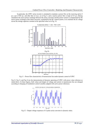
The Fig.8 displays DC voltage of UPFC. The real signal shape of DC voltage in discrete simulation is
an oscillation curve around reference value according to pulses of PWM converter. In Fig.9 output voltage of
Series converter is shown. It is a combination of two 6 pulse converters connected cascade together in which
whole output voltage gains a better result of low harmonic content. This has a very important meaning in
practice,….
In Fig.7, line current though UPFC is shown by discrete type.
UPFC Sys
P, Q
Transmission line
VS VR
VIdeal
ILine](https://image.slidesharecdn.com/h04945260-141016021623-conversion-gate02/85/H04945260-6-320.jpg)
![Unified Power Flow Controller: Modeling And Dynamic Characteristic
International organization of Scientific Research 60 | P a g e
0.06 0.07 0.08 0.09 0.1 0.11 0.12 0.13 0.14 0.15
-1.5
-1
-0.5
0
0.5
1
1.5
VOLTAGE OF UPFC BUS IN DYNAMIC STATES
TIME (Sec.)
VOLTAGE (pu)
Fig.13 – Voltage characteristic of transmission line under dynamic control of UPFC
0.06 0.07 0.08 0.09 0.1 0.11 0.12 0.13 0.14 0.15
-5
-4
-3
-2
-1
0
1
2
3
4
5
LINE CURRENT OF UPFC BUS
TIME (sec.)
CURRENT (pu)
Fig.14 – Current characteristic of transmission line under dynamic control of UPFC
V. CONCLUSIONS
This paper after a brief summary of the UPFC configuration based converter, illustrates in detail the
control system model of UPFC with two separate control systems for the series and shunt inverters and a control
for their coordination. Finally, a discrete simulation of new UPFC model based 12 pulse converter using
Matlab/Simulink as simulation program is shown and some simulation results are illustrated to validate the
implemented this UPFC model. Especially, the simulation results have provided the practical operating
processes of UPFC and converter. These give us the practical views of action of every part of devices and
responses of power system under UPFC working. The results are obtained for a PWM-based control
technique, but it's very simple to modify the converter control technique such as phase control.
However, this new discrete UPFC model based on 12 pulse converter seems not to be suitable for application in
contingency analysis because it is quite complex in separating control systems of Shunt converter and series
converter properly with maintained control quality A UPFC with matrix converter is useful only for steady
operation modes.
This new discrete 12 pulse converter model will be modified to be able to perform a damping oscillation
operating functions in such a way in the future researches.
REFERENCES
[1] L. Gyugyi, C.D. Shauder, S.L. Williams, T.R. Rietman, D.R. Torgerson, A. Edris. “The unified power
flow controller: A new approach to power transmission control”, IEEE Trans. On Power Delivery,
Vol.10, No.2, April 1995, pp.1085-1097.
[2] H.Fujita, Y. Watanabe, H.Akagi. “Control and analysis of a unified power flow controller”. IEEE Trans.
On Power Electronics, Vol.14, No.6, Nov. 1999.](https://image.slidesharecdn.com/h04945260-141016021623-conversion-gate02/85/H04945260-9-320.jpg)