The document provides operating instructions for the Humboldt Nuclear Density Moisture Gauge (HS 5001 EZ), which uses gamma radiation and neutron thermalization to measure the density and moisture content of construction materials. It describes the standardization, site preparation, and testing procedures for soils, asphalt, and thin layers. Key steps include standardizing the gauge daily using a reference block, preparing a level surface and hole for testing, inputting reference values into the gauge, and taking measurements using different time settings based on the material and test method.
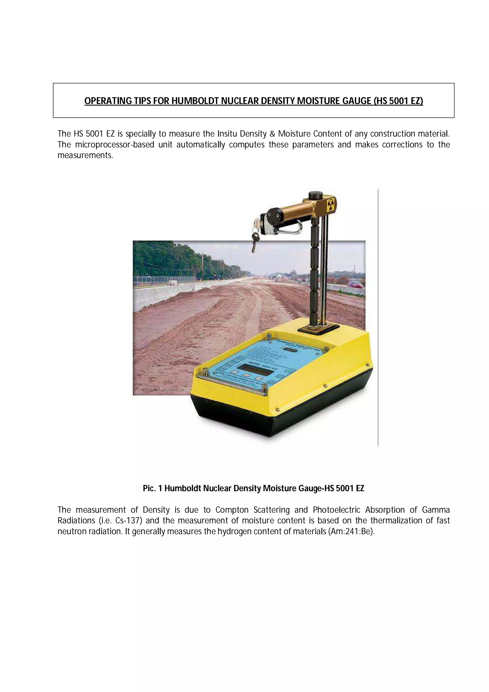


![arc_welding_safety[1]](https://cdn.slidesharecdn.com/ss_thumbnails/5ec67737-dec9-46f8-8fd9-fb83767a83f8-150902111301-lva1-app6891-thumbnail.jpg?width=640&height=640&fit=bounds)


