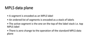
Download as PDF, PPTX
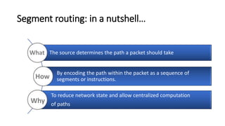

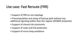

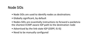


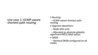
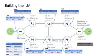
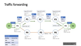

Segment routing allows a node to steer a packet through an ordered list of segments encoded in the packet header. Segments represent instructions like forwarding through specific nodes or along certain paths. By encoding the path in packets, segment routing can compute paths centrally and reduce network state.


![MPLS L3 VPN Tutorial, by Nurul Islam Roman [APNIC 38]](https://cdn.slidesharecdn.com/ss_thumbnails/mplsl3vpnapnic381410820509-140915192004-phpapp02-thumbnail.jpg?width=640&height=640&fit=bounds)


![Automating ISP Networks Using Ansible and IPAM as a Source of Truth [SoT]](https://cdn.slidesharecdn.com/ss_thumbnails/automatingispnetworksusingansibleandipamasasourceoftruthsot-v25-1-251124105117-d7d4ca24-thumbnail.jpg?width=640&height=640&fit=bounds)


