Download as PDF, PPTX

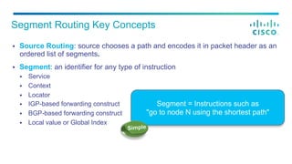
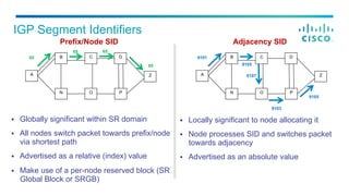
![§ Prefix SID
§ SID encoded as an index
§ Index represents an offset from SRGB base
§ Index globally unique
§ SRGB may vary across LSRs
§ SRGB (base and range) advertised with router
capabilities
§ Adjacency SID
§ SID encoded as absolute (i.e. not indexed)
value
§ Locally significant
§ Automatically allocated for each adjacency
SID Encoding
SRGB = [ 16000 - 23999 ]. Advertised as base = 16,000, range = 7999
Prefix SID = 16041. Advertised as Prefix SID Index = 41
Adjacency SID = 24000. Advertised as Adjacency SID = 24000
SR-enabled Node](https://image.slidesharecdn.com/ts-sp-03-ialvarez-saalvare-cct2015-sr-lab-v4-150520182614-lva1-app6892/85/Segment-Routing-Lab-7-320.jpg)
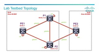
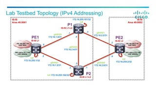
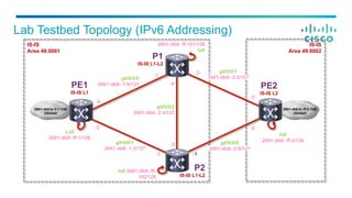


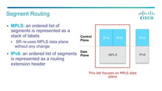
The document provides housekeeping notes for a Cisco Connect session, covering segment routing key concepts and details about the lab setup involving MPLS and IPv6 addressing. It explains how segment identifiers (SIDs) function within the context of both control and forwarding operations and includes specifics on lab testbed topology and instructions for participants. Additionally, it encourages session feedback and introduces Cisco dCloud as a resource for accessing labs and demos.


![MPLS L3 VPN Tutorial, by Nurul Islam Roman [APNIC 38]](https://cdn.slidesharecdn.com/ss_thumbnails/mplsl3vpnapnic381410820509-140915192004-phpapp02-thumbnail.jpg?width=640&height=640&fit=bounds)