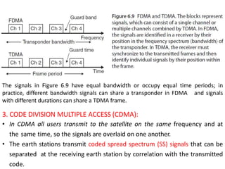
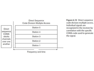
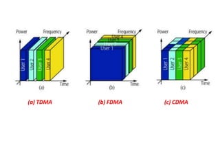
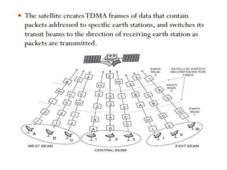
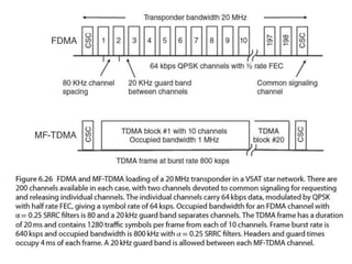
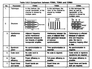
3. • The ability of a satellite to carry many signals at the same time
is known as multiple access.
• Multiple access allows the communication capacity of the
satellite to be shared among a large number of earth stations.
• The basic form of multiple access employed by most
communications satellites is the use of many transponders.
• The signals that earth stations transmit to a satellite may
differ widely in their character – video, data, voice – but they
can be sent through the same satellite using multiple access
and multiplexing techniques.
3.1. Multiple Access: Introduction
4. • Multiplexing is the process of combining a number of signals
into a single signal, so that it can be processed by a single
amplifier or transmitted over a single radio channel.
• Multiplexing can be done at baseband or at an IF.
• The corresponding technique that recovers the individual
signal is called demultiplexing.
• Multiplexing is a key feature of all commercial long distance
communication systems, and is part of the multiple access
capability of all satellite communications systems.
5. • The multiple access technique will influence the capacity and
flexibility of the satellite communication system, its cost, and
its ability to earn revenue.
• The basic problem in any multiple access system is how to
permit a changing group of earth stations to share a satellite
in such a way that satellite communication capacity is
maximized, bandwidth is used efficiently, flexibility is
maintained, and cost to the user is minimized while revenue
to the operator is maximized.
6. There are three basic multiple access techniques.
1. FREQUENCY DIVISION MULTIPLE ACCESS(FDMA):
• In FDMA all users share the satellite at the same time, but
each uplink earth station transmits at a unique allocated
frequency.
• FDMA can be used with analog or digital signals.
2. TIME DIVISION MULTIPLE ACCESS (TDMA):
• In TDMA each user is allocated a unique time slot at the satellite
so that signals pass through the transponder sequentially.
Because TDM causes delays in transmission, it is used only with
digital signals.
7. The signals in Figure 6.9 have equal bandwidth or occupy equal time periods; in
practice, different bandwidth signals can share a transponder in FDMA and signals
with different durations can share a TDMA frame.
3. CODE DIVISION MULTIPLE ACCESS (CDMA):
• In CDMA all users transmit to the satellite on the same frequency and at
the same time, so the signals are overlaid on one another.
• The earth stations transmit coded spread spectrum (SS) signals that can be
separated at the receiving earth station by correlation with the transmitted
code.
10. • An earth station can use Time division multiplexing (TDM) to create
a high-speed digital data stream from many digital channels
delivered to that earth station, and then modulate the data stream
onto an RF carrier and transmit the carrier to the satellite.
• At the satellite, the carrier can share a transponder using TDMA or
FDMA with other carriers from earth stations anywhere within the
satellite’s coverage zone.
• The resulting signal is called TDM-TDMA or TDM-FDMA.
• Note :The distinction between TDM and TDMA: signals at one
earth station are combined by multiplexing (TDM), and then share a
satellite transponder with signals from other earth stations by
multiple access (TDMA or FDMA).
11. • In all three of the classical multiple access techniques, some
resource is shared.
• If the proportion allocated to each earth station is fixed in
advance, the system is called Fixed Access (FA) or Preassigned
Access (PA).
• If the resource is allocated as needed depending on changing traffic
conditions, the multiple access technique is called Demand
assignment multiple access (DAMA).
• Demand assignment blurs some of the distinctions between FDMA
and TDMA.
• Since stations in a FDMA-DAMA system transmit only when they
have traffic.Demand assignments with FDMA is sometimes used in
very small aperture terminal (VSAT) systems, where earth stations
may have traffic to send only intermittently. Fixed assignment is
wasteful of transponder capacity, so demand assignment is used.
12. • Similarly, a group of earth stations may access part of the
bandwidth of a transponder using TDMA, while other TDMA
groups of earth stations share different sections of the
transponder bandwidth.
• This approach has been used in both VSAT and mobile satellite
systems.
• Demand assignment can also be used with CDMA to reduce the
number
of signals in the transponder at any one time.
• Systems that combine both FDMA and TDMA techniques are
sometimes called Hybrid Multiple Access Schemes or Multi-
frequency Time Division Multiple Access (MF-TDMA).
13. 3.2. Frequency Division Multiple Access (FDMA)
• FDMA was the first multiple access technique used in satellite
communication systems.
• When satellite communications began in the 1960s, most of the
traffic carried by satellites was telephony.
• All signals were analog, and analog multiplexing was used at earth
stations to combine large numbers of telephone channels into a
single baseband signal that could be modulated onto a single RF
carrier.
• Available frequency band is divided into N non-overlapping
channels.
• Guard band minimize interference between channels.
14. • Early satellite systems used FDM to multiplex up to 1800 telephone
channels into a wide baseband occupying up to 8MHz, which was
modulated onto an RF carrier using FM.
• The FDM-FM RF carrier was transmitted to the satellite, where it
shared a transponder with other carriers using FDMA.
• The technique is known as FDM-FM-FDMA, and was the preferred
method for the transmission of telephone channels over INTELSAT
satellites for more than 20 years.
15.
16. • Figure 6.11 shows a transponder operating with FDMA.
• Three transmitting earth stations send signals at different uplink
frequencies to a single transponder on a GEO satellite.
• The transponder amplifies the received signals and retransmits
them on the downlink at frequencies f1, f2, and f3.
• All earth stations within the satellite’s coverage zone receive all
three signals.
• The three receivers shown in Figure 6.11 could be at one earth
station or at three separate earth stations.
• In either case, BPFs centered at the frequencies f1, f2, and f3
are used to select the wanted transmission from within the
bandwidth of the transponder.
• The BPFs are usually in the intermediate (IF) section of the receiver
to simplify their design.
17.
18. • Figure 6.12 shows a typical fixed assignment FDMA plan for two
C-band transponders.
• The triangles represent RF carriers with the transmitting earth
station country and RF bandwidth shown inside the triangle.
• The signals could be video, data, or voice.
• Frequencies shown are for the downlink from the satellite.
• The triangles represent the location of each signal within an
allocated bandwidth such as that of a transponder .
19. Example: Transponder #1 in Figure 6.12 receives three signals from
different uplink earth stations; in this example, two are in the United
Sates and one is in Chile.
• Each of the signals has a bandwidth of 10MHz.
• The uplink signals from the two earth stations in the United
States are transmitted on carrier frequencies of 5939 and
5951MHz.
• The uplink signal from the earth station in Chile is transmitted
with a carrier frequency of 5963MHz.
• The transponder down converts each received signal by 2225MHz
giving the downlink carrier frequencies of 3714, 3726, and
3738MHz.
• All earth stations within the antenna beam connected to
transponder #1 can receive all of the signals transmitted by the
transponder.
• Each receiving earth station can extract any signals that are
destined for that particular earth station.
20. • Transponder #2 in Figure 6.12 receives two signals with different
bandwidths.
• The 20MHz wide signal originates from an earth station in the
United States at a carrier frequency of 5984MHz.
• The 10MHz bandwidth signal originates from an earth station in
Chile at a carrier frequency of 5996MHz.
• Transponder #2 down converts these signals by 2225MHz and
transmits them at carrier frequencies of 3759 and 3771MHz.
• Both of these signals can be received by the same earth
stations that receive signals from transponder #1.
• Typically, large C-band earth station receivers have front ends
with a bandwidth of 500 or 1000MHz to allow reception of all C-
band carriers
21. • The use of microwave filters to separate transponders makes the
fixed assignment approach to FDMA very inflexible.
• Changing the frequency assignment or bandwidth of any one
transmitting earth station requires retuning of the filters at
several receiving earth stations.
• The fixed assignment FDM-FM-FDMA scheme illustrated in Figure
6.12 also makes inefficient use of transponder bandwidth and
satellite capacity.
FDMA Receiver:
• Every earth station that operates in a FDMA network must have a
separate IF receiver.
• SCPC systems can have a very large number of carriers in
one transponder.
22. NOTE: In signal processing, a root-raised-cosine filter (RRC), sometimes known as
square-root-raised- cosine filter (SRRC), is frequently used as the transmit and
receive filter in a digital communication system to perform matched filtering.
This helps in minimizing Intersymbol Interference (ISI). The combined response
of two such filters is that of the raised-cosine filter. It obtains its name from the
fact that its frequency response is the square root of the frequency response of
the raised-cosine filter.
23. • Figure 6.13 shows how the IF bandwidth of a receiving earth
station could be configured to receive 25 digital data channels.
• Each with an occupied bandwidth of 1.94MHz from a 54MHz
wide Ku-band transponder.
• The IF band is centered at 70MHz requiring the BPFs that
extract the individual signals.
• The 200 kHz frequency spaces between the channels are
called guard bands.
• Guard bands are essential in FDMA systems to allow the
filters in the receiver to select individual channels.
24.
25.
26. • When an earth station sends one signal on a carrier, the FDMA
access technique is called single channel per carrier (SCPC).
• Thus a system in which a large number of small earth stations, such
as mobile telephones, that access a single transponder using
FDMA is called a Single Channel Per Carrier Frequency Division
Multiple Access (SCPC-FDMA) system.
• Hybrid multiple access schemes can use TDM of baseband
channels, which are then modulated onto a single carrier.
• A number of earth stations can share a transponder using FDMA,
giving a system known as TDM-SCPC-FDMA.
• TDM-SCPC-FDMA is often used by VSAT networks in which the
earth stations transmit many digital signals.
27. FDMA DISADVANTAGES:
1. The presence of guard bands.
2. Requires right RF filtering interference to minimize
adjacent channel.
3. Most satellite transponders use HPAs, which are driven
close to saturation, causing non-linear operation.
• A transponder using a Traveling Wave Tube Amplifier (TWTA)
is more prone to non-linearity than one with a Solid State
High Power Amplifier (SSHPA).
• Non-linearity of the transponder HPA causes a reduction in
the overall (CNR)o at the receiving earth station when FDMA
is used because intermodulation (IM) products are generated
in the transponder.
28. • Intermodulation (IM) products are generated whenever
more than one signal is carried by a non-linear device.
• Sometimes filtering can be used to remove the IM
products, but if they are within the bandwidth of the
transponder they cannot be filtered out.
29. Calculation of CNR With Intermodulation:
• Intermodulation between carriers in a non-linear transponder
adds unwanted products into the transponder bandwidth that
are treated as though the interference were Gaussian noise.
• The output backoff (the level of a signal at the o/p of an
amplifier relative to the maximum possible o/p level. Ex.:
Max. o/p level is +40dB and measured o/p level is +34dB,
then OPBO is 6dB) of a transponder reduces the output
power level of all carriers, which therefore reduces the CNR in
the transponder.
• The transponder CNR appears as (CNR)up in the calculation of
the overall (CNR)o in the earth station receiver.
32. • In TDMA a number of earth stations take turns transmitting
bursts (large amount of data transmitting in short time) of RF
signal through a transponder.
• The bit rate of a burst is determined by the bandwidth of the
RF signals and the modulation.
• The RF bandwidth can be equal to the full transponder
bandwidth that typically will create a high bit rate.
• Since all practical TDMA systems are digital, TDMA has all
the advantages over FDMA that digital signals have over
analog.
• In TDMA systems, because the signals are digital and can be
divided by time, are easily reconfigured for changing traffic
demands, are resistant to noise and interference, and can
readily handle mixed video, data, and voice traffic.
3.3. Time Division Multiple Access (TDMA)
33. • One major advantage of TDMA when using the entire
bandwidth of a transponder is that only one signal is
present in the transponder at one time, thus overcoming
some of the problems caused by non-linear transponders
operating with FDMA.
• However, using all of the transponder bandwidth requires
every earth station to transmit at a high bit rate, which
requires high transmitter power.
• Hence TDMA is not well suited to narrowband signals from
small earth stations.
• TDMA can be used to assemble multiple bit streams into a
single higher speed digital signal that has an RF bandwidth
much less than the transponder bandwidth.
34. • Several such MF-TDMA (Multi-Frequency TDMA) signals
can share a transponder using FDMA.
• MF-TDMA is well suited to internet access systems
using GEO and LEO satellites, and systems with satellite
telephones and mobile video links.
TDMA for Fixed Networks of Earth Stations:
• TDMA is an RF multiple access technique that allows a
single transponder to be shared in time between RF
carriers from different earth stations.
• In a TDMA system, the RF carrier from each earth station
sharing a transponder is sent as a burst at a specific time.
• At the satellite, bursts from different earth stations arrive
sequentially, so the transponder carries a continuous
signal made up of a sequence of short bursts coming
from different earth stations.
35. • The burst transmission is assembled at a transmitting
earth station so that it will correctly fit into the TDMA
frame at the satellite.
• The frame typically has a length between 125 μs and
20ms, and the burst from the earth station must be
transmitted at the correct time to arrive at the satellite in
the correct position within the TDMA frame.
• This requires synchronization of all the earth stations in a
TDMA network, adding considerable complexity to the
equipment at the transmitting station compared to FDMA.
• Each station must know exactly when to transmit, typically
within one or 2 ÎĽs, so that the RF bursts arriving at the
satellite from different earth stations do not overlap.
• A time overlap of two RF signals is called a collision and
results in data in both signals being lost. Collisions must
not be allowed to occur in a TDMA system.
36.
37. • A receiving earth station must synchronize its receiver to each
of the sequential bursts in the TDMA signal and recover the
transmission from each uplink earth station.
• The transmissions are then broken down to extract the data
bits, which are stored and reassembled into their original bit
streams.
• The individual transmissions from different uplink earth
stations are usually sent using QPSK or higher order
modulation, and may have small differences in carrier and
clock frequencies, and different carrier phases.
• A bit is the fundamental unit in digital transmission. Data are
generated by terminals (e.g., a personal computer) as bits, or
by conversion of an analog speech or video signal to digital
form as a serial bit stream.
• The state of the RF carrier is called a symbol, and the symbol
rate is in units of bauds, or symbols per second.
38. TDMA Frame Structure:
• A TDMA frame contains the signals transmitted by all of the earth
stations in a TDMA network, or all of the earth stations in one MF-
TDMA group.
• A frame typically has a fixed length, and is built up from the burst
transmissions of each earth station, with guard times between
each burst.
39. Goals in TDMA:
1. Each earth station must be able to extract the data
bits and other information from burst transmissions of
other earth stations in the TDMA network.
2. The transmitted bursts must contain synchronization
and identification information that help receiving earth
stations to extract the traffic portions of the frame
without error.
These goals were achieved by dividing TDMA burst
transmissions into two parts:
1. PREAMBLE OR HEADER that contains a
synchronization waveform, identification bits, and
control bits.
2. A traffic portion containing data bits.
40. Synchronization of a TDMA :
• Synchronization of a TDMA receiver is achieved with the
portion of the frame that contains carrier and bit clock
synchronization waveforms.
• In some systems, a separate reference burst may be
transmitted by one of the stations, designated as the master
station.
• A reference burst is a preamble followed by no traffic bits.
• The control bits in a preamble contain information for each
earth station in the network to assist the station in timing its
transmissions correctly.
• Traffic bits are the revenue producing portion of each frame.
• The preamble and reference bursts represent overhead.
• The smaller the overhead, the more efficient the TDMA system.
41.
42. • Early TDMA systems were designed around 125 μs frames.
• Figure 6.22 shows a generic TDMA burst from one earth
station. All bursts start with a preamble or header.
• In Figure CBTR stands for Carrier And Bit Timing Recovery,
often 176 symbols in duration, formed of a period of
unmodulated carrier to synchronize the locally generated
carrier that drives the demodulator in the receiver, and a
sequence of modulated symbols that are used to
synchronize the receiver bit clock.
• The next symbols in the burst are a UNIQUE WORD (UW),
typically 16–64 bits that are used to identify the
transmitting earth station and to determine whether the
demodulator locked up correctly.
• A transmitting station identifier (address) may be added if
all transmitting stations use the same unique word.
43. • The next block in the burst is for CONTROl, marked
CNTL in Figure 6.22, and can take many forms.
• Information in the control block includes instructions for the
receiver such as the modulation and FEC applied to the
preamble and traffic segments, the length of the traffic
burst, and warnings of any changes that will occur in the
next frame.
• There may be a FORWARD ERROR CORRECTION (FEC)
segment at the end of the preamble that can be used by
both the transmitting and receiving stations to ascertain
whether the preamble was received correctly.
• Errors in the preamble can result in the traffic section of
the burst being corrupted, requiring a retransmission of the
entire frame
44.
45.
46.
47. 3.4. Demand Assignment Multiple Access (DAMA)
• Demand assignment can be used in any satellite
communication link where traffic from an earth station is
irregular.
• An example is a LEO satellite system providing links to
mobile telephones.
• Demand assignment allows a satellite channel to be
allocated to a user on demand, rather than continuously,
which greatly increases the number of simultaneous
users who can be served by the system.
• Most SCPC-FDMA systems use demand assignment to
ensure that the available bandwidth in a transponder is
used as fully as possible.
48. • Demand assignment systems require two different types of
channel: a common signaling channel (CSC) and a
communication channel.
• A user wishing to enter the communication network first calls
the controlling earth station using the CSC, and the
controller then allocates a pair of channels to that user.
• The CSC is usually operated in random access mode
because the demand for use of the CSC is relatively low,
messages are short, and the CSC is therefore lightly loaded.
The CSCs are located at the ends of the transponder
occupied bandwidth.
• The control packet is received by the gateway earth station
and decoded. The control packet contains the address of the
station requesting the connection, any other relevant data.
• Bent pipe transponders are often used in demand
assignment mode, allowing any configuration of FDMA of
MF-TDMA channels to be adopted.
49.
50. 3.5. Random Access (RA)
• Random access is a widely used satellite multiple
access technique where the traffic density from
individual users is low.
• For example, VSAT terminals and satellite mobile
telephones often require communication capacity
infrequently.
• These users can share transponder space without any
central control or allocation of time or frequency,
provided the average activity level is sufficiently low.
51. • In a true random access network, a user transmits
packets whenever they are available.
• The packet has a destination address, and a source
address.
• All stations receive the packet and the station with the
correct address stores the data contained in the packet
and sends an acknowledgement back to the
transmitting station.
• All other stations ignore the packet, unless it is
designated as a broadcast packet with information for
all stations, in which case no acknowledgment is sent.
52. • In satellite communication systems, the network is more
usually a star configuration with a single gateway and many
small earth stations or portable terminals.
• Inbound packets are received by the gateway earth station
and forwarded to their destinations.
• Early work on random access techniques for radio channels
was done at the University of Hawaii, led by Norman
Abramson where the system was called ALOHA and was
known by the generic term PACKET RADIO.
• As more transmitters attempt to share the same transponder,
collision between packets will occur.
53.
54.
55. • Transmitting stations either monitor their own
transmissions and can determine when a transmitted
packet has been corrupted by a collision, or wait to
receive an acknowledgement from the receiving station.
• If no acknowledgement arrives within a set time, a repeat
transmission of the packet is made.
• A retransmission of the corrupted packet is required
whenever a collision is detected; the transmitter waits for a
random time and then retransmits the packet.
• Efficiency of the random access system can be improved
to 36% using slotted Aloha if transmitters are allowed to
transmit only in specific time slots so that partial collisions
do not occur.
56. 3.6. Code Division Multiple Access (CDMA)
• CDMA is a system in which a number of users can
occupy all of the transponder bandwidth all of the time.
• CDMA signals are encoded such that information from
an individual transmitter can be recovered by a receiving
station that knows the code being used.
• Each transmitting station is allocated a CDMA code; any
receiving station that wants to receive data from that
earth station must use the correct code.
• CDMA codes are typically 16 bits to many thousands of
bits in length, and the bits of a CDMA code are called
chips to distinguish them from the message bits of a
data transmission.
57. • The data bits of the original message modulate the
CDMA chip sequence, and the chip rate is always
much greater than the data rate.
• This greatly increases the speed of the digital
transmission, widening its spectrum in proportion to the
length of the chip sequence. As a result, CDMA is also
known as spread spectrum.
• Direct sequence spread spectrum (DSSS) is the only
type currently used in civilian satellite communication;
• Frequency hopping spread spectrum (FH-SS) is used
in the Bluetooth system for multiple access in short
range local area wireless networks.
58. • CDMA was originally developed for military
communication systems, where its purpose was to
spread the energy of a data transmission across a wide
bandwidth to make detection of the signal more difficult.
• CDMA has become popular in cellular telephone
systems where it is used to enhance cell capacity.
• However, it has not been widely adopted by satellite
communication systems because it usually proves to be
less efficient, in terms of capacity, than FDMA and
TDMA.
• The GPS navigation system uses DSSS CDMA for the
transmission of signals that permit precise location of a
receiver in three dimensions.