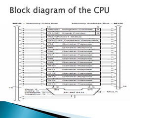
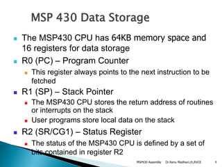
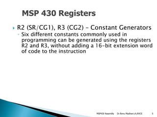
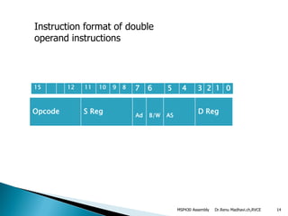
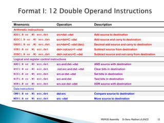
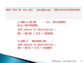
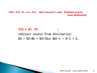
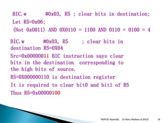
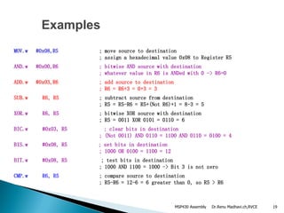
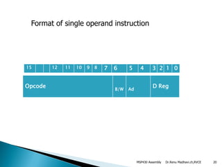
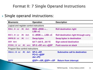
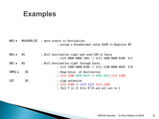
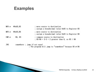
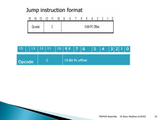
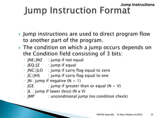
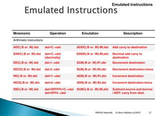
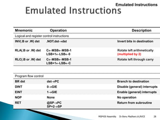
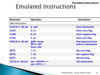
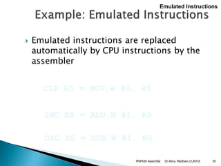
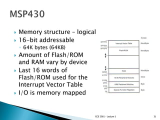
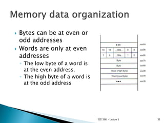
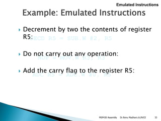
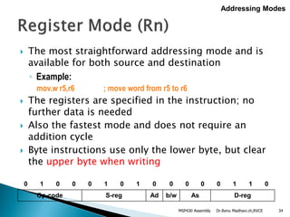
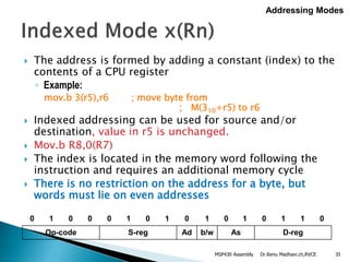
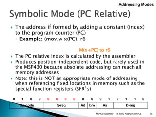
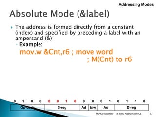
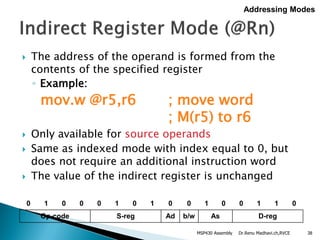
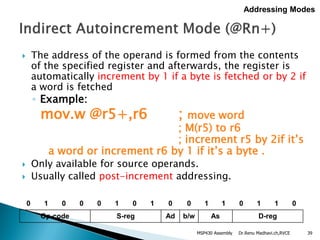
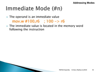
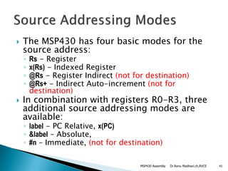
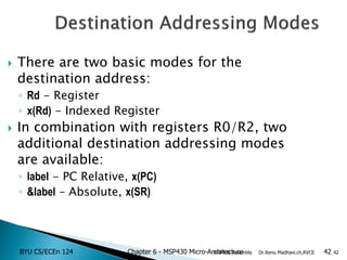
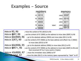
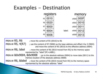
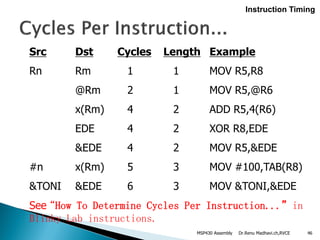
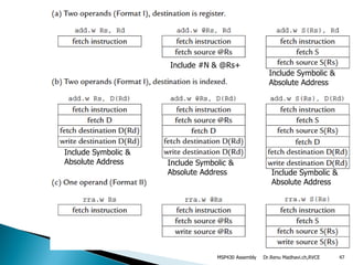
By
Dr.CH.Renu Madhavi
Associate Professor
E&IE Department
RVCE
1Dr.Renu Madhavi.ch,RVCEMSP430 Assembly
Topics to Cover
 MSP 430 Data Storage
 Double Operand Instructions
 Single Operand Instructions
 Jump Instructions
 Emulated Instructions
 Example Assembly Program
2Dr.Renu Madhavi.ch,RVCEMSP430 Assembly
Dr.Renu Madhavi.ch,RVCE 4
MSP 430 Data Storage
 The MSP430 CPU has 64KB memory space and
16 registers for data storage
 R0 (PC) – Program Counter
 This register always points to the next instruction to be
fetched
 R1 (SP) – Stack Pointer
 The MSP430 CPU stores the return address of routines
or interrupts on the stack
 User programs store local data on the stack
 R2 (SR/CG1) – Status Register
 The status of the MSP430 CPU is defined by a set of
bits contained in register R2
MSP430 Assembly
Dr.Renu Madhavi.ch,RVCE 5
 R2 (SR/CG1), R3 (CG2) – Constant Generators
◦ Six different constants commonly used in
programming can be generated using the registers
R2 and R3, without adding a 16-bit extension word
of code to the instruction
MSP 430 Registers
MSP430 Assembly
Dr.Renu Madhavi.ch,RVCEMSP430 Assembly 6
Reg As constant
R2 10 0004h
R2 11 0008h
R3 00 0000h
R3 01 0001h
R3 10 0002h
R3 11 0FFFFh
Dr.Renu Madhavi.ch,RVCEMSP430 Assembly 7
:
 No special instructions required
 No additional code word for the six constants
 No code memory access required to retrieve
the constant
Dr.Renu Madhavi.ch,RVCEMSP430 Assembly 8
Dr.Renu Madhavi.ch,RVCE 9
 R4-R15 – General Purpose registers
◦ The general purpose registers R4 to R15 can be
used as data registers, data pointers and indices.
◦ They can be accessed either as a byte or as a
word
◦ Instruction formats support byte or word
accesses
◦ The status bits of the CPU in the SR are updated
after the execution of a register instruction.
MSP430 Assembly
 Note: The data in the register can be
accessed using word or byte instructions. If
byte instructions are used, the high byte is
always 0 in the result. The status bits are
handled according to the result of the byte
instruction.
Dr.Renu Madhavi.ch,RVCEMSP430 Assembly 10
 The complete MSP430 instruction set consists
of 27 core instructions and 24 emulated
instructions
 The emulated instructions do not have op-
codes themselves, instead they are replaced
automatically by the assembler with an
equivalent core instruction.
Dr.Renu Madhavi.ch,RVCEMSP430 Assembly 11
 Double Operand Instructions(12)
 Single Operand Instructions(7)
 Jump Instructions(8)
Dr.Renu Madhavi.ch,RVCEMSP430 Assembly 12
Dr.Renu Madhavi.ch,RVCE 13
 Double operand Instructions include
 1.Arthimatic Instructions
 2.Logical Instructions
 3.Data instructions
MSP430 Assembly
Dr.Renu Madhavi.ch,RVCEMSP430 Assembly 14
Instruction format of double
operand instructions
Opcode S Reg Ad B/W AS
D Reg
15 12 11 10 9 8 7 6 5 4 3 2 1 0
Dr.Renu Madhavi.ch,RVCE 15
Mnemonic Operation Description
Arithmetic instructions
ADD(.B or .W) src,dst src+dstdst Add source to destination
ADDC(.B or .W) src,dst src+dst+Cdst Add source and carry to destination
DADD(.B or .W) src,dst src+dst+Cdst (dec) Decimal add source and carry to destination
SUB(.B or .W) src,dst dst+.not.src+1dst Subtract source from destination
SUBC(.B or .W) src,dst dst+.not.src+Cdst Subtract source and not carry from destination
Logical and register control instructions
AND(.B or .W) src,dst src.and.dstdst AND source with destination
BIC(.B or .W) src,dst .not.src.and.dstdst Clear bits in destination
BIS(.B or .W) src,dst src.or.dstdst Set bits in destination
BIT(.B or .W) src,dst src.and.dst Test bits in destination
XOR(.B or .W) src,dst src.xor.dstdst XOR source with destination
Data instructions
CMP(.B or .W) src,dst dst-src Compare source to destination
MOV(.B or .W) src,dst srcdst Move source to destination
MSP430 Assembly
Dr.Renu Madhavi.ch,RVCE 16
ADD(.Bor.W) src,dst src+dstdst Add source to destination
2.ADD.w #0x0003,R6 ;
add source to destination ;
R6 = R6+3 = 2+3 = 0x0005
1.ADD.w R5,R6 ; let R5=0x0002
&let R6=0X0000
add source to destination ;
R6 = R6+R5 = 2+0 = 0X0002
MSP430 Assembly
Dr.Renu Madhavi.ch,RVCE 17
SUB(.Bor.W) src,dst dst+.not.src+1dst Subtract source
from destination
SUB.w R6, R5 ;
subtract source from destination;
R5 = R5-R6 = R5+(Not R6)+1 = 8-3 = 5;
MSP430 Assembly
Dr.Renu Madhavi.ch,RVCE 18
BIC.w #0x03, R5 ; clear bits in destination;
Let R5=0x06;
(Not 0x0011) AND 0X0110 = 1100 AND 0110 = 0100 = 4
BIC.w #0x03, R5 ; clear bits in
destination R5=0X04
Src=0x00000011 BIC instruction says clear
bits in the destination corresponding to
the high bits of source.
R5=0X000000110 is destination register
It is required to clear bit0 and bit1 of R5
Thus R5=0x00000100
MSP430 Assembly
Dr.Renu Madhavi.ch,RVCE 19
Examples
MOV.w #0x08,R5 ; move source to destination
; assign a hexadecimal value 0x08 to Register R5
AND.w #0x00,R6 ; bitwise AND source with destination
; whatever value in R6 is ANDed with 0 -> R6=0
ADD.w #0x03,R6 ; add source to destination
; R6 = R6+3 = 0+3 = 3
SUB.w R6, R5 ; subtract source from destination
; R5 = R5-R6 = R5+(Not R6)+1 = 8-3 = 5
XOR.w R6, R5 ; bitwise XOR source with destination
; R5 = 0011 XOR 0101 = 0110 = 6
BIC.w #0x03, R5 ; clear bits in destination
; (Not 0011) AND 0110 = 1100 AND 0110 = 0100 = 4
BIS.w #0x08, R5 ; set bits in destination
; 1000 OR 0100 = 1100 = 12
BIT.w #0x08, R5 ; test bits in destination
; 1000 AND 1100 = 1000 -> Bit 3 is not zero
CMP.w R6, R5 ; compare source to destination
; R5-R6 = 12-6 = 6 greater than 0, so R5 > R6
MSP430 Assembly
Dr.Renu Madhavi.ch,RVCEMSP430 Assembly 20
Format of single operand instruction
Opcode B/W Ad
D Reg
15 12 11 10 9 8 7 6 5 4 3 2 1 0
Dr.Renu Madhavi.ch,RVCE 21
 Single operand instructions:
Mnemonic Operation Description
Logical and register control instructions
RRA(.B or .W) dst MSBMSB…
LSBC
Roll destination right
RRC(.B or .W) dst CMSB…LSBC Roll destination right through carry
SWPB(B or .W) dst Swap bytes Swap bytes in destination
SXT dst bit 7bit 8…bit 15 Sign extend destination
PUSH(.B or .W) src SP-2SP, src@SP Push source on stack
Program flow control instructions
CALL(.B or .W) dst SP-2SP,
PC+2@SP
dstPC
Subroutine call to destination
RETI @SP+SR, @SP+SP Return from interrupt
MSP430 Assembly
Dr.Renu Madhavi.ch,RVCE 22
Examples
MOV.w #0xF009,R5 ; move source to destination
; assign a hexadecimal value 0x08 to Register R5
RRA.w R5 ; Roll destination right and send LSB to Carry
; 1111 0000 0000 1001 -> 1111 1000 0000 0100 C=1
RRC.w R5 ; Roll destination right through Carry
; 1111 1000 0000 0100 -> 1111 1100 0000 0010 C=0
SWPB.w R5 ; Swap bytes of destinstion
; 1111 1100 0000 0010 -> 0000 0010 1111 1100
SXT R5 ; sign extension
; 1111 1100 -> 1111 1111 1111 1100
; (bit 7 is 1) bits 8~15 are all set to 1
MSP430 Assembly
Dr.Renu Madhavi.ch,RVCE 23
Examples
MOV.w #0x05,R5 ; move source to destination
; assign a hexadecimal value 0x05 to Register R5
MOV.w #0x03,R6 ; move source to destination
; assign a hexadecimal value 0x03 to Register R6
CMP.w R6, R5 ; compare source to destination
; R5-R6 = 5-3 = 2 greater than 0, so R5 > R6
JNE somewhere ; jump if not equal
; The program will jump to “somewhere” because R5 ≠ R6
MSP430 Assembly
Dr.Renu Madhavi.ch,RVCEMSP430 Assembly 24
Jump instruction format
Opcode C 10 Bit Pc offset
15 13 12 11 10 9 8 7 6 5 4 3 2 1 0
Dr.Renu Madhavi.ch,RVCE 25
 Jump instructions are used to direct program flow
to another part of the program.
 The condition on which a jump occurs depends on
the Condition field consisting of 3 bits:
◦ JNE/JNZ : jump if not equal
◦ JEQ/JZ : jump if equal
◦ JNC/JLO : jump if carry flag equal to zero
◦ JC/JHS : jump if carry flag equal to one
◦ JN : jump if negative (N = 1)
◦ JGE : jump if greater than or equal (N = V)
◦ JL : jump if lower (less) (N  V)
◦ JMP : unconditional jump (no condition check)
Jump Instructions
MSP430 Assembly
Dr.Renu Madhavi.ch,RVCE 26
 In addition to the 27 instructions of the CPU
there are 24 emulated instructions
 The CPU coding is unique
 The emulated instructions make reading and
writing code easier, but do not have their
own op-codes
 Emulated instructions are replaced
automatically by CPU instructions by the
assembler
 There are no penalties for using emulated
instructions.
Emulated Instructions
MSP430 Assembly
Dr.Renu Madhavi.ch,RVCE 27
Mnemonic Operation Emulation Description
Arithmetic instructions
ADC(.B or .W) dst dst+Cdst ADDC(.B or .W) #0,dst Add carry to destination
DADC(.B or .W) dst dst+Cdst
(decimally)
DADD(.B or .W) #0,dst Decimal add carry to
destination
DEC(.B or .W) dst dst-1dst SUB(.B or .W) #1,dst Decrement destination
DECD(.B or .W) dst dst-2dst SUB(.B or .W) #2,dst Decrement destination twice
INC(.B or .W) dst dst+1dst ADD(.B or .W) #1,dst Increment destination
INCD(.B or .W) dst dst+2dst ADD(.B or .W) #2,dst Increment destination twice
SBC(.B or .W) dst dst+0FFFFh+Cdst
dst+0FFhdst
SUBC(.B or .W) #0,dst Subtract source and borrow
/.NOT. carry from dest.
Emulated Instructions
MSP430 Assembly
Dr.Renu Madhavi.ch,RVCE 28
Mnemonic Operation Description
Logical and register control instructions
INV(.B or .W) dst .NOT.dstdst Invert bits in destination
RLA(.B or .W) dst CMSBMSB-1
LSB+1LSB0
Rotate left arithmetically
(multiplied by 2)
RLC(.B or .W) dst CMSBMSB-1
LSB+1LSBC
Rotate left through carry
Program flow control
BR dst dstPC Branch to destination
DINT 0GIE Disable (general) interrupts
EINT 1GIE Enable (general) interrupts
NOP None No operation
RET @SPPC
SP+2SP
Return from subroutine
Emulated Instructions
MSP430 Assembly
Dr.Renu Madhavi.ch,RVCE 29
Mnemonic Operation Description
Data instructions
CLR(.B or .W) dst 0dst Clear destination
CLRC 0C Clear carry flag
CLRN 0N Clear negative flag
CLRZ 0Z Clear zero flag
POP(.B or .W) dst @SPtemp
SP+2SP
tempdst
Pop byte/word from
stack to destination
SETC 1C Set carry flag
SETN 1N Set negative flag
SETZ 1Z Set zero flag
TST(.B or .W) dst dst + 0FFFFh + 1
dst + 0FFh + 1
Test destination
Emulated Instructions
MSP430 Assembly
Dr.Renu Madhavi.ch,RVCE 30
 Emulated instructions are replaced
automatically by CPU instructions by the
assembler
CLR R5 = MOV.W #0, R5
Emulated Instructions
INC R5 = ADD.W #1, R5
DEC R5 = SUB.W #1, R5
MSP430 Assembly
 Memory structure – logical
 16-bit addressable
◦ 64K bytes (64KB)
 Amount of Flash/ROM
and RAM vary by device
 Last 16 words of
Flash/ROM used for the
Interrupt Vector Table
 I/O is memory mapped
ECE 3561 - Lecture 1 31
 Bytes can be at even or
odd addresses
 Words are only at even
addresses
◦ The low byte of a word is
at the even address.
◦ The high byte of a word is
at the odd address
ECE 3561 - Lecture 1 32
Dr.Renu Madhavi.ch,RVCE 33
 Decrement by two the contents of register
R5:
 Do not carry out any operation:
 Add the carry flag to the register R5:
DECD R5 = SUB.W #2, R5
Emulated Instructions
NOP = MOV.W R3, R3
ADC R5 = ADC.W #0, R5
Example: Emulated Instructions
MSP430 Assembly
 The most straightforward addressing mode and is
available for both source and destination
◦ Example:
mov.w r5,r6 ; move word from r5 to r6
 The registers are specified in the instruction; no
further data is needed
 Also the fastest mode and does not require an
addition cycle
 Byte instructions use only the lower byte, but clear
the upper byte when writing
Dr.Renu Madhavi.ch,RVCE 34
Addressing Modes
0 1 0 0 0 1 0 1 0 0 0 0 0 1 1 0
Op-code S-reg Ad b/w As D-reg
MSP430 Assembly
 The address is formed by adding a constant (index) to the
contents of a CPU register
◦ Example:
mov.b 3(r5),r6 ; move byte from
; M(310+r5) to r6
 Indexed addressing can be used for source and/or
destination, value in r5 is unchanged.
 Mov.b R8,0(R7)
 The index is located in the memory word following the
instruction and requires an additional memory cycle
 There is no restriction on the address for a byte, but
words must lie on even addresses
Dr.Renu Madhavi.ch,RVCE 35
Addressing Modes
0 1 0 0 0 1 0 1 0 1 0 1 0 1 1 0
Op-code S-reg Ad b/w As D-reg
MSP430 Assembly
 The address if formed by adding a constant (index)
to the program counter (PC)
◦ Example: (mov.w x(PC), r6
M(x+PC) to r6
 The PC relative index is calculated by the assembler
 Produces position-independent code, but rarely used in
the MSP430 because absolute addressing can reach all
memory addresses
 Note: this is NOT an appropriate mode of addressing
when referencing fixed locations in memory such as the
special function registers (SFR’s)
Dr.Renu Madhavi.ch,RVCE 36
Addressing Modes
0 1 0 0 0 0 0 0 0 0 0 1 0 1 1 0
Op-code S-reg Ad b/w As D-reg
MSP430 Assembly
 The address is formed directly from a constant
(index) and specified by preceding a label with an
ampersand (&)
◦ Example:
mov.w &Cnt,r6 ; move word
; M(Cnt) to r6
Dr.Renu Madhavi.ch,RVCE 37
Addressing Modes
0 1 0 0 0 0 1 0 0 0 0 1 0 1 1 0
Op-code S-reg Ad b/w As D-reg
MSP430 Assembly
 The address of the operand is formed from the
contents of the specified register
◦ Example:
mov.w @r5,r6 ; move word
; M(r5) to r6
 Only available for source operands
 Same as indexed mode with index equal to 0, but
does not require an additional instruction word
 The value of the indirect register is unchanged
Dr.Renu Madhavi.ch,RVCE 38
Addressing Modes
0 1 0 0 0 1 0 1 0 0 1 0 0 1 1 0
Op-code S-reg Ad b/w As D-reg
MSP430 Assembly
 The address of the operand is formed from the contents
of the specified register and afterwards, the register is
automatically increment by 1 if a byte is fetched or by 2 if
a word is fetched
◦ Example:
mov.w @r5+,r6 ; move word
; M(r5) to r6
; increment r5 by 2if it’s
a word or increment r6 by 1 if it’s a byte .
 Only available for source operands.
 Usually called post-increment addressing.
Dr.Renu Madhavi.ch,RVCE 39
Addressing Modes
0 1 0 0 0 1 0 1 0 0 1 1 0 1 1 0
Op-code S-reg Ad b/w As D-reg
MSP430 Assembly
 The operand is an immediate value
mov.w #100,r6 ; 100 -> r6
 The immediate value is located in the memory word
following the instruction
Dr.Renu Madhavi.ch,RVCE 40
Addressing Modes
MSP430 Assembly
 The MSP430 has four basic modes for the
source address:
◦ Rs - Register
◦ x(Rs) - Indexed Register
◦ @Rs - Register Indirect (not for destination)
◦ @Rs+ - Indirect Auto-increment (not for
destination)
 In combination with registers R0-R3, three
additional source addressing modes are
available:
◦ label - PC Relative, x(PC)
◦ &label – Absolute,
◦ #n – Immediate, (not for destination)
Dr.Renu Madhavi.ch,RVCE 41MSP430 Assembly
BYU CS/ECEn 124 Chapter 6 - MSP430 Micro-Architecture 42Dr.Renu Madhavi.ch,RVCE 42
 There are two basic modes for the
destination address:
◦ Rd - Register
◦ x(Rd) - Indexed Register
 In combination with registers R0/R2, two
additional destination addressing modes
are available:
◦ label - PC Relative, x(PC)
◦ &label – Absolute, x(SR)
MSP430 Assembly
Dr.Renu Madhavi.ch,RVCE 43
mov.w R5, R6 ; move the content of R5 (0010) to R6
mov.w @R7, R8 ; use the content of R7 (9000) as the address to move data (000F) to R8
mov.w &0x9004, R6 ; go to the absolute address (9004) and move data (0011) to R6
mov.w 2(R7), R9 ; use the content of R7 (9000) as the base address and offset it by 2 (9002)
to move data (0010) to R9
mov.w &0x9006, R5 ; go to the absolute address (9006) to move data (0012) to R5
mov.w @R7+, R6 ; use the content of R7 (9000) as the address to move data (000F) to R6 and
then increment R7 by 2 (one word is 2 bytes)
mov.w #0x9000, R7 ; move the immediate value (9000) to R7
mov.w& label, R7 ; move the data (0012) in the memory space represented by “label” to R7
Examples - Source
000F
0010
0011
0012
0013
x9000
x9002
x9004
x9006
x9008
0010
0020
9000
9004
9006
R5
R6
R7
R8
R9
registers memory
label:
MSP430 Assembly
Dr.Renu Madhavi.ch,RVCE 44
mov.w R5, R6 ; move the content of R5 (0010) to R6
mov.w R5, 4(R7) ; use the content of R7 (9000) as the base address and offset it by 4 (9004)
and move the content of R5 (0010) to the effective address (9004)
mov.w R6, label ; move the content of R6 (0010 moved from R5) to the memory space
represented by “label”(PC+LABEL)
mov.w &0x9004, &0x9008 ; go to the absolute address (9004) to move data (0011) to the
memory location of the absolute address (9008)
mov.w R6, &label ; move the content of R6 (0010 moved from R5) to the memory space
represented by the absolute address “label”
Examples - Destination
000F
0010
0011
0012
0013
x9000
x9002
x9004
x9006
x9008
0010
0020
9000
9004
9006
R5
R6
R7
R8
R9
registers memory
label:
MSP430 Assembly
Dr.Renu Madhavi.ch,RVCE 45
 High Level Languages
◦ More programmer friendly
◦ More ISA independent
◦ Each high-level statement translates to several
instructions in the ISA of the computer
 Assembly Languages
◦ Lower level, closer to ISA
◦ Very ISA-dependent
◦ Each instruction specifies a single ISA instruction
◦ Makes low level programming more user friendly
◦ More efficient code
High Level vs. Assembly
MSP430 Assembly
Dr.Renu Madhavi.ch,RVCE 46
Src Dst Cycles Length Example
Rn Rm 1 1 MOV R5,R8
@Rm 2 1 MOV R5,@R6
x(Rm) 4 2 ADD R5,4(R6)
EDE 4 2 XOR R8,EDE
&EDE 4 2 MOV R5,&EDE
#n x(Rm) 5 3 MOV #100,TAB(R8)
&TONI &EDE 6 3 MOV &TONI,&EDE
See “How To Determine Cycles Per Instruction...” in
Blinky Lab instructions.
Instruction Timing
MSP430 Assembly
Dr.Renu Madhavi.ch,RVCE 47
Include #N & @Rs+
Include Symbolic &
Absolute Address
Include Symbolic &
Absolute Address Include Symbolic &
Absolute Address
MSP430 Assembly

Msp430 assembly language instructions &addressing modes

  • 1.
    By Dr.CH.Renu Madhavi Associate Professor E&IEDepartment RVCE 1Dr.Renu Madhavi.ch,RVCEMSP430 Assembly
  • 2.
    Topics to Cover MSP 430 Data Storage  Double Operand Instructions  Single Operand Instructions  Jump Instructions  Emulated Instructions  Example Assembly Program 2Dr.Renu Madhavi.ch,RVCEMSP430 Assembly
  • 4.
    Dr.Renu Madhavi.ch,RVCE 4 MSP430 Data Storage  The MSP430 CPU has 64KB memory space and 16 registers for data storage  R0 (PC) – Program Counter  This register always points to the next instruction to be fetched  R1 (SP) – Stack Pointer  The MSP430 CPU stores the return address of routines or interrupts on the stack  User programs store local data on the stack  R2 (SR/CG1) – Status Register  The status of the MSP430 CPU is defined by a set of bits contained in register R2 MSP430 Assembly
  • 5.
    Dr.Renu Madhavi.ch,RVCE 5 R2 (SR/CG1), R3 (CG2) – Constant Generators ◦ Six different constants commonly used in programming can be generated using the registers R2 and R3, without adding a 16-bit extension word of code to the instruction MSP 430 Registers MSP430 Assembly
  • 6.
  • 7.
    Reg As constant R210 0004h R2 11 0008h R3 00 0000h R3 01 0001h R3 10 0002h R3 11 0FFFFh Dr.Renu Madhavi.ch,RVCEMSP430 Assembly 7
  • 8.
    :  No specialinstructions required  No additional code word for the six constants  No code memory access required to retrieve the constant Dr.Renu Madhavi.ch,RVCEMSP430 Assembly 8
  • 9.
    Dr.Renu Madhavi.ch,RVCE 9 R4-R15 – General Purpose registers ◦ The general purpose registers R4 to R15 can be used as data registers, data pointers and indices. ◦ They can be accessed either as a byte or as a word ◦ Instruction formats support byte or word accesses ◦ The status bits of the CPU in the SR are updated after the execution of a register instruction. MSP430 Assembly
  • 10.
     Note: Thedata in the register can be accessed using word or byte instructions. If byte instructions are used, the high byte is always 0 in the result. The status bits are handled according to the result of the byte instruction. Dr.Renu Madhavi.ch,RVCEMSP430 Assembly 10
  • 11.
     The completeMSP430 instruction set consists of 27 core instructions and 24 emulated instructions  The emulated instructions do not have op- codes themselves, instead they are replaced automatically by the assembler with an equivalent core instruction. Dr.Renu Madhavi.ch,RVCEMSP430 Assembly 11
  • 12.
     Double OperandInstructions(12)  Single Operand Instructions(7)  Jump Instructions(8) Dr.Renu Madhavi.ch,RVCEMSP430 Assembly 12
  • 13.
    Dr.Renu Madhavi.ch,RVCE 13 Double operand Instructions include  1.Arthimatic Instructions  2.Logical Instructions  3.Data instructions MSP430 Assembly
  • 14.
    Dr.Renu Madhavi.ch,RVCEMSP430 Assembly14 Instruction format of double operand instructions Opcode S Reg Ad B/W AS D Reg 15 12 11 10 9 8 7 6 5 4 3 2 1 0
  • 15.
    Dr.Renu Madhavi.ch,RVCE 15 MnemonicOperation Description Arithmetic instructions ADD(.B or .W) src,dst src+dstdst Add source to destination ADDC(.B or .W) src,dst src+dst+Cdst Add source and carry to destination DADD(.B or .W) src,dst src+dst+Cdst (dec) Decimal add source and carry to destination SUB(.B or .W) src,dst dst+.not.src+1dst Subtract source from destination SUBC(.B or .W) src,dst dst+.not.src+Cdst Subtract source and not carry from destination Logical and register control instructions AND(.B or .W) src,dst src.and.dstdst AND source with destination BIC(.B or .W) src,dst .not.src.and.dstdst Clear bits in destination BIS(.B or .W) src,dst src.or.dstdst Set bits in destination BIT(.B or .W) src,dst src.and.dst Test bits in destination XOR(.B or .W) src,dst src.xor.dstdst XOR source with destination Data instructions CMP(.B or .W) src,dst dst-src Compare source to destination MOV(.B or .W) src,dst srcdst Move source to destination MSP430 Assembly
  • 16.
    Dr.Renu Madhavi.ch,RVCE 16 ADD(.Bor.W)src,dst src+dstdst Add source to destination 2.ADD.w #0x0003,R6 ; add source to destination ; R6 = R6+3 = 2+3 = 0x0005 1.ADD.w R5,R6 ; let R5=0x0002 &let R6=0X0000 add source to destination ; R6 = R6+R5 = 2+0 = 0X0002 MSP430 Assembly
  • 17.
    Dr.Renu Madhavi.ch,RVCE 17 SUB(.Bor.W)src,dst dst+.not.src+1dst Subtract source from destination SUB.w R6, R5 ; subtract source from destination; R5 = R5-R6 = R5+(Not R6)+1 = 8-3 = 5; MSP430 Assembly
  • 18.
    Dr.Renu Madhavi.ch,RVCE 18 BIC.w#0x03, R5 ; clear bits in destination; Let R5=0x06; (Not 0x0011) AND 0X0110 = 1100 AND 0110 = 0100 = 4 BIC.w #0x03, R5 ; clear bits in destination R5=0X04 Src=0x00000011 BIC instruction says clear bits in the destination corresponding to the high bits of source. R5=0X000000110 is destination register It is required to clear bit0 and bit1 of R5 Thus R5=0x00000100 MSP430 Assembly
  • 19.
    Dr.Renu Madhavi.ch,RVCE 19 Examples MOV.w#0x08,R5 ; move source to destination ; assign a hexadecimal value 0x08 to Register R5 AND.w #0x00,R6 ; bitwise AND source with destination ; whatever value in R6 is ANDed with 0 -> R6=0 ADD.w #0x03,R6 ; add source to destination ; R6 = R6+3 = 0+3 = 3 SUB.w R6, R5 ; subtract source from destination ; R5 = R5-R6 = R5+(Not R6)+1 = 8-3 = 5 XOR.w R6, R5 ; bitwise XOR source with destination ; R5 = 0011 XOR 0101 = 0110 = 6 BIC.w #0x03, R5 ; clear bits in destination ; (Not 0011) AND 0110 = 1100 AND 0110 = 0100 = 4 BIS.w #0x08, R5 ; set bits in destination ; 1000 OR 0100 = 1100 = 12 BIT.w #0x08, R5 ; test bits in destination ; 1000 AND 1100 = 1000 -> Bit 3 is not zero CMP.w R6, R5 ; compare source to destination ; R5-R6 = 12-6 = 6 greater than 0, so R5 > R6 MSP430 Assembly
  • 20.
    Dr.Renu Madhavi.ch,RVCEMSP430 Assembly20 Format of single operand instruction Opcode B/W Ad D Reg 15 12 11 10 9 8 7 6 5 4 3 2 1 0
  • 21.
    Dr.Renu Madhavi.ch,RVCE 21 Single operand instructions: Mnemonic Operation Description Logical and register control instructions RRA(.B or .W) dst MSBMSB… LSBC Roll destination right RRC(.B or .W) dst CMSB…LSBC Roll destination right through carry SWPB(B or .W) dst Swap bytes Swap bytes in destination SXT dst bit 7bit 8…bit 15 Sign extend destination PUSH(.B or .W) src SP-2SP, src@SP Push source on stack Program flow control instructions CALL(.B or .W) dst SP-2SP, PC+2@SP dstPC Subroutine call to destination RETI @SP+SR, @SP+SP Return from interrupt MSP430 Assembly
  • 22.
    Dr.Renu Madhavi.ch,RVCE 22 Examples MOV.w#0xF009,R5 ; move source to destination ; assign a hexadecimal value 0x08 to Register R5 RRA.w R5 ; Roll destination right and send LSB to Carry ; 1111 0000 0000 1001 -> 1111 1000 0000 0100 C=1 RRC.w R5 ; Roll destination right through Carry ; 1111 1000 0000 0100 -> 1111 1100 0000 0010 C=0 SWPB.w R5 ; Swap bytes of destinstion ; 1111 1100 0000 0010 -> 0000 0010 1111 1100 SXT R5 ; sign extension ; 1111 1100 -> 1111 1111 1111 1100 ; (bit 7 is 1) bits 8~15 are all set to 1 MSP430 Assembly
  • 23.
    Dr.Renu Madhavi.ch,RVCE 23 Examples MOV.w#0x05,R5 ; move source to destination ; assign a hexadecimal value 0x05 to Register R5 MOV.w #0x03,R6 ; move source to destination ; assign a hexadecimal value 0x03 to Register R6 CMP.w R6, R5 ; compare source to destination ; R5-R6 = 5-3 = 2 greater than 0, so R5 > R6 JNE somewhere ; jump if not equal ; The program will jump to “somewhere” because R5 ≠ R6 MSP430 Assembly
  • 24.
    Dr.Renu Madhavi.ch,RVCEMSP430 Assembly24 Jump instruction format Opcode C 10 Bit Pc offset 15 13 12 11 10 9 8 7 6 5 4 3 2 1 0
  • 25.
    Dr.Renu Madhavi.ch,RVCE 25 Jump instructions are used to direct program flow to another part of the program.  The condition on which a jump occurs depends on the Condition field consisting of 3 bits: ◦ JNE/JNZ : jump if not equal ◦ JEQ/JZ : jump if equal ◦ JNC/JLO : jump if carry flag equal to zero ◦ JC/JHS : jump if carry flag equal to one ◦ JN : jump if negative (N = 1) ◦ JGE : jump if greater than or equal (N = V) ◦ JL : jump if lower (less) (N  V) ◦ JMP : unconditional jump (no condition check) Jump Instructions MSP430 Assembly
  • 26.
    Dr.Renu Madhavi.ch,RVCE 26 In addition to the 27 instructions of the CPU there are 24 emulated instructions  The CPU coding is unique  The emulated instructions make reading and writing code easier, but do not have their own op-codes  Emulated instructions are replaced automatically by CPU instructions by the assembler  There are no penalties for using emulated instructions. Emulated Instructions MSP430 Assembly
  • 27.
    Dr.Renu Madhavi.ch,RVCE 27 MnemonicOperation Emulation Description Arithmetic instructions ADC(.B or .W) dst dst+Cdst ADDC(.B or .W) #0,dst Add carry to destination DADC(.B or .W) dst dst+Cdst (decimally) DADD(.B or .W) #0,dst Decimal add carry to destination DEC(.B or .W) dst dst-1dst SUB(.B or .W) #1,dst Decrement destination DECD(.B or .W) dst dst-2dst SUB(.B or .W) #2,dst Decrement destination twice INC(.B or .W) dst dst+1dst ADD(.B or .W) #1,dst Increment destination INCD(.B or .W) dst dst+2dst ADD(.B or .W) #2,dst Increment destination twice SBC(.B or .W) dst dst+0FFFFh+Cdst dst+0FFhdst SUBC(.B or .W) #0,dst Subtract source and borrow /.NOT. carry from dest. Emulated Instructions MSP430 Assembly
  • 28.
    Dr.Renu Madhavi.ch,RVCE 28 MnemonicOperation Description Logical and register control instructions INV(.B or .W) dst .NOT.dstdst Invert bits in destination RLA(.B or .W) dst CMSBMSB-1 LSB+1LSB0 Rotate left arithmetically (multiplied by 2) RLC(.B or .W) dst CMSBMSB-1 LSB+1LSBC Rotate left through carry Program flow control BR dst dstPC Branch to destination DINT 0GIE Disable (general) interrupts EINT 1GIE Enable (general) interrupts NOP None No operation RET @SPPC SP+2SP Return from subroutine Emulated Instructions MSP430 Assembly
  • 29.
    Dr.Renu Madhavi.ch,RVCE 29 MnemonicOperation Description Data instructions CLR(.B or .W) dst 0dst Clear destination CLRC 0C Clear carry flag CLRN 0N Clear negative flag CLRZ 0Z Clear zero flag POP(.B or .W) dst @SPtemp SP+2SP tempdst Pop byte/word from stack to destination SETC 1C Set carry flag SETN 1N Set negative flag SETZ 1Z Set zero flag TST(.B or .W) dst dst + 0FFFFh + 1 dst + 0FFh + 1 Test destination Emulated Instructions MSP430 Assembly
  • 30.
    Dr.Renu Madhavi.ch,RVCE 30 Emulated instructions are replaced automatically by CPU instructions by the assembler CLR R5 = MOV.W #0, R5 Emulated Instructions INC R5 = ADD.W #1, R5 DEC R5 = SUB.W #1, R5 MSP430 Assembly
  • 31.
     Memory structure– logical  16-bit addressable ◦ 64K bytes (64KB)  Amount of Flash/ROM and RAM vary by device  Last 16 words of Flash/ROM used for the Interrupt Vector Table  I/O is memory mapped ECE 3561 - Lecture 1 31
  • 32.
     Bytes canbe at even or odd addresses  Words are only at even addresses ◦ The low byte of a word is at the even address. ◦ The high byte of a word is at the odd address ECE 3561 - Lecture 1 32
  • 33.
    Dr.Renu Madhavi.ch,RVCE 33 Decrement by two the contents of register R5:  Do not carry out any operation:  Add the carry flag to the register R5: DECD R5 = SUB.W #2, R5 Emulated Instructions NOP = MOV.W R3, R3 ADC R5 = ADC.W #0, R5 Example: Emulated Instructions MSP430 Assembly
  • 34.
     The moststraightforward addressing mode and is available for both source and destination ◦ Example: mov.w r5,r6 ; move word from r5 to r6  The registers are specified in the instruction; no further data is needed  Also the fastest mode and does not require an addition cycle  Byte instructions use only the lower byte, but clear the upper byte when writing Dr.Renu Madhavi.ch,RVCE 34 Addressing Modes 0 1 0 0 0 1 0 1 0 0 0 0 0 1 1 0 Op-code S-reg Ad b/w As D-reg MSP430 Assembly
  • 35.
     The addressis formed by adding a constant (index) to the contents of a CPU register ◦ Example: mov.b 3(r5),r6 ; move byte from ; M(310+r5) to r6  Indexed addressing can be used for source and/or destination, value in r5 is unchanged.  Mov.b R8,0(R7)  The index is located in the memory word following the instruction and requires an additional memory cycle  There is no restriction on the address for a byte, but words must lie on even addresses Dr.Renu Madhavi.ch,RVCE 35 Addressing Modes 0 1 0 0 0 1 0 1 0 1 0 1 0 1 1 0 Op-code S-reg Ad b/w As D-reg MSP430 Assembly
  • 36.
     The addressif formed by adding a constant (index) to the program counter (PC) ◦ Example: (mov.w x(PC), r6 M(x+PC) to r6  The PC relative index is calculated by the assembler  Produces position-independent code, but rarely used in the MSP430 because absolute addressing can reach all memory addresses  Note: this is NOT an appropriate mode of addressing when referencing fixed locations in memory such as the special function registers (SFR’s) Dr.Renu Madhavi.ch,RVCE 36 Addressing Modes 0 1 0 0 0 0 0 0 0 0 0 1 0 1 1 0 Op-code S-reg Ad b/w As D-reg MSP430 Assembly
  • 37.
     The addressis formed directly from a constant (index) and specified by preceding a label with an ampersand (&) ◦ Example: mov.w &Cnt,r6 ; move word ; M(Cnt) to r6 Dr.Renu Madhavi.ch,RVCE 37 Addressing Modes 0 1 0 0 0 0 1 0 0 0 0 1 0 1 1 0 Op-code S-reg Ad b/w As D-reg MSP430 Assembly
  • 38.
     The addressof the operand is formed from the contents of the specified register ◦ Example: mov.w @r5,r6 ; move word ; M(r5) to r6  Only available for source operands  Same as indexed mode with index equal to 0, but does not require an additional instruction word  The value of the indirect register is unchanged Dr.Renu Madhavi.ch,RVCE 38 Addressing Modes 0 1 0 0 0 1 0 1 0 0 1 0 0 1 1 0 Op-code S-reg Ad b/w As D-reg MSP430 Assembly
  • 39.
     The addressof the operand is formed from the contents of the specified register and afterwards, the register is automatically increment by 1 if a byte is fetched or by 2 if a word is fetched ◦ Example: mov.w @r5+,r6 ; move word ; M(r5) to r6 ; increment r5 by 2if it’s a word or increment r6 by 1 if it’s a byte .  Only available for source operands.  Usually called post-increment addressing. Dr.Renu Madhavi.ch,RVCE 39 Addressing Modes 0 1 0 0 0 1 0 1 0 0 1 1 0 1 1 0 Op-code S-reg Ad b/w As D-reg MSP430 Assembly
  • 40.
     The operandis an immediate value mov.w #100,r6 ; 100 -> r6  The immediate value is located in the memory word following the instruction Dr.Renu Madhavi.ch,RVCE 40 Addressing Modes MSP430 Assembly
  • 41.
     The MSP430has four basic modes for the source address: ◦ Rs - Register ◦ x(Rs) - Indexed Register ◦ @Rs - Register Indirect (not for destination) ◦ @Rs+ - Indirect Auto-increment (not for destination)  In combination with registers R0-R3, three additional source addressing modes are available: ◦ label - PC Relative, x(PC) ◦ &label – Absolute, ◦ #n – Immediate, (not for destination) Dr.Renu Madhavi.ch,RVCE 41MSP430 Assembly
  • 42.
    BYU CS/ECEn 124Chapter 6 - MSP430 Micro-Architecture 42Dr.Renu Madhavi.ch,RVCE 42  There are two basic modes for the destination address: ◦ Rd - Register ◦ x(Rd) - Indexed Register  In combination with registers R0/R2, two additional destination addressing modes are available: ◦ label - PC Relative, x(PC) ◦ &label – Absolute, x(SR) MSP430 Assembly
  • 43.
    Dr.Renu Madhavi.ch,RVCE 43 mov.wR5, R6 ; move the content of R5 (0010) to R6 mov.w @R7, R8 ; use the content of R7 (9000) as the address to move data (000F) to R8 mov.w &0x9004, R6 ; go to the absolute address (9004) and move data (0011) to R6 mov.w 2(R7), R9 ; use the content of R7 (9000) as the base address and offset it by 2 (9002) to move data (0010) to R9 mov.w &0x9006, R5 ; go to the absolute address (9006) to move data (0012) to R5 mov.w @R7+, R6 ; use the content of R7 (9000) as the address to move data (000F) to R6 and then increment R7 by 2 (one word is 2 bytes) mov.w #0x9000, R7 ; move the immediate value (9000) to R7 mov.w& label, R7 ; move the data (0012) in the memory space represented by “label” to R7 Examples - Source 000F 0010 0011 0012 0013 x9000 x9002 x9004 x9006 x9008 0010 0020 9000 9004 9006 R5 R6 R7 R8 R9 registers memory label: MSP430 Assembly
  • 44.
    Dr.Renu Madhavi.ch,RVCE 44 mov.wR5, R6 ; move the content of R5 (0010) to R6 mov.w R5, 4(R7) ; use the content of R7 (9000) as the base address and offset it by 4 (9004) and move the content of R5 (0010) to the effective address (9004) mov.w R6, label ; move the content of R6 (0010 moved from R5) to the memory space represented by “label”(PC+LABEL) mov.w &0x9004, &0x9008 ; go to the absolute address (9004) to move data (0011) to the memory location of the absolute address (9008) mov.w R6, &label ; move the content of R6 (0010 moved from R5) to the memory space represented by the absolute address “label” Examples - Destination 000F 0010 0011 0012 0013 x9000 x9002 x9004 x9006 x9008 0010 0020 9000 9004 9006 R5 R6 R7 R8 R9 registers memory label: MSP430 Assembly
  • 45.
    Dr.Renu Madhavi.ch,RVCE 45 High Level Languages ◦ More programmer friendly ◦ More ISA independent ◦ Each high-level statement translates to several instructions in the ISA of the computer  Assembly Languages ◦ Lower level, closer to ISA ◦ Very ISA-dependent ◦ Each instruction specifies a single ISA instruction ◦ Makes low level programming more user friendly ◦ More efficient code High Level vs. Assembly MSP430 Assembly
  • 46.
    Dr.Renu Madhavi.ch,RVCE 46 SrcDst Cycles Length Example Rn Rm 1 1 MOV R5,R8 @Rm 2 1 MOV R5,@R6 x(Rm) 4 2 ADD R5,4(R6) EDE 4 2 XOR R8,EDE &EDE 4 2 MOV R5,&EDE #n x(Rm) 5 3 MOV #100,TAB(R8) &TONI &EDE 6 3 MOV &TONI,&EDE See “How To Determine Cycles Per Instruction...” in Blinky Lab instructions. Instruction Timing MSP430 Assembly
  • 47.
    Dr.Renu Madhavi.ch,RVCE 47 Include#N & @Rs+ Include Symbolic & Absolute Address Include Symbolic & Absolute Address Include Symbolic & Absolute Address Include Symbolic & Absolute Address MSP430 Assembly