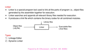
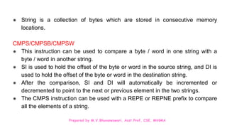
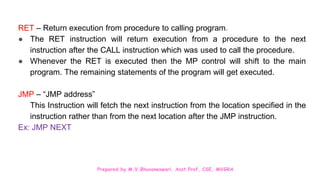
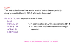
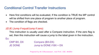
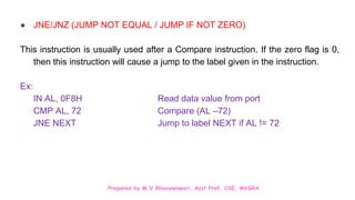
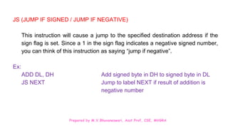
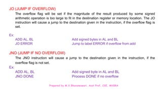
The document discusses various shift, rotate, and string manipulation instructions for the 8086 microprocessor. It provides examples of instructions like ROL, ROR, RCL, RCR, SHL, SHR, SAR, CMPS, SCAS, MOVS, LODS, and STOS. It also covers unconditional transfer instructions like CALL, RET, and JMP as well as conditional instructions like JE, JNE that check status flag values before transferring control.
![Prepared by M.V.Bhuvaneswari, Asst.Prof, CSE, MVGRA
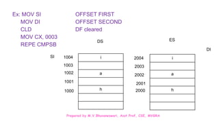
MOVS/MOVSB/MOVSW
These instructions are used to copy a byte or word from a location in the data segment
[DS] to extra segment [ES].
MOVSB – Move a string as bytes
MOVSW – Move a string as words
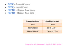
REP/REPE/REPZ/REPNE/REPNZ prefix
REP – A prefix written before string instructions
Ex: REP MOVSB – to repeat until CX=0
REPZ CMP SB – Compare string bytes until ZF=0](https://image.slidesharecdn.com/ppt-u2-240318195752-669fd50f/85/ppt-U2-Instruction-Set-of-8086-Simple-programs-pptx-22-320.jpg)
![Prepared by M.V.Bhuvaneswari, Asst.Prof, CSE, MVGRA
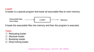
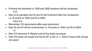
LODS/LODSB/LODSW
To copy a byte from a string location pointed by SI to AL or a word from a
string location pointed by SI to AX.
Ex: MOV SI, OFFSET_STRING
LODS STRING
First we have to initiate the source index with the offset string value and then
load that string value to the accumulator.
STOS/STOSB/STOSW
To store/copy a byte/word from accumulator to a memory location in the extra
segment [ES]. DI s used to hold the offset memory of ES](https://image.slidesharecdn.com/ppt-u2-240318195752-669fd50f/85/ppt-U2-Instruction-Set-of-8086-Simple-programs-pptx-24-320.jpg)
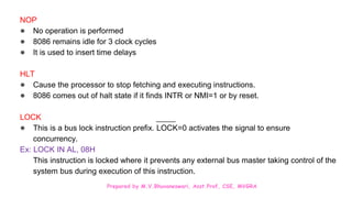
![Prepared by M.V.Bhuvaneswari, Asst.Prof, CSE, MVGRA
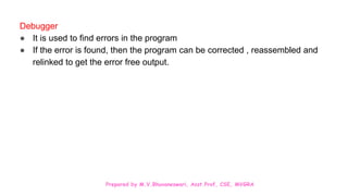
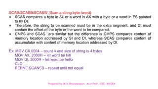
Flag Manipulation Instructions
● The flag manipulation instructions directly modify some of the flags of 8086.
STC [Set Carry Instruction]: Used to set the carry flag
CLC [Clear Carry Instruction]: Used to reset the carry flag i.e. CF=0
CMC [Complement Carry Instruction]: Used to complement the carry flag i.e.
CF=0 1 or CF=1 0
STD [Set Direction Instruction]: Set DF=1 so that SI/DI can be decremented automatically after execution
of string instruction.
CLD [Clear Direction Instruction]: Reset DF=0 so that SI/DI can be incremented automatically after
execution of string instruction.
STI [Set Interrupt flag]: If STI is set the INTR will be enabled. MP receives it when IF=1
CLI [Clear interrupt]: MP will not respond to any interrupt when IF=0 on its INTR input.](https://image.slidesharecdn.com/ppt-u2-240318195752-669fd50f/85/ppt-U2-Instruction-Set-of-8086-Simple-programs-pptx-44-320.jpg)
![Prepared by M.V.Bhuvaneswari, Asst.Prof, CSE, MVGRA
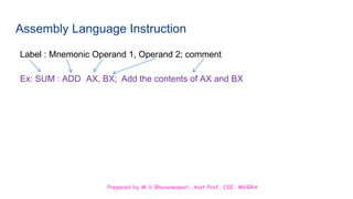
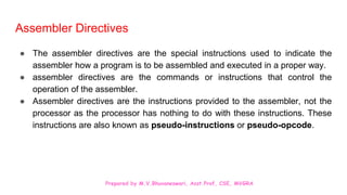
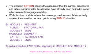
EQU
● It is used to redefine a data name or variable with another name (or) value.
● Each time when the assembler finds that name in the program, it replaces that name with
value assigned to that variable.
“[name] EQU initial value”
Ex: FACTORIAL EQU 05H whenever FACTORIAL appears in an instruction the
assembler substitutes the value 5.
● If the value has to be changed, all that has to change the EQU statement and reassemble the
program.
ORG [originate]
● This directive directs the assembler to start memory allotment for a particular segment, block
or code from the declared address.
“ORG expression”
Ex: ORG 1000H Set the location to 1000H](https://image.slidesharecdn.com/ppt-u2-240318195752-669fd50f/85/ppt-U2-Instruction-Set-of-8086-Simple-programs-pptx-56-320.jpg)
![Prepared by M.V.Bhuvaneswari, Asst.Prof, CSE, MVGRA
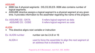
PAGE
● This directive helps to control the format of a listing of an assembled program
“PAGE [length], [width]”
Ex: PAGE 34, 96
STACK
● Provides the shortcut in stack segment
“STACK [size]”
Ex: STACK 50 This reserves 50 bytes for the stack operation
CODE – shortcut in definition of code segment
DATA – shortcut in definition of data segment
34 lines per page
Characters per line](https://image.slidesharecdn.com/ppt-u2-240318195752-669fd50f/85/ppt-U2-Instruction-Set-of-8086-Simple-programs-pptx-57-320.jpg)
![Prepared by M.V.Bhuvaneswari, Asst.Prof, CSE, MVGRA
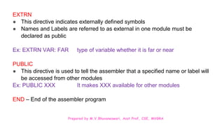
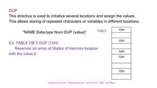
DW, DB,DD,DQ and DT
● These directives are used to define the different types of variables (or) data
types
DB [Define Byte] – 8bit
This directive is used for the purpose of allocating and initializing single or
multiple data bytes.
Ex: NUMBER DB 10H, 20H, 30H Declare array of 3bytes named ‘NUMBER’
10H
20H
30H
NUMBER](https://image.slidesharecdn.com/ppt-u2-240318195752-669fd50f/85/ppt-U2-Instruction-Set-of-8086-Simple-programs-pptx-58-320.jpg)
![Prepared by M.V.Bhuvaneswari, Asst.Prof, CSE, MVGRA
DW [Define Word]
● It defines word data type and initializes storage for word size (16bit)
Ex: Exp1 DW 1234H, 3456H, 0145 H
DD [Define Double Word] – 32 bit input (4bytes)
Ex: MEM DD 10D50F7B
DQ [Define Quad Word] – 64 bit input (8bytes)
DT [Define Ten Bytes] – 80 bit input (10 bytes)
7BH
0FH
D5H
10H
00H
00H
MEM](https://image.slidesharecdn.com/ppt-u2-240318195752-669fd50f/85/ppt-U2-Instruction-Set-of-8086-Simple-programs-pptx-59-320.jpg)
![Prepared by M.V.Bhuvaneswari, Asst.Prof, CSE, MVGRA
PTR [point]
To declare a specific type to a variable or label or memory operand. It is used to override the
declared type of variable. Operator PTR is prefixed by BYTE or WORD.
Ex: MOV AL, BYTE PTR [SI] Moves content of memory location addressed by SI
(8 bit ) to AL
EVEN
● It is used to inform the assembler to align the data beginning from an even address.
GROUP [Group related segment]
This directive is used to form logical groups of segments with similar purpose/type.
“PROGRAM GROUP CODE, DATA, STACK”
The above statement directs the loader/linker to prepare an EXE file such that CODE, DATA
and STACK segments must lie within a 64K byte memory segment that is named as
PROGRAM](https://image.slidesharecdn.com/ppt-u2-240318195752-669fd50f/85/ppt-U2-Instruction-Set-of-8086-Simple-programs-pptx-65-320.jpg)
![Prepared by M.V.Bhuvaneswari, Asst.Prof, CSE, MVGRA
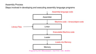
Assembler:
An Assembler is a program that translates the source file assembly language into
machine language [Binary or object code].
The Assembler generates two files
Object file
It contains the binary codes for the instruction and data. “.obj file”
Assembler list file
It contains the assembly language statements, the binary code for each instruction and
the offset for each instruction. “.asm file”
Assemblers are:
1) MASM – Microsoft macro assembler
2) TASM – Turbo assembler
The command on cmd performing this operation
C:MASMBIN>MASM test.asm;](https://image.slidesharecdn.com/ppt-u2-240318195752-669fd50f/85/ppt-U2-Instruction-Set-of-8086-Simple-programs-pptx-70-320.jpg)