Downloaded 24 times

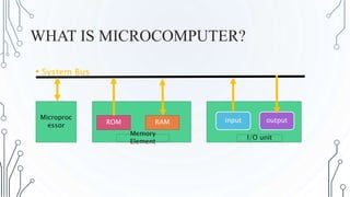
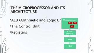
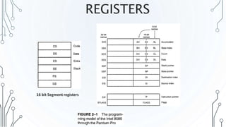
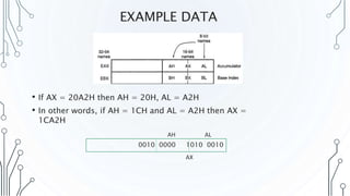
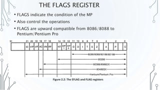


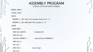
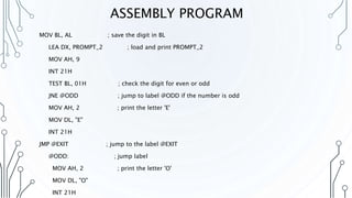
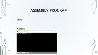


This document contains a presentation on microprocessors and assembly language programming. It includes sections on what a microcomputer is, the microprocessor architecture including the ALU and control unit, programming models and registers, examples of data in registers, the flags register and how instructions affect flags. It also includes two assembly language programs, one to check if an input is a digit, capital letter or small letter, and another to check if a number is even or odd.


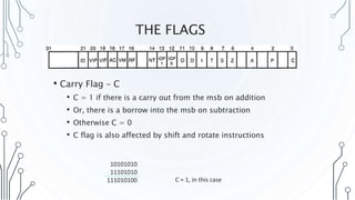
![LED [light-emitting-diode]](https://cdn.slidesharecdn.com/ss_thumbnails/led-light-emitting-diod-170815220937-thumbnail.jpg?width=640&height=640&fit=bounds)


