The document contains a PowerPoint presentation on ARM assembly language, outlining its basic and advanced instructions, branch instructions, and memory instructions, tailored for an educational setting. It includes explanations with semantic details of various ARM instructions, examples of programming tasks, and conditional logic. It is intended for use by authorized professors and educators in conjunction with a specific textbook and is prohibited from being reproduced or distributed without permission.

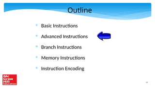
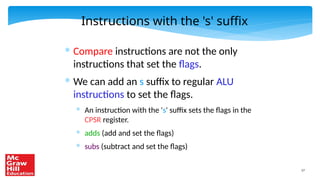
![31
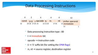
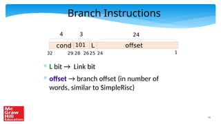
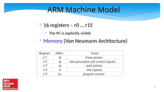
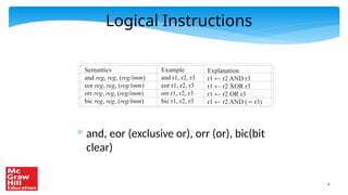
Basic Load Instruction
●
ldr r1, [r0]
ldr r1, [r0]
r0
r1
register
file
memory](https://image.slidesharecdn.com/chapter04armassembly-240930071518-f84f6b9e/85/Chapter_04_ARM_Assembly-pptx-ARM-ASSEMBLY-CODE-31-320.jpg)
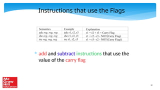
![32
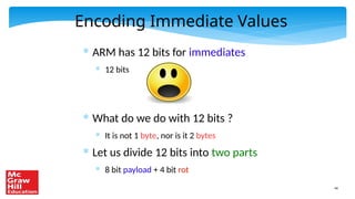
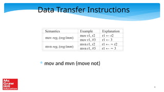
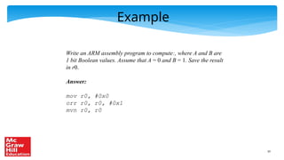
Basic Store Instruction
●
str r1, [r0]
str r1, [r0]
r0
r1
register
file
memory](https://image.slidesharecdn.com/chapter04armassembly-240930071518-f84f6b9e/85/Chapter_04_ARM_Assembly-pptx-ARM-ASSEMBLY-CODE-32-320.jpg)
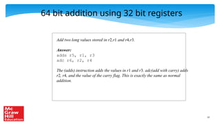
![33
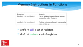
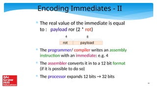
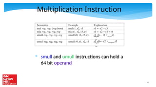
Memory Instructions with an Offset
* ldr r1, [r0, #4]
* r1 ← mem[r0 + 4]
* ldr r1, [r0, r2]
* r1 ← mem[r0 + r2]](https://image.slidesharecdn.com/chapter04armassembly-240930071518-f84f6b9e/85/Chapter_04_ARM_Assembly-pptx-ARM-ASSEMBLY-CODE-33-320.jpg)
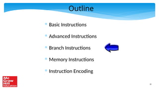
![34
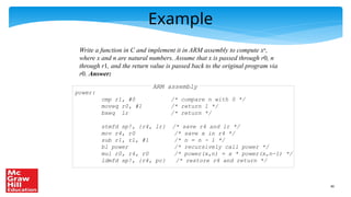
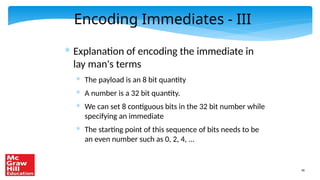
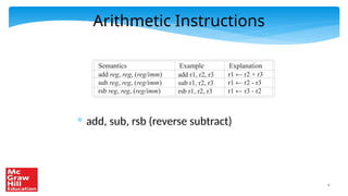
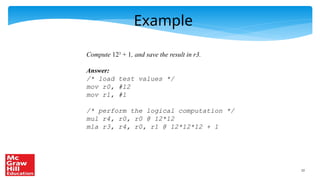
Table of Load/Store Instructions
* Note the base-scaled-index addressing mode
Semantics
ldr reg, [reg]
ldr reg, [reg, imm]
ldr reg, [reg, reg]
ldr reg, [reg, reg, shift imm]
Example
ldr r1, [r0]
ldr r1, [r0, #4]
ldr r1, [r0, r2]
ldr r1, [r0, r2, lsl #2]
Explanation
r1 ← [r0]
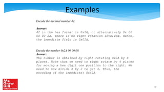
r1 ← [r0 + 4]
r1 ← [r0 + r2]
r1 ← [r0 + r2 << 2]
Addressing Mode
register-indirect
base-offset
base-index
base-scaled-index
str reg, [reg]
str reg, [reg, imm]
str reg, [reg, reg]
str reg, [reg, reg, shift imm]
str r1, [r0]
str r1, [r0, #4]
str r1, [r0, r2]
str r1, [r0, r2, lsl #2]
[r0] ← r1
[r0 + 4] ← r1
[r0 + r2] ← r1
[r0 + r2 << 2] ← r1
register-indirect
base-offset
base-index
base-scaled-index](https://image.slidesharecdn.com/chapter04armassembly-240930071518-f84f6b9e/85/Chapter_04_ARM_Assembly-pptx-ARM-ASSEMBLY-CODE-34-320.jpg)
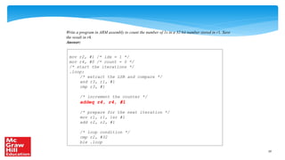
![35
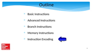
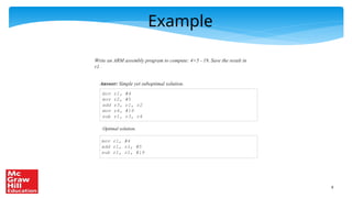
Example with Arrays
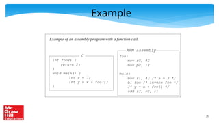
C
void addNumbers(int a[100]) {
int idx;
int sum = 0;
for (idx = 0; idx < 100; idx++){
sum = sum + a[idx];
}
}
Answer:
ARM assembly
/* base address of array a in r0 */
mov r1, #0 /* sum = 0 */
mov r2, #0 /* idx = 0 */
.loop:
ldr r3, [r0, r2, lsl #2]
add r2, r2, #1 /* idx ++ */
add r1, r1, r3 /* sum += a[idx] */
cmp r2, #100 /* loop condition */
bne .loop](https://image.slidesharecdn.com/chapter04armassembly-240930071518-f84f6b9e/85/Chapter_04_ARM_Assembly-pptx-ARM-ASSEMBLY-CODE-35-320.jpg)
![36
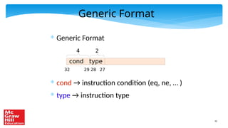
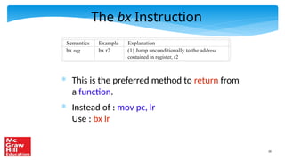
Advanced Memory Instructions
* Consider an array access again
* ldr r3, [r0, r2, lsl #2] /* access array */
* add r2, r2, #1 /* increment index */
* Can we fuse both into one instruction
* ldr r3, [r0], r2, lsl #2
* Equivalent to :
* r3 = [r0]
* r0 = r0 + r2 << 2
Post-indexed addressing
mode](https://image.slidesharecdn.com/chapter04armassembly-240930071518-f84f6b9e/85/Chapter_04_ARM_Assembly-pptx-ARM-ASSEMBLY-CODE-36-320.jpg)
![37
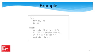
Pre-Indexed Addressing Mode
* Consider
* ldr r0, [r1, #4]!
* This is equivalent to:
* r0 mem [r1 + 4]
* r1 r1 + 4
Similar to i++ and ++i in Java/C/C++](https://image.slidesharecdn.com/chapter04armassembly-240930071518-f84f6b9e/85/Chapter_04_ARM_Assembly-pptx-ARM-ASSEMBLY-CODE-37-320.jpg)
![38
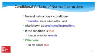
C
void addNumbers(int a[100]) {
int idx;
int sum = 0;
for (idx = 0; idx < 100; idx++){
sum = sum + a[idx];
}
}
Answer:
ARM assembly
/* base address of array a in r0 */
mov r1, #0 /* sum = 0 */
add r4, r0, #400 /* set r4 to address of a[100] */
.loop:
ldr r3, [r0], #4
add r1, r1, r3 /* sum += a[idx] */
cmp r0, r4 /* loop condition */
bne .loop
Example with Arrays](https://image.slidesharecdn.com/chapter04armassembly-240930071518-f84f6b9e/85/Chapter_04_ARM_Assembly-pptx-ARM-ASSEMBLY-CODE-38-320.jpg)