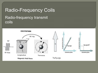
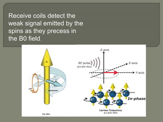
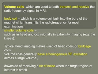
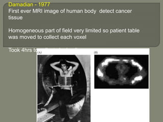
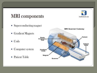
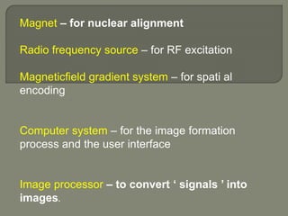
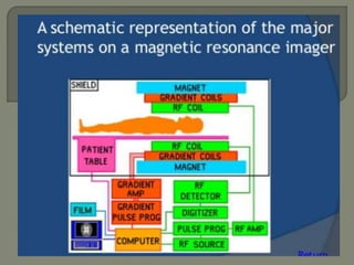
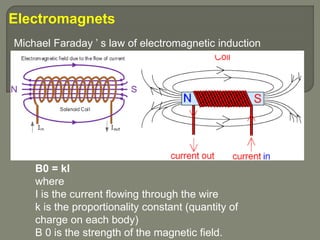
MRI machines use magnetic fields, radio waves, and computers to detect properties of living tissue. The first MRI image of the human body was obtained in 1977 and detected cancer tissue. MRI requires a magnet to align nuclear spins, radio waves to excite the spins, magnetic field gradients for spatial encoding, and a computer system to form images. Stronger magnetic fields allow for higher resolution images. Electromagnets, resistive magnets, superconducting magnets, and permanent magnets can be used to generate magnetic fields, with superconducting magnets allowing the highest field strengths. Radiofrequency coils transmit the excitation signal and receive the emitted signal used to form images.

![Magnets Earths magnetic field is 0.3-0.7G
Magnets used for imaging mostly between .5 to 7 Tesla
1] permanent magnets
2] Electromagnets
(solenoid)
3] Resistive magnets
4] Superconducting
magnets
5] hybrid magnets.](https://image.slidesharecdn.com/mrihardware-190405172031/85/Mri-hardware-7-320.jpg)


![Superconducting Magnets[niobium-titanium]
• Resistance is reduced by cooling the coils
[0k /-273c].
liquid helium is used to cool the wires and
remove resistance [liquid form only at the
extremely low temperature of −270 °C (about 4 K
]
• Without resistance, the electrical current can
flow within a closed circuit. There is no need for
any external power to be applied. The flowing of
electrical current without resistance is known as
superconductivity.](https://image.slidesharecdn.com/mrihardware-190405172031/85/Mri-hardware-17-320.jpg)

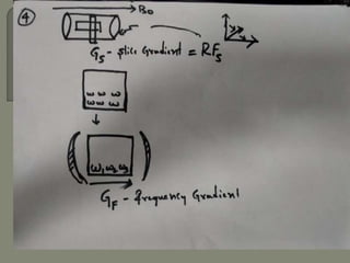
![Gradient coils
Gradient magnetic fields[G] are superimposed over the
main magnetic field[Bo].
These fields are produced by applying a current in the
gradient coils.
There are three sets of gradient coils in MR systems.](https://image.slidesharecdn.com/mrihardware-190405172031/85/Mri-hardware-19-320.jpg)
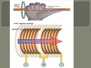


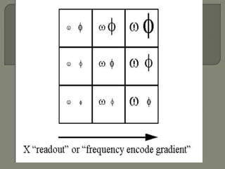
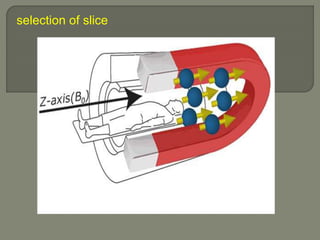
![gradient coil produces variation in the main magnetic
field
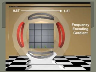
Used to
1] selection of slice -selectively excite nuclei in one
slice of tissue
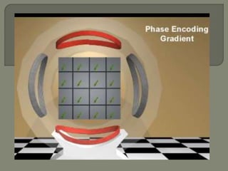
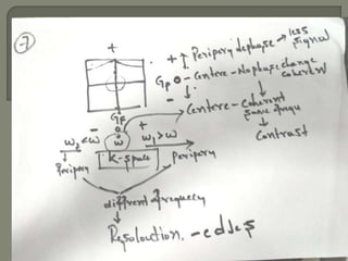
2] phase encoding
3]Frequency encoding](https://image.slidesharecdn.com/mrihardware-190405172031/85/Mri-hardware-25-320.jpg)
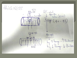
![The Larmor equation
ω0 = B0 × λ [gyrometric ratio]
wo= 1x 42.57 MHz [isocenteric]
W1=0.99x42.5
W2=1.005x42.5](https://image.slidesharecdn.com/mrihardware-190405172031/85/Mri-hardware-27-320.jpg)
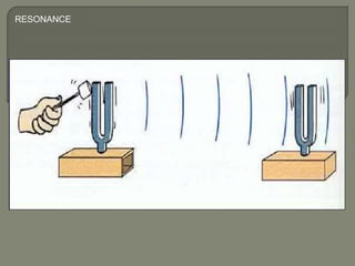
![W1=0.99x42 wo= 1x 42.57 MHz [isocenteric] 5W2=1.005x42.5
slice of tuning fork](https://image.slidesharecdn.com/mrihardware-190405172031/85/Mri-hardware-28-320.jpg)
![W1=0.99x42 wo= 1x 42.57 MHz [isocenteric] 5W2=1.005x42.5](https://image.slidesharecdn.com/mrihardware-190405172031/85/Mri-hardware-30-320.jpg)

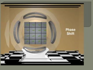
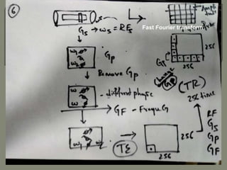
![All voxels have the same precessional frequency and
are all “in phase” after the slice select gradient [Gs] and
RF pulse](https://image.slidesharecdn.com/mrihardware-190405172031/85/Mri-hardware-33-320.jpg)