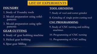
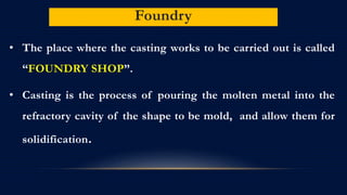
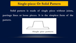
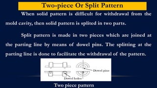
SlideShare a Scribd company logo
MANUFACTURING PROCESS LAB-III
FOUNDRY
1. Study of Foundry tools
2. Mould preparation using solid-
patterns
3. Mould preparation using split-
patterns
GEAR CUTTING
4. Study of gear hobbing machine
5. Helical gear hobbing
6. Spur gear Milling
LIST OF EXPERIMENTS
TOOL GRINDING
7. Study of tool and cutter grinder
8. Grinding of single point cutting tool
CNC PROGRAMMING
9. Study of CNC turning and milling
machines
10. Programming of CNC turning
11. Programming of CNC milling
What is Manufacturing?
Derived from the Latin word manufactus
–Manus=hand, factus= made(‘made by hand’)
– practical definition: process of converting or
processing raw materials into usable products.
Classification Of Manufacturing Process
Its classified as
 Primary shaping process
 Secondary shaping process
Primary Shaping Process
 It is the oldest manufacturing process.
 Its manufacture a product directly to its usable form.
Example : casting process
Products : channels, rods, I- section etc.,
Primary Shaping Process
Liquid state Solid state
• Forging
• Rolling
• Die forging
• Hot rolling
• Tube forming
• Upsetting
Metal casting process
• Sand mold casting
• Die casting
• Shell mold casting
• Continuous casting
Moulding process
• Injection moulding
• Compression
moulding
• Transfer moulding.
Secondary Shaping Process
• These process are carried out on the outcome of primary
shaping process like casting.
• In many cases the product from the primary forming process
are required to under go further refinement the shape and
size through various process of metal removal such as
turning and milling.
• Finishing process such as buffing, lapping are done for
surface finish on the product.
Secondary Shaping Process
solid state Super finishing
• Lapping
• Belt grinding
• Buffing
• Honing
• Cold working
• Bending
• Punching
• Rolling
• Cold extrusion
• Coining
• Thread rolling
• Spinning
• Stretch forming
Metal removal process
Foundry
• The place where the casting works to be carried out is called
“FOUNDRY SHOP”.
• Casting is the process of pouring the molten metal into the
refractory cavity of the shape to be mold, and allow them for
solidification.
Steps Involved In Casting Process
 Pattern making
 Mould making
 Casting.
Pattern and Pattern Making
Pattern is the model of the object to be mold with some
modification.
The following points should be considered while making the
pattern.
 Pattern material
 Types of pattern
 Pattern allowances
Types Of Pattern
The types of the pattern and the description of each are given
as under.
1. One piece or solid pattern
2. Two piece or split pattern
3. Cope and drag pattern
4. Three-piece or multi- piece pattern
5. Loose piece pattern
Single-piece Or Solid Pattern
Solid pattern is made of single piece without joints,
partings lines or loose pieces. It is the simplest form of the
pattern.
Two-piece Or Split Pattern
When solid pattern is difficult for withdrawal from the
mold cavity, then solid pattern is splited in two parts.
Split pattern is made in two pieces which are joined at
the parting line by means of dowel pins. The splitting at the
parting line is done to facilitate the withdrawal of the pattern.
Two piece pattern
Pattern Allowance
 Pattern are not made to the exact size of the casting to be
produced.
 It should be made little higher size than the required
castings.
 Extra size on the pattern given is called “Pattern
Allowances”
Various Tools Used In Foundry
CONT.,
1.SHOVEL
Shovel is a big tool used for mixing and transferring
moulding sand.
2. RIDDLE
It is metal sieve used for removing foreign materials such
as stones, nails etc., from the moulding sand.
3. RAMMER
It is a tool made of wood or cast iron used for packing or
ramming the moulding sand in the moulding box.
4. TROWELS
6.VENT ROD
This rod is used for making vent holes in the sand mould so
that the molten gases released during pouring of molten
metal, can easily escape from mould.
7.SPRUE PIN
It is a tapered cylindrical wooden piece. It is used for making
a sprue hole in the mould, to facilitate pouring of metal
CONT.,
MOULD PREPARATION USING SOLID- PATTERN
AIM:
To make the mould for the given solid pattern (stepped cone pulley).
MATERIAL AND TOOLS REQUIRED:
• Riser pin
• Moulding box
• Sprue pin
• Green sand
• Rammer
• Trowel
• Lifter
• Riddle
• Draw spike
• Gate cutter
• Bellow
• Vent rod
Pattern Moulding process
MOULD PREPARATION USING SOLID- PATTERN
STEPS INVOLVED TO PREPARE SAND MOULDING
WITH SOLID PATTERN
• Place the Moulding board on a horizontal surface.
• The drag box is placed above the Moulding board. Now the pattern is
kept at center of drag.
• Now parting sand in sprinkled before we keep pattern.
• Facing sand is sprinkled over the pattern to a depth of 5mm. then green
sand is filled over it.
• Proper ramming is done on the green sand to get a air tight packing.
• Excess sand is removed by strike off bar.
• The drag box is inverted upside down.
• The cope box is placed over the drag box and locked.
• The riser pin sprue pin placed at right position and green sand is filled over the
pattern.
• Proper ramming is done on the green sand to get air tight packing with strike
off bar leaving is done.
• Now riser pin and sprue pin get removed from the green sand mould. The
pattern is removed by draw spike tool.
• Gate is prepared using gate cutter and core is placed vertically inside the cavity.
• The vent holes are made with vent rod and cope.
Result:
Thus the mould is created for given stepped cone pulley.
CONT.,
MOULD PREPARATION USING SPLIT- PATTERN
AIM:
To make the mould for the given Split pattern
MATERIAL AND TOOLS REQUIRED:
• Riser pin
• Moulding box
• Sprue pin
• Green sand
• Rammer
• Trowel
• Lifter
• Riddle
• Draw spike
• Gate cutter
• Bellow
• Vent rod
MOULD PREPARATION USING SPLIT-
PATTERN
Pattern Moulding process
STEPS INVOLVED TO PREPARE GREEN
SAND MOULDING WITH SPLIT PATTERN
• Place the Moulding board on a horizontal surface.
• The drag box is placed above the Moulding board. Now one piece of
pattern is kept at center of the drag as shown in figure.
• The parting sand is spread before we keep the pattern.
• Facing sand is sprinkled over the pattern to a depth of 2mm. then
greensand is filled over it.
• Proper ramming is done on the green sand to get a air free packing.
• Excess sand is remove with strike off bar.
• The drag box is inverted upside down.
• The cope box is place over the drag box.
• Now the parting sand is sprinkled over the parting surface.
• The other piece of pattern is placed over the drag box.
• Facing sand is riddled over the pattern to a depth of 5mm. Then riser is place over the
pattern and another sprue pin above parting surface.
• Now green sand is filled over it.
• Ramming operation is done to get an air tight packing.
• Excess sand is remove with strike off bar.
• Riser pin and sprue pin gets removed from the green sand.
• Pattern is removed gently now.
• Gate is provided by the use of gate cutter.
• The vent holes are made with vent rod on the cope box.
Result:
Thus the mould is created for the given split pattern.
CONT.,
MILLING
• Milling is the cutting operation that removes metal by feeding the
work against a rotating cutter having single or multiple cutting
edges.
• Flat or curved surfaces shapes can be machined by milling with
good finish and accuracy.
• A milling machine may also be used for drilling, slotting, making
a circular profile and gear cutting by having suitable attachments.
MILLING MACHINE
MILLING MACHINE
Table overall size : 1175x230mm
Longitudinal movement:
• Auto : 560mm
• Manual : 270mm
Transverse movement:
• Auto : 250mm
• Manual : 270mm
Vertical movement(Manual) : 340mm
• Table swivel to either side : 45
• Speed range : 40 to 2000 rpm
• Feed Range : 10 to 111 mm/min
SPUR GEAR MILLING
AIM:
To cut a spur gear in the milling machine as per the given diameter.
MATERIAL REQUIRED:
Mild steel of 50mm diameter and 25mm thick.
TOOLS REQUIRED:
1. Lathe 2. Milling
• Chuck key a) Milling cutter
• Tool post key b) Spanner
• Dead centre c) Sleeve
• Parallel Block d) Indexing head
• Vernier
• Centre drill
• Drill
• Reamer
SPUR GEAR MILLING
CALCULATION SPUR GEAR
Spur gear module = 2 module (Given)
Module = PCD/Z
No of teeth = 27 (Given)
Blank diameter = (Z+2) x module
= (27+2) x 2
= 58 mm
Teeth depth = 2.25 x module
= 2.25 x 2
= 4.5 mm
Index plate movement = 40 / Z
= 40 / 27
= 1 13/27
1= One revolution
13= No. of holes
27= Index plate number
STEPS INVOLVED TO MAKE SPUR GEAR MILLING
• The given work piece has been fixed on the chuck by the use of
center bit.
• With the help of tail stock the 10 mm hole has been made on the
work piece.
• Again 20 mm drill bit has been fixed on the tailstock to provide 20
mm hole on the work piece.
• By the use of boring tool 22mm hole has been made on the work
piece.
• The work piece has been fitted on the milling machine with the help
of mandrel.
CONT.,
• Fix the cutter in the arbor rigidly and check the index mechanism
before the operation.
• Fix the work piece and cutter to zero position by raising the table
upward for contact each other.
• Give the depth of cut as 4.5mm by raising the table towards the
cutter and fed the table longitudinal to form the gear tooth
• Repeat the process, for every indexing of gear tooth
• The above procedure is repeated for the gear operation.
• The work piece has been removed from the mandrel.
STUDY OF HOBBING MACHINE
• Hobbing is a Machining process for making gears, splines, and sprockets on
a hobbing machine, which is a special type of milling machine.
• Compared to other gear forming processes it is relatively inexpensive but
still quite accurate.
• It is the most widely used gear cutting process for creating spur and helical
gears and more gears are cut by hobbing than any other process since it is
relatively quick and inexpensive.
HOBBING MACHINE
GEAR HOBBING MACHINE
SPECIFICATION
• Maximum module : 4 modules
• Maximum diameter of gear : 350mm
• Diameter of work table : 340mm
• Hob speed range (RPM) :60/75/90/115/150/190
• Maximum with cut of spur gear : 250mm
• Maximum with cut of helical gear : 200mm
HOB
• The hob is the cutter used to cut the teeth into the work piece.
• It is cylindrical in shape with Helical cutting teeth.
• Most hobs are single-thread hobs, but double and triple-thread hobs
increase production rates. The downside is that they are not as accurate
as single-thread hobs.
HELICAL GEAR HOBBING
AIM:
To machine a helical gear on the hobbing machine as per the
required dimensions.
TOOLS REQUIRED:
• Chuck key
• Tool post keys
• Mandrel single point cutting tool
• Drill bit
MATERIALS REQUIRED:
Cast iron block of diameter 63 mm and thickness 25 mm
• Centre drill and reamer
• Mandrel
• Helical gear hob.
• Spanner
HELICAL GEAR HOBBING
STEPS INVOLVED TO MAKE HELICAL GEAR HOBBING
• The given work piece has been fixed on the chuck by the use of center
bit.
• With the help of tail stock the 10 mm hole has been made on the
work piece.
• Again 20 mm drill bit has been fixed on the tailstock to provide 20
mm hole on the work piece.
• By the use of boring tool 25mm hole has been made on the work
piece,
• With the help of mandrel the work piece has been fitted on the
hobbing machine.
CONT.,
• The hob is adjusted till to touch the center of the work piece.
• Zero setting has been done by the use of hob.
• The hob has been lifted up by the way rapid motion.
• The feed has been given as 2.25 mm for three times by the use of automatic lever.
• The finished work piece has been removed for the mandrel.
Result:
Thus the helical gear was machined on the hobbing machine as per required
dimensions.
CNC MACHINE
• Computer Numerical Control (CNC) is one in which the functions
and motions of a machine tool are controlled by means of a
prepared program containing coded alphanumeric data.
• A CNC system consists of three basic elements
1. Part program (set of commands )
2. Machine Control Unit (MCU)
3. Machine tool (lathe, drill press, milling machine etc)
CNC MILLING
CNC MILLING MACHINE
SPECIFICATION
• XYZ travels : 762x305x406mm
• Table size : 1213x268mm
• Spindle speed : 4000 rpm
• Spindle : BT 40 taper
• Tool changer : 10 station automatic
CNC LATHE
CNC LATHE MACHINE
SPECIFICATION
• Cutting capacity : 406x1219mm
• XY travels : 203x1219mm
• Maximum swing : 483mm
• Spindle speed : 2000RPM
• Chuck 3 jaws 10 inch
GENERAL FORMAT OF A MANUAL CNC PROGRAM
The CNC program block generally contains the following format
N-G-X-Y-Z-A-B-C-F-S-T-M
Where,
• N – Sequence number of instructions
• G- Preparatory function
• X, Y, Z, A, B, C Co -ordinate and angular data
• F- Feed
• S- Spindle speed
• T-Tool code
• M- Miscellaneous function.
STUDY OF CNC CODES (M AND G CODES)
Miscellaneous Function (M - Code):
Miscellaneous function or "M-Codes," control the working
components that activate and deactivate coolant flow, spindle rotation,
the direction of the spindle rotation and similar activities.
• M00 Program stop
• M01 optional stop
• M02 End of program
• M03 Spindle clockwise
• M04 Spindle counterclockwise
• M05 Spindle stop
M06 Tool change (see Note below)
M08 coolant ON
M09 coolant OFF
M30 End of program
M98 Subprogram Call
STUDY OF CNC CODES (M AND G CODES
Preparatory Function (G - Code):
• Preparatory functions are G codes. G codes are designated by the letter G and a
two digit numeric value.
• These codes are the most important functions in CNC programming because they
direct the CNC system to process the coordinate data in a particular manner.
 G00 Rapid traverse
 G01 Linear interpolation with federate
 G02 Circular interpolation (clockwise)
 G03 Circular interpolation (counter clockwise)
 G17 Selection of the X, Y plane G18 Selection of the Z, X plane
 G19 Selection of the Y, Z plane G20 Selection of a freely definable
CONT.,
• G42 Path compensation right of the work piece contour
• G43 Path compensation left of the work piece contour with
altered approach
• G50 Scaling
• G54 Work coordinate systems
• G70 Inch format active
• G71 Metric format active
• G80 canned cycle "off"
G90 Absolute programming
G91 Incremental programming G92
Position preset
G94 Feed in mm / min
G95 Feed per revolution (mm / rev).
ADVANTAGES AND LIMITATIONS
• The benefits of CNC are
(1) High accuracy in manufacturing,
(2) Short production time,
(3) Greater manufacturing flexibility,
(4) Simpler fixturing,
(5) Contour machining (2 to 5 –axis machining),
(6) Reduced human error.
The drawbacks include high cost, maintenance, and the requirement of
skilled part programmer.
STEP TURNING
PROGRAMMING OF CNC TURNING
AIM:
To write a Manual part program to the given drawing and execute in
CNC lathe
MATERIAL REQUIRED:
Material : Aluminium
Size : Diameter 30 mm and length 100mm.
PROGRAM:
O00002 (Step Turning)
G28 U0 W0;
T101;
G97 S1000 M03;
G00 X30 Z10;
G00 Z2, M08;
G72 W0.5 R0.5;
G72 P10 Q20 F0.15;
N10 G00 Z0;
N20 G01 X-1;
N30 G00 Z2;
CONT.,G71 0.05 R0.5;
G71 P10 Q20 F0.15
N10 G01 X20
G01 Z0;
G01 X20 Z-30;
G01 X25 Z-30;
G01 X25 Z-60;
Result :
Thus the manual part program for the given drawing has been
executed in CNC Turning.
G01 X30 Z-100;
N20 G01X30;
G00 Z10;
M05;
M09;
G28 U0 W0;
M30;
CNC MILLING USING LINEAR INTERPOLATION
PROGRAMMING OF CNC MILLING
AIM:
To write a Manual part program to the given drawing and execute in CNC
Milling.
MATERIAL REQUIRED:
Material : Aluminium
Size : Square block 50mm x 50mm.
PROGRAM:
O00001 BILLET 50X50;
G00 G90 G54 G17 G49;
G91 G28 Z0.;
N1 T1(LINEAR);
M06;
G006 G90 G54 X0. Y0.;
G43 Z50 H01;
M03 S1000;
Z5.;
CONT.,
G01 G90 Z0. F500.;
G01 G91 Z0.25. F100.
G01 G90 G42 X-10 Y0.D01 F200.;
G01 X-10. Y10.;
X10. Y10.;
X10. Y1-0.;
X-10. Y-10.;
Result :
Thus the manual part program for the given drawing has been
executed in CNC milling
X-10. Y0.;
G01 G40 X0.Y0.;
G00 G90 Z50.;
M05;
G91 G28 Z0.Y0.;
M30;
STUDY OF TOOL AND CUTTER GRINDER
• A tool and cutter grinder is used to sharpen milling cutter and tool
bits along with a host of other cutting tools.
• It is an extremely versatile machine used to perform a variety of
grinding operations: surface, cylindrical, or complex shapes.
• The operation of this machine (in particular, the manually operated
variety) requires a high level of skill
TOOL AND CUTTER GRINDER
SPECIFICATION
• Vertical Movement Of wheel : 100 mm
• Longitudinal table Movement: 220 mm
• Transverse movement : 120mm
• Wheel tilting angle : 450
• Tool post tilting angle : 3600
• Rotating of wheel :clockwise and anticlockwise
TOOL AND CUTTER GRINDER
1. Base
2. Motor
3. Cup wheel
4. Tool post
5. Cross feed handle
6. Longitudinal table
7. Motor up and down
wheel
8. Stopper
9. Wheel guard
10. Wheel tilting angle
GRINDING OF SINGLE POINT CUTTING TOOL
AIM:
To perform a single point cutting tool by grinding operation using a tool
and cutter grinder machine as per given dimensions.
Tools Required:
• Bevel protractor
• Allen key
Material Required:
Mild steel bar 12 x 12 x 100 mm
SINGLE POINT CUTTING TOOL
STEPS INVOLVED TO MAKE SINGLE POINT
CUTTING TOOL
• The work piece is held in the tool post, which can be related about two axes
simultaneously.
• The depth of cut is given by rotating the vertical feed hand wheel by giving
to and fro motion and longitudinal movement of work table.
• The motor has been tilted to 5 degree clockwise to obtain the front
clearance angle.
• To rotate the tools post 20 degree clockwise to obtain the side cutting angle.
THANK YOU

More Related Content

What's hot

Grinding
GrindingGrinding
Grinding
Anish Ansari
 
Introduction to manufacturing process
Introduction to manufacturing processIntroduction to manufacturing process
Grinding machine
Grinding machineGrinding machine
Grinding machine
mohammed tayeeb
 
Grinding wheel designation and selection
Grinding wheel designation and selectionGrinding wheel designation and selection
Grinding wheel designation and selection
cpandiv
 
Type of grinding wheels
Type of grinding wheelsType of grinding wheels
Type of grinding wheels
garfield Tulloch
 
Hobbing
Hobbing Hobbing
Hobbing
Muhammad Awais
 
MP-1 Grinding Machine
MP-1 Grinding MachineMP-1 Grinding Machine
MP-1 Grinding Machine
Darshit Panchal
 
Grinding - Machine Tools & Metrology
Grinding - Machine Tools & MetrologyGrinding - Machine Tools & Metrology
Grinding - Machine Tools & Metrology
Krishna M Venkat
 
Grinding
GrindingGrinding
Grinding
rumaisaali2002
 
Grinding machines.kbs
Grinding machines.kbsGrinding machines.kbs
Grinding machines.kbs
Kishan Suthar
 
Manufacturing Technology- ii Unit 4
Manufacturing Technology- ii Unit 4Manufacturing Technology- ii Unit 4
Manufacturing Technology- ii Unit 4
Ravi Sankar
 
Grinding process
Grinding processGrinding process
Grinding process
HAMZA ZAKARIA
 
GRINDING
GRINDINGGRINDING
GRINDING
rmkcet
 
Methods of gear manufacturing
Methods of gear manufacturingMethods of gear manufacturing
Methods of gear manufacturing
DEBOLINAMUKHERJEE7
 
Grinding wheel
Grinding wheel Grinding wheel
Grinding wheel
Amaresh Choudhary
 
Unit 4A Grinding
Unit 4A GrindingUnit 4A Grinding
Unit 4A Grinding
Mechbytes
 
Grinding machine by- Diparsh Modh
Grinding machine by- Diparsh ModhGrinding machine by- Diparsh Modh
Grinding machine by- Diparsh Modh
Diparsh
 
Gear finishing methods
Gear finishing methodsGear finishing methods
Gear finishing methods
DEBOLINAMUKHERJEE7
 
Abrasive machining ppt_mfg_chapter26_final
Abrasive machining ppt_mfg_chapter26_finalAbrasive machining ppt_mfg_chapter26_final
Abrasive machining ppt_mfg_chapter26_final
Sanjay Nayee
 

What's hot (20)

Grinding
GrindingGrinding
Grinding
 
Grinding
GrindingGrinding
Grinding
 
Introduction to manufacturing process
Introduction to manufacturing processIntroduction to manufacturing process
Introduction to manufacturing process
 
Grinding machine
Grinding machineGrinding machine
Grinding machine
 
Grinding wheel designation and selection
Grinding wheel designation and selectionGrinding wheel designation and selection
Grinding wheel designation and selection
 
Type of grinding wheels
Type of grinding wheelsType of grinding wheels
Type of grinding wheels
 
Hobbing
Hobbing Hobbing
Hobbing
 
MP-1 Grinding Machine
MP-1 Grinding MachineMP-1 Grinding Machine
MP-1 Grinding Machine
 
Grinding - Machine Tools & Metrology
Grinding - Machine Tools & MetrologyGrinding - Machine Tools & Metrology
Grinding - Machine Tools & Metrology
 
Grinding
GrindingGrinding
Grinding
 
Grinding machines.kbs
Grinding machines.kbsGrinding machines.kbs
Grinding machines.kbs
 
Manufacturing Technology- ii Unit 4
Manufacturing Technology- ii Unit 4Manufacturing Technology- ii Unit 4
Manufacturing Technology- ii Unit 4
 
Grinding process
Grinding processGrinding process
Grinding process
 
GRINDING
GRINDINGGRINDING
GRINDING
 
Methods of gear manufacturing
Methods of gear manufacturingMethods of gear manufacturing
Methods of gear manufacturing
 
Grinding wheel
Grinding wheel Grinding wheel
Grinding wheel
 
Unit 4A Grinding
Unit 4A GrindingUnit 4A Grinding
Unit 4A Grinding
 
Grinding machine by- Diparsh Modh
Grinding machine by- Diparsh ModhGrinding machine by- Diparsh Modh
Grinding machine by- Diparsh Modh
 
Gear finishing methods
Gear finishing methodsGear finishing methods
Gear finishing methods
 
Abrasive machining ppt_mfg_chapter26_final
Abrasive machining ppt_mfg_chapter26_finalAbrasive machining ppt_mfg_chapter26_final
Abrasive machining ppt_mfg_chapter26_final
 

Similar to Mp iii lab

3gearandthreadmanufacturing-181227105343.pdf
3gearandthreadmanufacturing-181227105343.pdf3gearandthreadmanufacturing-181227105343.pdf
3gearandthreadmanufacturing-181227105343.pdf
veeramaniveltraining
 
gear and thread manufacturing,metal cutting,manufacturing processes,Productio...
gear and thread manufacturing,metal cutting,manufacturing processes,Productio...gear and thread manufacturing,metal cutting,manufacturing processes,Productio...
gear and thread manufacturing,metal cutting,manufacturing processes,Productio...
Prof.Mayur Modi
 
Types of Metal Casting Process and it's Types
Types of Metal Casting Process and it's TypesTypes of Metal Casting Process and it's Types
Types of Metal Casting Process and it's Types
Manoj Sonawane
 
Introduction to Casting
Introduction to CastingIntroduction to Casting
Introduction to Casting
Thulasikanth Vaddi
 
1 introduction of casting
1 introduction of casting1 introduction of casting
1 introduction of casting
pavankumar chunduru
 
Hydraulic cylinder piston
Hydraulic cylinder pistonHydraulic cylinder piston
Hydraulic cylinder piston
Rumeel Ahmad
 
Presentation_11_9_05.ppt Machining Process
Presentation_11_9_05.ppt Machining ProcessPresentation_11_9_05.ppt Machining Process
Presentation_11_9_05.ppt Machining Process
Muhammad Rashail Saleem
 
casting notes mpya.pptx
casting notes mpya.pptxcasting notes mpya.pptx
casting notes mpya.pptx
EmmanuelMatutu1
 
Metal casting ppt1
Metal casting ppt1Metal casting ppt1
Metal casting ppt1
maa924gourav
 
mod 6.pptx
mod 6.pptxmod 6.pptx
mod 6.pptx
AskarBasha3
 
4vrvy2np94gnchr.pptx
4vrvy2np94gnchr.pptx4vrvy2np94gnchr.pptx
4vrvy2np94gnchr.pptx
DiveshRohilla
 
Casting process
Casting processCasting process
Casting process
Dorothy Kare
 
Casting Process in Workshop -basics.pptx
Casting Process in Workshop -basics.pptxCasting Process in Workshop -basics.pptx
Casting Process in Workshop -basics.pptx
029DevendraKumarSing
 
Introduction to mp prathik
Introduction to mp prathikIntroduction to mp prathik
Introduction to mp prathik
prathik jain
 
Drilling process
Drilling processDrilling process
Drilling process
Ayush Goel
 
Manufacturing Processes Coursework
Manufacturing Processes CourseworkManufacturing Processes Coursework
Manufacturing Processes Coursework
Joseph Legan
 
castingprocessprocess in mecahnicaengineeing.ppt
castingprocessprocess in mecahnicaengineeing.pptcastingprocessprocess in mecahnicaengineeing.ppt
castingprocessprocess in mecahnicaengineeing.ppt
Praveen Kumar
 
castingprocessprocess mechanical solidification.ppt
castingprocessprocess mechanical solidification.pptcastingprocessprocess mechanical solidification.ppt
castingprocessprocess mechanical solidification.ppt
Praveen Kumar
 
castingprocessprocess mouling gating .ppt
castingprocessprocess mouling gating .pptcastingprocessprocess mouling gating .ppt
castingprocessprocess mouling gating .ppt
Praveen Kumar
 
castingprocessmechanicalenginerring .ppt
castingprocessmechanicalenginerring .pptcastingprocessmechanicalenginerring .ppt
castingprocessmechanicalenginerring .ppt
Praveen Kumar
 

Similar to Mp iii lab (20)

3gearandthreadmanufacturing-181227105343.pdf
3gearandthreadmanufacturing-181227105343.pdf3gearandthreadmanufacturing-181227105343.pdf
3gearandthreadmanufacturing-181227105343.pdf
 
gear and thread manufacturing,metal cutting,manufacturing processes,Productio...
gear and thread manufacturing,metal cutting,manufacturing processes,Productio...gear and thread manufacturing,metal cutting,manufacturing processes,Productio...
gear and thread manufacturing,metal cutting,manufacturing processes,Productio...
 
Types of Metal Casting Process and it's Types
Types of Metal Casting Process and it's TypesTypes of Metal Casting Process and it's Types
Types of Metal Casting Process and it's Types
 
Introduction to Casting
Introduction to CastingIntroduction to Casting
Introduction to Casting
 
1 introduction of casting
1 introduction of casting1 introduction of casting
1 introduction of casting
 
Hydraulic cylinder piston
Hydraulic cylinder pistonHydraulic cylinder piston
Hydraulic cylinder piston
 
Presentation_11_9_05.ppt Machining Process
Presentation_11_9_05.ppt Machining ProcessPresentation_11_9_05.ppt Machining Process
Presentation_11_9_05.ppt Machining Process
 
casting notes mpya.pptx
casting notes mpya.pptxcasting notes mpya.pptx
casting notes mpya.pptx
 
Metal casting ppt1
Metal casting ppt1Metal casting ppt1
Metal casting ppt1
 
mod 6.pptx
mod 6.pptxmod 6.pptx
mod 6.pptx
 
4vrvy2np94gnchr.pptx
4vrvy2np94gnchr.pptx4vrvy2np94gnchr.pptx
4vrvy2np94gnchr.pptx
 
Casting process
Casting processCasting process
Casting process
 
Casting Process in Workshop -basics.pptx
Casting Process in Workshop -basics.pptxCasting Process in Workshop -basics.pptx
Casting Process in Workshop -basics.pptx
 
Introduction to mp prathik
Introduction to mp prathikIntroduction to mp prathik
Introduction to mp prathik
 
Drilling process
Drilling processDrilling process
Drilling process
 
Manufacturing Processes Coursework
Manufacturing Processes CourseworkManufacturing Processes Coursework
Manufacturing Processes Coursework
 
castingprocessprocess in mecahnicaengineeing.ppt
castingprocessprocess in mecahnicaengineeing.pptcastingprocessprocess in mecahnicaengineeing.ppt
castingprocessprocess in mecahnicaengineeing.ppt
 
castingprocessprocess mechanical solidification.ppt
castingprocessprocess mechanical solidification.pptcastingprocessprocess mechanical solidification.ppt
castingprocessprocess mechanical solidification.ppt
 
castingprocessprocess mouling gating .ppt
castingprocessprocess mouling gating .pptcastingprocessprocess mouling gating .ppt
castingprocessprocess mouling gating .ppt
 
castingprocessmechanicalenginerring .ppt
castingprocessmechanicalenginerring .pptcastingprocessmechanicalenginerring .ppt
castingprocessmechanicalenginerring .ppt
 

More from Sathia Prathap

Unit (Knuckle Joint And Coupling).pptx
Unit  (Knuckle Joint And Coupling).pptxUnit  (Knuckle Joint And Coupling).pptx
Unit (Knuckle Joint And Coupling).pptx
Sathia Prathap
 
M iii laser metrology
M iii laser metrologyM iii laser metrology
M iii laser metrology
Sathia Prathap
 

More from Sathia Prathap (6)

Unit (Knuckle Joint And Coupling).pptx
Unit  (Knuckle Joint And Coupling).pptxUnit  (Knuckle Joint And Coupling).pptx
Unit (Knuckle Joint And Coupling).pptx
 
M iii laser metrology
M iii laser metrologyM iii laser metrology
M iii laser metrology
 
Unit i
Unit iUnit i
Unit i
 
Unit 1 (1)
Unit 1 (1)Unit 1 (1)
Unit 1 (1)
 
Dts key 2017
Dts key 2017Dts key 2017
Dts key 2017
 
Gear
GearGear
Gear
 

Recently uploaded

block diagram and signal flow graph representation
block diagram and signal flow graph representationblock diagram and signal flow graph representation
block diagram and signal flow graph representation
Divya Somashekar
 
ML for identifying fraud using open blockchain data.pptx
ML for identifying fraud using open blockchain data.pptxML for identifying fraud using open blockchain data.pptx
ML for identifying fraud using open blockchain data.pptx
Vijay Dialani, PhD
 
The role of big data in decision making.
The role of big data in decision making.The role of big data in decision making.
The role of big data in decision making.
ankuprajapati0525
 
Runway Orientation Based on the Wind Rose Diagram.pptx
Runway Orientation Based on the Wind Rose Diagram.pptxRunway Orientation Based on the Wind Rose Diagram.pptx
Runway Orientation Based on the Wind Rose Diagram.pptx
SupreethSP4
 
CFD Simulation of By-pass Flow in a HRSG module by R&R Consult.pptx
CFD Simulation of By-pass Flow in a HRSG module by R&R Consult.pptxCFD Simulation of By-pass Flow in a HRSG module by R&R Consult.pptx
CFD Simulation of By-pass Flow in a HRSG module by R&R Consult.pptx
R&R Consult
 
一比一原版(SFU毕业证)西蒙菲莎大学毕业证成绩单如何办理
一比一原版(SFU毕业证)西蒙菲莎大学毕业证成绩单如何办理一比一原版(SFU毕业证)西蒙菲莎大学毕业证成绩单如何办理
一比一原版(SFU毕业证)西蒙菲莎大学毕业证成绩单如何办理
bakpo1
 
Industrial Training at Shahjalal Fertilizer Company Limited (SFCL)
Industrial Training at Shahjalal Fertilizer Company Limited (SFCL)Industrial Training at Shahjalal Fertilizer Company Limited (SFCL)
Industrial Training at Shahjalal Fertilizer Company Limited (SFCL)
MdTanvirMahtab2
 
NO1 Uk best vashikaran specialist in delhi vashikaran baba near me online vas...
NO1 Uk best vashikaran specialist in delhi vashikaran baba near me online vas...NO1 Uk best vashikaran specialist in delhi vashikaran baba near me online vas...
NO1 Uk best vashikaran specialist in delhi vashikaran baba near me online vas...
Amil Baba Dawood bangali
 
Standard Reomte Control Interface - Neometrix
Standard Reomte Control Interface - NeometrixStandard Reomte Control Interface - Neometrix
Standard Reomte Control Interface - Neometrix
Neometrix_Engineering_Pvt_Ltd
 
CME397 Surface Engineering- Professional Elective
CME397 Surface Engineering- Professional ElectiveCME397 Surface Engineering- Professional Elective
CME397 Surface Engineering- Professional Elective
karthi keyan
 
weather web application report.pdf
weather web application report.pdfweather web application report.pdf
weather web application report.pdf
Pratik Pawar
 
Railway Signalling Principles Edition 3.pdf
Railway Signalling Principles Edition 3.pdfRailway Signalling Principles Edition 3.pdf
Railway Signalling Principles Edition 3.pdf
TeeVichai
 
Immunizing Image Classifiers Against Localized Adversary Attacks
Immunizing Image Classifiers Against Localized Adversary AttacksImmunizing Image Classifiers Against Localized Adversary Attacks
Immunizing Image Classifiers Against Localized Adversary Attacks
gerogepatton
 
Cosmetic shop management system project report.pdf
Cosmetic shop management system project report.pdfCosmetic shop management system project report.pdf
Cosmetic shop management system project report.pdf
Kamal Acharya
 
Top 10 Oil and Gas Projects in Saudi Arabia 2024.pdf
Top 10 Oil and Gas Projects in Saudi Arabia 2024.pdfTop 10 Oil and Gas Projects in Saudi Arabia 2024.pdf
Top 10 Oil and Gas Projects in Saudi Arabia 2024.pdf
Teleport Manpower Consultant
 
Nuclear Power Economics and Structuring 2024
Nuclear Power Economics and Structuring 2024Nuclear Power Economics and Structuring 2024
Nuclear Power Economics and Structuring 2024
Massimo Talia
 
ASME IX(9) 2007 Full Version .pdf
ASME IX(9)  2007 Full Version       .pdfASME IX(9)  2007 Full Version       .pdf
ASME IX(9) 2007 Full Version .pdf
AhmedHussein950959
 
ethical hacking in wireless-hacking1.ppt
ethical hacking in wireless-hacking1.pptethical hacking in wireless-hacking1.ppt
ethical hacking in wireless-hacking1.ppt
Jayaprasanna4
 
一比一原版(UofT毕业证)多伦多大学毕业证成绩单如何办理
一比一原版(UofT毕业证)多伦多大学毕业证成绩单如何办理一比一原版(UofT毕业证)多伦多大学毕业证成绩单如何办理
一比一原版(UofT毕业证)多伦多大学毕业证成绩单如何办理
ydteq
 
一比一原版(IIT毕业证)伊利诺伊理工大学毕业证成绩单专业办理
一比一原版(IIT毕业证)伊利诺伊理工大学毕业证成绩单专业办理一比一原版(IIT毕业证)伊利诺伊理工大学毕业证成绩单专业办理
一比一原版(IIT毕业证)伊利诺伊理工大学毕业证成绩单专业办理
zwunae
 

Recently uploaded (20)

block diagram and signal flow graph representation
block diagram and signal flow graph representationblock diagram and signal flow graph representation
block diagram and signal flow graph representation
 
ML for identifying fraud using open blockchain data.pptx
ML for identifying fraud using open blockchain data.pptxML for identifying fraud using open blockchain data.pptx
ML for identifying fraud using open blockchain data.pptx
 
The role of big data in decision making.
The role of big data in decision making.The role of big data in decision making.
The role of big data in decision making.
 
Runway Orientation Based on the Wind Rose Diagram.pptx
Runway Orientation Based on the Wind Rose Diagram.pptxRunway Orientation Based on the Wind Rose Diagram.pptx
Runway Orientation Based on the Wind Rose Diagram.pptx
 
CFD Simulation of By-pass Flow in a HRSG module by R&R Consult.pptx
CFD Simulation of By-pass Flow in a HRSG module by R&R Consult.pptxCFD Simulation of By-pass Flow in a HRSG module by R&R Consult.pptx
CFD Simulation of By-pass Flow in a HRSG module by R&R Consult.pptx
 
一比一原版(SFU毕业证)西蒙菲莎大学毕业证成绩单如何办理
一比一原版(SFU毕业证)西蒙菲莎大学毕业证成绩单如何办理一比一原版(SFU毕业证)西蒙菲莎大学毕业证成绩单如何办理
一比一原版(SFU毕业证)西蒙菲莎大学毕业证成绩单如何办理
 
Industrial Training at Shahjalal Fertilizer Company Limited (SFCL)
Industrial Training at Shahjalal Fertilizer Company Limited (SFCL)Industrial Training at Shahjalal Fertilizer Company Limited (SFCL)
Industrial Training at Shahjalal Fertilizer Company Limited (SFCL)
 
NO1 Uk best vashikaran specialist in delhi vashikaran baba near me online vas...
NO1 Uk best vashikaran specialist in delhi vashikaran baba near me online vas...NO1 Uk best vashikaran specialist in delhi vashikaran baba near me online vas...
NO1 Uk best vashikaran specialist in delhi vashikaran baba near me online vas...
 
Standard Reomte Control Interface - Neometrix
Standard Reomte Control Interface - NeometrixStandard Reomte Control Interface - Neometrix
Standard Reomte Control Interface - Neometrix
 
CME397 Surface Engineering- Professional Elective
CME397 Surface Engineering- Professional ElectiveCME397 Surface Engineering- Professional Elective
CME397 Surface Engineering- Professional Elective
 
weather web application report.pdf
weather web application report.pdfweather web application report.pdf
weather web application report.pdf
 
Railway Signalling Principles Edition 3.pdf
Railway Signalling Principles Edition 3.pdfRailway Signalling Principles Edition 3.pdf
Railway Signalling Principles Edition 3.pdf
 
Immunizing Image Classifiers Against Localized Adversary Attacks
Immunizing Image Classifiers Against Localized Adversary AttacksImmunizing Image Classifiers Against Localized Adversary Attacks
Immunizing Image Classifiers Against Localized Adversary Attacks
 
Cosmetic shop management system project report.pdf
Cosmetic shop management system project report.pdfCosmetic shop management system project report.pdf
Cosmetic shop management system project report.pdf
 
Top 10 Oil and Gas Projects in Saudi Arabia 2024.pdf
Top 10 Oil and Gas Projects in Saudi Arabia 2024.pdfTop 10 Oil and Gas Projects in Saudi Arabia 2024.pdf
Top 10 Oil and Gas Projects in Saudi Arabia 2024.pdf
 
Nuclear Power Economics and Structuring 2024
Nuclear Power Economics and Structuring 2024Nuclear Power Economics and Structuring 2024
Nuclear Power Economics and Structuring 2024
 
ASME IX(9) 2007 Full Version .pdf
ASME IX(9)  2007 Full Version       .pdfASME IX(9)  2007 Full Version       .pdf
ASME IX(9) 2007 Full Version .pdf
 
ethical hacking in wireless-hacking1.ppt
ethical hacking in wireless-hacking1.pptethical hacking in wireless-hacking1.ppt
ethical hacking in wireless-hacking1.ppt
 
一比一原版(UofT毕业证)多伦多大学毕业证成绩单如何办理
一比一原版(UofT毕业证)多伦多大学毕业证成绩单如何办理一比一原版(UofT毕业证)多伦多大学毕业证成绩单如何办理
一比一原版(UofT毕业证)多伦多大学毕业证成绩单如何办理
 
一比一原版(IIT毕业证)伊利诺伊理工大学毕业证成绩单专业办理
一比一原版(IIT毕业证)伊利诺伊理工大学毕业证成绩单专业办理一比一原版(IIT毕业证)伊利诺伊理工大学毕业证成绩单专业办理
一比一原版(IIT毕业证)伊利诺伊理工大学毕业证成绩单专业办理
 

Mp iii lab

  • 2. FOUNDRY 1. Study of Foundry tools 2. Mould preparation using solid- patterns 3. Mould preparation using split- patterns GEAR CUTTING 4. Study of gear hobbing machine 5. Helical gear hobbing 6. Spur gear Milling LIST OF EXPERIMENTS TOOL GRINDING 7. Study of tool and cutter grinder 8. Grinding of single point cutting tool CNC PROGRAMMING 9. Study of CNC turning and milling machines 10. Programming of CNC turning 11. Programming of CNC milling
  • 3. What is Manufacturing? Derived from the Latin word manufactus –Manus=hand, factus= made(‘made by hand’) – practical definition: process of converting or processing raw materials into usable products.
  • 4. Classification Of Manufacturing Process Its classified as  Primary shaping process  Secondary shaping process
  • 5. Primary Shaping Process  It is the oldest manufacturing process.  Its manufacture a product directly to its usable form. Example : casting process Products : channels, rods, I- section etc.,
  • 6. Primary Shaping Process Liquid state Solid state • Forging • Rolling • Die forging • Hot rolling • Tube forming • Upsetting Metal casting process • Sand mold casting • Die casting • Shell mold casting • Continuous casting Moulding process • Injection moulding • Compression moulding • Transfer moulding.
  • 7. Secondary Shaping Process • These process are carried out on the outcome of primary shaping process like casting. • In many cases the product from the primary forming process are required to under go further refinement the shape and size through various process of metal removal such as turning and milling. • Finishing process such as buffing, lapping are done for surface finish on the product.
  • 8. Secondary Shaping Process solid state Super finishing • Lapping • Belt grinding • Buffing • Honing • Cold working • Bending • Punching • Rolling • Cold extrusion • Coining • Thread rolling • Spinning • Stretch forming Metal removal process
  • 9. Foundry • The place where the casting works to be carried out is called “FOUNDRY SHOP”. • Casting is the process of pouring the molten metal into the refractory cavity of the shape to be mold, and allow them for solidification.
  • 10. Steps Involved In Casting Process  Pattern making  Mould making  Casting.
  • 11. Pattern and Pattern Making Pattern is the model of the object to be mold with some modification. The following points should be considered while making the pattern.  Pattern material  Types of pattern  Pattern allowances
  • 12. Types Of Pattern The types of the pattern and the description of each are given as under. 1. One piece or solid pattern 2. Two piece or split pattern 3. Cope and drag pattern 4. Three-piece or multi- piece pattern 5. Loose piece pattern
  • 13. Single-piece Or Solid Pattern Solid pattern is made of single piece without joints, partings lines or loose pieces. It is the simplest form of the pattern.
  • 14. Two-piece Or Split Pattern When solid pattern is difficult for withdrawal from the mold cavity, then solid pattern is splited in two parts. Split pattern is made in two pieces which are joined at the parting line by means of dowel pins. The splitting at the parting line is done to facilitate the withdrawal of the pattern. Two piece pattern
  • 15. Pattern Allowance  Pattern are not made to the exact size of the casting to be produced.  It should be made little higher size than the required castings.  Extra size on the pattern given is called “Pattern Allowances”
  • 16. Various Tools Used In Foundry
  • 17. CONT., 1.SHOVEL Shovel is a big tool used for mixing and transferring moulding sand. 2. RIDDLE It is metal sieve used for removing foreign materials such as stones, nails etc., from the moulding sand. 3. RAMMER It is a tool made of wood or cast iron used for packing or ramming the moulding sand in the moulding box. 4. TROWELS
  • 18. 6.VENT ROD This rod is used for making vent holes in the sand mould so that the molten gases released during pouring of molten metal, can easily escape from mould. 7.SPRUE PIN It is a tapered cylindrical wooden piece. It is used for making a sprue hole in the mould, to facilitate pouring of metal CONT.,
  • 19. MOULD PREPARATION USING SOLID- PATTERN AIM: To make the mould for the given solid pattern (stepped cone pulley). MATERIAL AND TOOLS REQUIRED: • Riser pin • Moulding box • Sprue pin • Green sand • Rammer • Trowel • Lifter • Riddle • Draw spike • Gate cutter • Bellow • Vent rod
  • 20. Pattern Moulding process MOULD PREPARATION USING SOLID- PATTERN
  • 21. STEPS INVOLVED TO PREPARE SAND MOULDING WITH SOLID PATTERN • Place the Moulding board on a horizontal surface. • The drag box is placed above the Moulding board. Now the pattern is kept at center of drag. • Now parting sand in sprinkled before we keep pattern. • Facing sand is sprinkled over the pattern to a depth of 5mm. then green sand is filled over it. • Proper ramming is done on the green sand to get a air tight packing. • Excess sand is removed by strike off bar. • The drag box is inverted upside down.
  • 22. • The cope box is placed over the drag box and locked. • The riser pin sprue pin placed at right position and green sand is filled over the pattern. • Proper ramming is done on the green sand to get air tight packing with strike off bar leaving is done. • Now riser pin and sprue pin get removed from the green sand mould. The pattern is removed by draw spike tool. • Gate is prepared using gate cutter and core is placed vertically inside the cavity. • The vent holes are made with vent rod and cope. Result: Thus the mould is created for given stepped cone pulley. CONT.,
  • 23. MOULD PREPARATION USING SPLIT- PATTERN AIM: To make the mould for the given Split pattern MATERIAL AND TOOLS REQUIRED: • Riser pin • Moulding box • Sprue pin • Green sand • Rammer • Trowel • Lifter • Riddle • Draw spike • Gate cutter • Bellow • Vent rod
  • 24. MOULD PREPARATION USING SPLIT- PATTERN Pattern Moulding process
  • 25. STEPS INVOLVED TO PREPARE GREEN SAND MOULDING WITH SPLIT PATTERN • Place the Moulding board on a horizontal surface. • The drag box is placed above the Moulding board. Now one piece of pattern is kept at center of the drag as shown in figure. • The parting sand is spread before we keep the pattern. • Facing sand is sprinkled over the pattern to a depth of 2mm. then greensand is filled over it. • Proper ramming is done on the green sand to get a air free packing. • Excess sand is remove with strike off bar. • The drag box is inverted upside down. • The cope box is place over the drag box.
  • 26. • Now the parting sand is sprinkled over the parting surface. • The other piece of pattern is placed over the drag box. • Facing sand is riddled over the pattern to a depth of 5mm. Then riser is place over the pattern and another sprue pin above parting surface. • Now green sand is filled over it. • Ramming operation is done to get an air tight packing. • Excess sand is remove with strike off bar. • Riser pin and sprue pin gets removed from the green sand. • Pattern is removed gently now. • Gate is provided by the use of gate cutter. • The vent holes are made with vent rod on the cope box. Result: Thus the mould is created for the given split pattern. CONT.,
  • 27. MILLING • Milling is the cutting operation that removes metal by feeding the work against a rotating cutter having single or multiple cutting edges. • Flat or curved surfaces shapes can be machined by milling with good finish and accuracy. • A milling machine may also be used for drilling, slotting, making a circular profile and gear cutting by having suitable attachments.
  • 29. MILLING MACHINE Table overall size : 1175x230mm Longitudinal movement: • Auto : 560mm • Manual : 270mm Transverse movement: • Auto : 250mm • Manual : 270mm Vertical movement(Manual) : 340mm • Table swivel to either side : 45 • Speed range : 40 to 2000 rpm • Feed Range : 10 to 111 mm/min
  • 30. SPUR GEAR MILLING AIM: To cut a spur gear in the milling machine as per the given diameter. MATERIAL REQUIRED: Mild steel of 50mm diameter and 25mm thick. TOOLS REQUIRED: 1. Lathe 2. Milling • Chuck key a) Milling cutter • Tool post key b) Spanner • Dead centre c) Sleeve • Parallel Block d) Indexing head • Vernier • Centre drill • Drill • Reamer
  • 32. CALCULATION SPUR GEAR Spur gear module = 2 module (Given) Module = PCD/Z No of teeth = 27 (Given) Blank diameter = (Z+2) x module = (27+2) x 2 = 58 mm Teeth depth = 2.25 x module = 2.25 x 2 = 4.5 mm Index plate movement = 40 / Z = 40 / 27 = 1 13/27 1= One revolution 13= No. of holes 27= Index plate number
  • 33. STEPS INVOLVED TO MAKE SPUR GEAR MILLING • The given work piece has been fixed on the chuck by the use of center bit. • With the help of tail stock the 10 mm hole has been made on the work piece. • Again 20 mm drill bit has been fixed on the tailstock to provide 20 mm hole on the work piece. • By the use of boring tool 22mm hole has been made on the work piece. • The work piece has been fitted on the milling machine with the help of mandrel.
  • 34. CONT., • Fix the cutter in the arbor rigidly and check the index mechanism before the operation. • Fix the work piece and cutter to zero position by raising the table upward for contact each other. • Give the depth of cut as 4.5mm by raising the table towards the cutter and fed the table longitudinal to form the gear tooth • Repeat the process, for every indexing of gear tooth • The above procedure is repeated for the gear operation. • The work piece has been removed from the mandrel.
  • 35. STUDY OF HOBBING MACHINE • Hobbing is a Machining process for making gears, splines, and sprockets on a hobbing machine, which is a special type of milling machine. • Compared to other gear forming processes it is relatively inexpensive but still quite accurate. • It is the most widely used gear cutting process for creating spur and helical gears and more gears are cut by hobbing than any other process since it is relatively quick and inexpensive.
  • 37. GEAR HOBBING MACHINE SPECIFICATION • Maximum module : 4 modules • Maximum diameter of gear : 350mm • Diameter of work table : 340mm • Hob speed range (RPM) :60/75/90/115/150/190 • Maximum with cut of spur gear : 250mm • Maximum with cut of helical gear : 200mm
  • 38. HOB • The hob is the cutter used to cut the teeth into the work piece. • It is cylindrical in shape with Helical cutting teeth. • Most hobs are single-thread hobs, but double and triple-thread hobs increase production rates. The downside is that they are not as accurate as single-thread hobs.
  • 39. HELICAL GEAR HOBBING AIM: To machine a helical gear on the hobbing machine as per the required dimensions. TOOLS REQUIRED: • Chuck key • Tool post keys • Mandrel single point cutting tool • Drill bit MATERIALS REQUIRED: Cast iron block of diameter 63 mm and thickness 25 mm • Centre drill and reamer • Mandrel • Helical gear hob. • Spanner
  • 41. STEPS INVOLVED TO MAKE HELICAL GEAR HOBBING • The given work piece has been fixed on the chuck by the use of center bit. • With the help of tail stock the 10 mm hole has been made on the work piece. • Again 20 mm drill bit has been fixed on the tailstock to provide 20 mm hole on the work piece. • By the use of boring tool 25mm hole has been made on the work piece, • With the help of mandrel the work piece has been fitted on the hobbing machine.
  • 42. CONT., • The hob is adjusted till to touch the center of the work piece. • Zero setting has been done by the use of hob. • The hob has been lifted up by the way rapid motion. • The feed has been given as 2.25 mm for three times by the use of automatic lever. • The finished work piece has been removed for the mandrel. Result: Thus the helical gear was machined on the hobbing machine as per required dimensions.
  • 43. CNC MACHINE • Computer Numerical Control (CNC) is one in which the functions and motions of a machine tool are controlled by means of a prepared program containing coded alphanumeric data. • A CNC system consists of three basic elements 1. Part program (set of commands ) 2. Machine Control Unit (MCU) 3. Machine tool (lathe, drill press, milling machine etc)
  • 45. CNC MILLING MACHINE SPECIFICATION • XYZ travels : 762x305x406mm • Table size : 1213x268mm • Spindle speed : 4000 rpm • Spindle : BT 40 taper • Tool changer : 10 station automatic
  • 47. CNC LATHE MACHINE SPECIFICATION • Cutting capacity : 406x1219mm • XY travels : 203x1219mm • Maximum swing : 483mm • Spindle speed : 2000RPM • Chuck 3 jaws 10 inch
  • 48. GENERAL FORMAT OF A MANUAL CNC PROGRAM The CNC program block generally contains the following format N-G-X-Y-Z-A-B-C-F-S-T-M Where, • N – Sequence number of instructions • G- Preparatory function • X, Y, Z, A, B, C Co -ordinate and angular data • F- Feed • S- Spindle speed • T-Tool code • M- Miscellaneous function.
  • 49. STUDY OF CNC CODES (M AND G CODES) Miscellaneous Function (M - Code): Miscellaneous function or "M-Codes," control the working components that activate and deactivate coolant flow, spindle rotation, the direction of the spindle rotation and similar activities. • M00 Program stop • M01 optional stop • M02 End of program • M03 Spindle clockwise • M04 Spindle counterclockwise • M05 Spindle stop M06 Tool change (see Note below) M08 coolant ON M09 coolant OFF M30 End of program M98 Subprogram Call
  • 50. STUDY OF CNC CODES (M AND G CODES Preparatory Function (G - Code): • Preparatory functions are G codes. G codes are designated by the letter G and a two digit numeric value. • These codes are the most important functions in CNC programming because they direct the CNC system to process the coordinate data in a particular manner.  G00 Rapid traverse  G01 Linear interpolation with federate  G02 Circular interpolation (clockwise)  G03 Circular interpolation (counter clockwise)  G17 Selection of the X, Y plane G18 Selection of the Z, X plane  G19 Selection of the Y, Z plane G20 Selection of a freely definable
  • 51. CONT., • G42 Path compensation right of the work piece contour • G43 Path compensation left of the work piece contour with altered approach • G50 Scaling • G54 Work coordinate systems • G70 Inch format active • G71 Metric format active • G80 canned cycle "off" G90 Absolute programming G91 Incremental programming G92 Position preset G94 Feed in mm / min G95 Feed per revolution (mm / rev).
  • 52. ADVANTAGES AND LIMITATIONS • The benefits of CNC are (1) High accuracy in manufacturing, (2) Short production time, (3) Greater manufacturing flexibility, (4) Simpler fixturing, (5) Contour machining (2 to 5 –axis machining), (6) Reduced human error. The drawbacks include high cost, maintenance, and the requirement of skilled part programmer.
  • 54. PROGRAMMING OF CNC TURNING AIM: To write a Manual part program to the given drawing and execute in CNC lathe MATERIAL REQUIRED: Material : Aluminium Size : Diameter 30 mm and length 100mm. PROGRAM: O00002 (Step Turning) G28 U0 W0; T101; G97 S1000 M03; G00 X30 Z10; G00 Z2, M08; G72 W0.5 R0.5; G72 P10 Q20 F0.15; N10 G00 Z0; N20 G01 X-1; N30 G00 Z2;
  • 55. CONT.,G71 0.05 R0.5; G71 P10 Q20 F0.15 N10 G01 X20 G01 Z0; G01 X20 Z-30; G01 X25 Z-30; G01 X25 Z-60; Result : Thus the manual part program for the given drawing has been executed in CNC Turning. G01 X30 Z-100; N20 G01X30; G00 Z10; M05; M09; G28 U0 W0; M30;
  • 56. CNC MILLING USING LINEAR INTERPOLATION
  • 57. PROGRAMMING OF CNC MILLING AIM: To write a Manual part program to the given drawing and execute in CNC Milling. MATERIAL REQUIRED: Material : Aluminium Size : Square block 50mm x 50mm. PROGRAM: O00001 BILLET 50X50; G00 G90 G54 G17 G49; G91 G28 Z0.; N1 T1(LINEAR); M06; G006 G90 G54 X0. Y0.; G43 Z50 H01; M03 S1000; Z5.;
  • 58. CONT., G01 G90 Z0. F500.; G01 G91 Z0.25. F100. G01 G90 G42 X-10 Y0.D01 F200.; G01 X-10. Y10.; X10. Y10.; X10. Y1-0.; X-10. Y-10.; Result : Thus the manual part program for the given drawing has been executed in CNC milling X-10. Y0.; G01 G40 X0.Y0.; G00 G90 Z50.; M05; G91 G28 Z0.Y0.; M30;
  • 59. STUDY OF TOOL AND CUTTER GRINDER • A tool and cutter grinder is used to sharpen milling cutter and tool bits along with a host of other cutting tools. • It is an extremely versatile machine used to perform a variety of grinding operations: surface, cylindrical, or complex shapes. • The operation of this machine (in particular, the manually operated variety) requires a high level of skill
  • 60. TOOL AND CUTTER GRINDER SPECIFICATION • Vertical Movement Of wheel : 100 mm • Longitudinal table Movement: 220 mm • Transverse movement : 120mm • Wheel tilting angle : 450 • Tool post tilting angle : 3600 • Rotating of wheel :clockwise and anticlockwise
  • 61. TOOL AND CUTTER GRINDER 1. Base 2. Motor 3. Cup wheel 4. Tool post 5. Cross feed handle 6. Longitudinal table 7. Motor up and down wheel 8. Stopper 9. Wheel guard 10. Wheel tilting angle
  • 62. GRINDING OF SINGLE POINT CUTTING TOOL AIM: To perform a single point cutting tool by grinding operation using a tool and cutter grinder machine as per given dimensions. Tools Required: • Bevel protractor • Allen key Material Required: Mild steel bar 12 x 12 x 100 mm
  • 64. STEPS INVOLVED TO MAKE SINGLE POINT CUTTING TOOL • The work piece is held in the tool post, which can be related about two axes simultaneously. • The depth of cut is given by rotating the vertical feed hand wheel by giving to and fro motion and longitudinal movement of work table. • The motor has been tilted to 5 degree clockwise to obtain the front clearance angle. • To rotate the tools post 20 degree clockwise to obtain the side cutting angle.