Downloaded 372 times

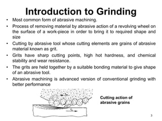
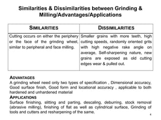
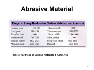
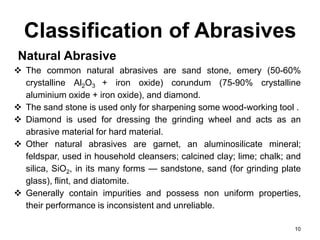
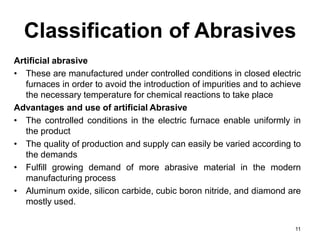
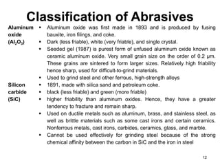
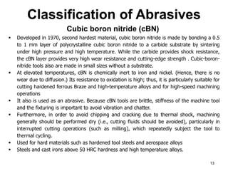
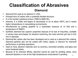
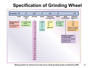
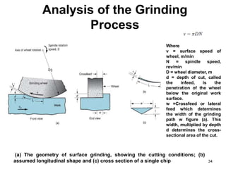


The document provides an overview of grinding as an abrasive machining process, detailing its methods, equipment, and applications. It discusses the composition and specifications of grinding wheels, including the types of abrasives used, such as aluminum oxide and diamond, as well as bonding materials like vitrified and resin bonds. Additionally, it covers the properties of abrasives, their classifications, and the importance of particles' size and bonding materials in the grinding process.


