Downloaded 23 times
![IJRET: International Journal of Research in Engineering and Technology eISSN: 2319-1163 | pISSN: 2321-7308
__________________________________________________________________________________________
Volume: 03 Special Issue: 03 | May-2014 | NCRIET-2014, Available @ http://www.ijret.org 20
MODERN SOLAR POWERED IRRIGATION SYSYTEM BY USING ARM Basava Sidramappa Dhanne1, Sachin Kedare2, Shiva Sidramapp Dhanne3 1M.Tech Embedded Systems CMRCET, A.P India 2M.Tech Embedded & VLSI Design MREC A.P India 3BE Mechanical Engineering, BKIT, Bhalki, Karnataka India Abstract This paper gives information related automatic supply of water to fields, automation of system is provided with modules and soil moisture sensor, the source to generate electricity through renewable resources, we prefer sunlight as the main source. The objective is to supply water for the fields through solar powered water pump and automate the system for better management of resources. The farmer (user) can water the fields from any place using GSM technique which provides an acknowledgement message about the situation. The main advantage of this project is optimizing the power usage through water resource management and also saving government’s free subsidiary electricity. This proves an efficient and economy way of irrigation and this will automate the agriculture sector Keywords: solar, arm processor, GSM, dc motor
----------------------------------------------------------------------***--------------------------------------------------------------------- I. INTRODUCTION Gradually decreasing energy sources and increasing demand for energy in recent years, makes more efficient and positive use of current water resources together with global warming and drought. Agriculture in India has a significant history. Today, India ranks second worldwide in farm output. Agriculture and allied sectors like forestry and fisheries accounted for 16.6% of the GDP in 2009, about 50% of the total workforce. The economic contribution of agriculture to India's GDP is steadily declining with the country's broad- based economic growth. Still, agriculture is demographically the broadest economic sector and plays a significant role in the overall socio-economic fabric of India. Energy of pumps used for the agricultural irrigation is generally provided from electrical energy or fossil fuels. Since fossil fuels commence to annihilate besides its increasing of prices and hazards to environment alternative energy seeking efforts has become inevitable also in agricultural sector [1]. Solar energy that is sensitive to environment, clean and requiring no maintenance is an alternative renewable energy source especially for countries like Turkey having a high amount of annual solar irradiation rate. In India most of the power generation is carried out by conventional energy sources, coal and mineral oil-based power plants which contribute heavily to greenhouse gases emission [2]. Setting up of new power plants is inevitably dependent on import of highly volatile fossil fuels. Thus, it is essential to tackle the energy crisis through judicious utilization of abundantly available renewable energy resources, such as biomass energy, solar energy, wind energy, geothermal energy and Ocean energy [3-6].
Though our country claims to have developed in terms of science and technology, erratic power supply or complete breakdown for hours together has almost become routine today. If this be the case for urban dwellers, think about the farmers living in remote villages. They need power for irrigating their crops, or lighting their cattle sheds. What can they do? The reasons for having large gap between requirement and consumed energy could be the wastage of electrical energy. The foremost reason can be that the power supplied for agricultural needs is during the night hours. Farmers Switch on the pump motor and leave it „on‟ for the whole night. Farmers do not bother to switch off the pump motor when the land is filled with sufficient water level [7- 11]. This is the main source of wastage of electrical energy from the grid. 2. SOLAR SYSTEM IRRIGATION IN INDIA
Providing adequate and quality power to domestic and other consumers remains one of the major challenges before the country. There is also an increasing concern to reduce reliance on fossil fuels in meeting power needs and opting for cleaner and greener fuels instead. With about 300 clear sunny days in a year, India’s potential for producing solar power is far more than its current total energy consumption. However, presently the amount of solar energy produced in India is insignificant compared to other energy resources. Therefore, solar power is being increasingly utilized worldwide as a renewable source of energy. India has huge untapped solar off-grid opportunities, given its ability to provide energy to vast untapped remote rural areas, the scope of providing backup power to cell towers and its inherent potential to replace precious fossil fuels. The solar PV off-grid opportunities in India are huge, given the fact that over 400 million people do not have access to grid connected electricity. The off-grid opportunities are significant, given the cost involved in off-](https://image.slidesharecdn.com/modernsolarpoweredirrigationsysytembyusingarm-140822050026-phpapp02/85/Modern-solar-powered-irrigation-sysytem-by-using-arm-1-320.jpg)
![IJRET: International Journal of Research in Engineering and Technology eISSN: 2319-1163 | pISSN: 2321-7308
__________________________________________________________________________________________
Volume: 03 Special Issue: 03 | May-2014 | NCRIET-2014, Available @ http://www.ijret.org 21
grid applications when compared to huge financial investments to be made to set up grids. Moreover, specific government incentives to promote off-grid applications, rapid expansion of wireless telecom and telecom companies‟ desire to reduce operating cost for base stations are also expected to prompt. Growth in off-grid opportunities. The potential of replacing huge usage of kerosene used for lighting rural homes makes off-grid applications desirable. Off-grid PV application examples include remote village electrification, power irrigation pump sets, telecom towers, back-up power generation, captive power generation and city, street, billboard and highway lighting. The government’s solar mission envisages off-grid applications reaching 2,000 Mw by 2022 and deploying 20 million solar lighting systems for rural areas. 3. DESIGN OF AUTOMATIC PHOTOIRRIGATION SYSTEM Water is the primary source of life for mankind and one of the most basic necessities for rural development. The rural demand for water for crop irrigation and domestic water supplies is increasing. At the same time, rainfall is decreasing in many arid countries, so surface water is becoming scarce.
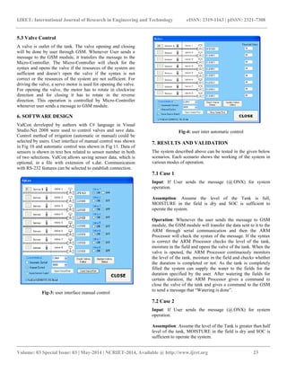
Fig-1: Solar powered irrigation system
As these trends continue, mechanized water pumping will become the only reliable alternative for lifting water from the ground. Diesel, gasoline, and kerosene pumps have traditionally been used to pump water. However, reliable solar (photovoltaic [PV])are now emerging on the market and are rapidly becoming more attractive than the traditional power sources. These technologies powered by renewable energy sources (solar), are especially useful in remote locations where a steady fuel supply is problematic and skilled maintenance personnel are scarce.
4. DESIGN METHODOLOGY The main objective of this project is to watering to the fields and simultaneously generating the power for pumping water from storage tank there is lots of technology tried to reduce the power consumption but not succeed our technique is power generation and efficient utilization of generated power Main components are required in this automations are solar panel, arm processor, sensors, dc motors, relay, battery.](https://image.slidesharecdn.com/modernsolarpoweredirrigationsysytembyusingarm-140822050026-phpapp02/85/Modern-solar-powered-irrigation-sysytem-by-using-arm-2-320.jpg)
![IJRET: International Journal of Research in Engineering and Technology eISSN: 2319-1163 | pISSN: 2321-7308
__________________________________________________________________________________________
Volume: 03 Special Issue: 03 | May-2014 | NCRIET-2014, Available @ http://www.ijret.org 22
In this process whenever the sunlight falls on solar panel its liberates the electrons in the material creates the motion in the electrons to generate the DC currentThis dc power is stored in the battery so that the pump can operate even in the night time by discharging the battery. The other end of the battery is connected to the relay and relay is connected to DC PUMP A water tank is present in order to store the water for watering the fields.
SOLAR PANEL
Water outlet
Fig-2: solar powered irrigation system
If the user (farmer) sends the text message via mobile phone as [@.ONX] it checks the level of tank and condition of moisture in field depending on the level of tank the operations takes place. We can know the level of water with the help of level sensors. If the task is completed then the GSM module sends the simple message as “WATERING IS COMPLETE” to the user. If the task is not completed it sends message as “WATERING IS NOT COMPLETED LAGGING RESOURCES”. The state of charge of the battery is sensed by charge sensor and sends it to ARM PROCESSOR and the level sensor sense the level of water in tank and sends it to the PROCESSOR. 5. HARDWARE DESIGN 5.1 PV Sizing Different size of PV modules will produce different amount of power. To find out the sizing of PV module, the total peak watt produced needs. The peak watt (WP) produced depends on size of the PV module and climate of site location. To determine the sizing of the PV modules, calculate as follows: Step 1: Calculation of Total Load Connected Total Load Connected = [D.C Pump Power Rating * Time of usage] + [Remaining Components Power Rating* Time of usage]
Step 2: Calculation of Total PV Panels Energy Needed Total PV panel’s energy needed= Total Load Connected + Losses
Step 3: Calculation of Total WP of PV Panel Capacity Needed Total WP of PV Panel Capacity Needed = Total PV panels energy needed/ No of Illumination hours Step 4: Calculation of No. of PV Panels Required No. of PV panels = Total WP of PV panel capacity needed/ Rating of the PV Panel 5.2 Battery Sizing The Amp-hour (Ah) Capacity of a battery tries to quantify the amount of usable energy it can store at a nominal voltage. All things equal, the greater the physical volume of a battery, the larger its total storage capacity. Step 1: Calculation of total Load Connected Total Load Connected = Sum of all appliances (power rating of each device * Time of usage) STEP 2: Calculation of Battery (Ah) Total Load Connected*Days of Autonomy/ Battery Losses*Depth of Discharge* N.B.V
ARM9
RELAY
DC MOTOR
GSM MODULE
VALVE CONTROL](https://image.slidesharecdn.com/modernsolarpoweredirrigationsysytembyusingarm-140822050026-phpapp02/85/Modern-solar-powered-irrigation-sysytem-by-using-arm-3-320.jpg)
![IJRET: International Journal of Research in Engineering and Technology eISSN: 2319-1163 | pISSN: 2321-7308
__________________________________________________________________________________________
Volume: 03 Special Issue: 03 | May-2014 | NCRIET-2014, Available @ http://www.ijret.org 24
Operation: Whenever the user sends the message to GSM module, the GSM module will transfer the data sent to it to the ARM processor through serial communication and then the ARM processor will check the syntax of the message. If the syntax is correct the ARM processor checks the level of the tank, moisture in the field and opens the valve of the tank. In this case the system will operate in two modes: In the first mode only Watering will be done to the fields by using water in the tank. ARM will continuously monitor the level of the tank, moisture in the field and checks whether the duration is completed or not. Until the level of the water in the tank reaches below the half of the tank the system will operate in the first mode and will continuously monitors the level of the tank and checks whether the duration is completed or not. Whenever the level of the water in the tank reaches below the one half of the tank the system will operate in the second mode. In the second mode whenever the level of the water in the tank reaches below the half of the tank the ARM will check the SOC of the battery in order to ON the motor. As SOC of the battery in this case is sufficient enough to operate the system the ARM will ON the motor and pumps the water to the tank through Motor. As the water is pumped to the tank watering is done to the fields. In this mode both the valve and motor are in operation. After the duration is completed, ARM closes the valve and gives a command to the GSM to send a message that “Watering is done”. 7.3 Case 3 Input: If User sends the message (@.ONX) for system operation. Assumption: Assume the level of the Tank is below the half level of the tank, MOISTURE in the field is dry and SOC is sufficient to operate the system for the duration specified by the user. Operation: Whenever the user sends the message to GSM module, the GSM module will transfer the data sent to it to the ARM through serial communication and then the ARM will check the syntax of the message. If the syntax is correct the ARM checks the level of the tank, moisture in the field As the level of the water in this case is below the half level of the tank, moisture is dry the ARM now will check the SOC of the battery in order to ON the motor to pump the water into the tank for watering the fields. As the SOC is sufficient to operate the system for the certain duration, the motor is operated by ARM and it opens the valve of the tank. The motor and the valve will be in the operation until the duration is completed. Once duration is over, ARM closes the valve and gives a command to the GSM to send a message that “Watering is done”.
7.4 CASE 4
Input: If User sends the message (@.ONX) for system operation.
Assumption: Assume the level of the Tank is below the half of the tank, MOISTURE in the field is wet and SOC is not sufficient to operate the system for the duration specified by the user. Operation: Whenever the user sends the message to GSM module, the GSM module will transfer the data sent to it to the ARM through serial communication and then the ARM will check the syntax of the message. If the syntax is correct the ARM checks the level of the tank, moisture in the field as the level of water is below the half level of the tank, and moisture in the field is wet. The ARM now will check the SOC of the battery in order to ON the motor to pump the water into the tank for watering the fields. As the SOC is not sufficient to operate the system for the certain duration, the motor is operated and valve is opened until the SOC is sufficient. After that the ARM gives a command to the GSM to send a message that “Watering not done, lagging resources”. 8. CONCLUSIONS The history of agriculture dates back thousands of years, and the development has been driven and defined by greatly different climates, cultures and technologies. The main contribution of this paper is to give a overview of project model which will greatly develop the irrigation system in India. The automation of an irrigation system will largely reduce the gap between requirement and consumed energy and further conserves the resources thereby reducing the wastage of resource. In addition to this system removes workmanship that is needed for flooding irrigation. Environmental pollution is prevented with renewable energy and energy production from local resources is encouraged. An advantage of system is that system needs no maintenance. The use of this photo irrigation system will be able to contribute to the socio- economic development. REFERENCES [1]. Y. Kim and R. G. Evans, ―Software design for wireless sensor-based site-specific irrigation‖, Computers and Electronics in Agriculture,vol. 66, pp. 159–165, 2009. [2]. W. R. Anis and H. M. B. Metwally, ―Dynamic performance of a directly coupled PV pumping system,‖ Solar Energy, vol. 53, pp. 369–377, 1994. [3]. W. Lawrance, B. Wichert, and D. Hgridge, ―Simulation and performance of a photo-voltaic pumping system,‖ Power Electronics and Drive System, vol. 1, pp. 513-518, 1995.
[4]. C. L. PuttaSwamy, B. Singh, B. P. Singh, and S. S. Murthy, ―Experimental investigations on a permanent magnet brushless DC motor fed by PV array for water](https://image.slidesharecdn.com/modernsolarpoweredirrigationsysytembyusingarm-140822050026-phpapp02/85/Modern-solar-powered-irrigation-sysytem-by-using-arm-5-320.jpg)
![IJRET: International Journal of Research in Engineering and Technology eISSN: 2319-1163 | pISSN: 2321-7308
__________________________________________________________________________________________
Volume: 03 Special Issue: 03 | May-2014 | NCRIET-2014, Available @ http://www.ijret.org 25
pumping system,‖ J. Sol. Energy Eng., vol. 122, pp.1663-1668, 2000. [5]. R. E. Katan, V. G. Agelidis, and C. V. Nayar, ―Performance analysis of a solar water pumping system‖, Power Electronics, Drives and Energy Systems for Industrial Growth, vol. 1, pp. 81-87, 1996. [6]. M. Dursun and A. Saygin, ―A switched reluctance motor driver with boost converter designed for a photovoltaic array irrigation system‖, Journal of The Institute of Science and Technology of Erciyes University, vol. 22, pp. 57-65, 2006. [7]. M. Dursun, ―Education purpose switched reluctance motor driver for photovoltaic array irrigation system,‖ in Proc. I. International Vocational and Technologies Congress, İstanbul, pp.595-601. 2005. [8]. M. Dursun and A. Saygin, ―System Analysis of switched reluctance motor driver with boost converter for a photovoltaic array irrigation system,‖ in 3rd Renewable Energy Sources Symposium, Mersin, pp. 57–62. 2005. [9]. M. Kolhe, J. C. Joshi, and D. P. Kothari, ―Performance analysis of a directly coupled photovoltaic water-pumping system,‖ IEEE Trans. On Energy Conv., vol. 19, pp. 613-618, 2004 [10]. S. Singer and J. Appelbaum, ―Starting characteristics of direct current motors powered by solar cells,‖ IEEE Trans. Energy Conversion, vol. 8, pp. 47–53, 1993. [11]. M. Kolhe, S. Kolhe, and J. C. Joshi, ―Determination of magnetic field constant of DC permanent magnet motor powered by photovoltaic for maximum mechanical energy output,‖ Renewable Energy, vol. 21, pp. 563–571, 2000.](https://image.slidesharecdn.com/modernsolarpoweredirrigationsysytembyusingarm-140822050026-phpapp02/85/Modern-solar-powered-irrigation-sysytem-by-using-arm-6-320.jpg)

This paper presents a solar-powered irrigation system that automates water supply using an ARM processor and GSM technology, enabling farmers to manage irrigation remotely. The system optimizes power usage while addressing energy crises through renewable resources, particularly solar energy, suitable for areas with inadequate electricity access. It highlights the efficiency and economic advantages of this method for irrigation in India, contributing to resource conservation and socio-economic development.


