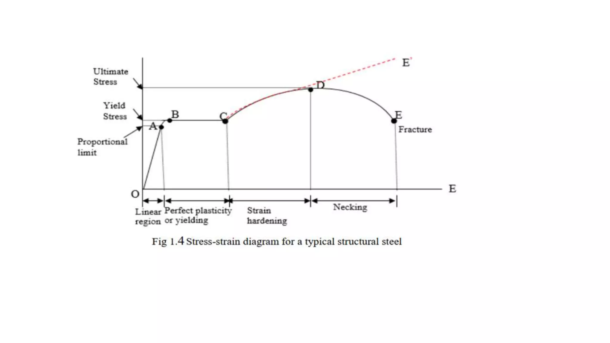
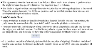
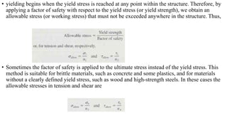
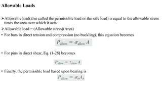
Basic mechanical engineering (BMET-101/102) unit 5 part-1 simple stress and ...Varun Pratap Singh
Download Link: https://sites.google.com/view/varunpratapsingh/teaching-engagements
UNIT-5
Stress and Strain Analysis Simple stress and strain: Introduction, Normal shear stresses, Stress-strain diagrams for ductile and brittle materials, Elastic constants, One dimensional loading of members of varying cross section, Strain energy, Thermal stresses.
Compound stress and strains: Introduction, State of plane stress, Principal stress and strain, Mohr’s circle for stress and strain.
Pure Bending of Beams: Introduction, Simple bending theory, Stress in beams of different cross sections.
Torsion: Introduction, Torsion of Shafts of circular section, Torque and Twist, Shear stress due to Torque.
This slide introduces the concept of simple strain, a term used in mechanics to describe the deformation of a material under an applied force. The slide includes a diagram illustrating the deformation of a rectangular object under a tensile force, as well as a formula for calculating strain. Simple strain is a fundamental concept in the study of materials and mechanics, and understanding it is essential for many engineering applications
KuberTENes Birthday Bash Guadalajara - K8sGPT first impressionsVictor Morales
K8sGPT is a tool that analyzes and diagnoses Kubernetes clusters. This presentation was used to share the requirements and dependencies to deploy K8sGPT in a local environment.
Literature Review Basics and Understanding Reference Management.pptxDr Ramhari Poudyal
Three-day training on academic research focuses on analytical tools at United Technical College, supported by the University Grant Commission, Nepal. 24-26 May 2024
ACEP Magazine edition 4th launched on 05.06.2024Rahul
This document provides information about the third edition of the magazine "Sthapatya" published by the Association of Civil Engineers (Practicing) Aurangabad. It includes messages from current and past presidents of ACEP, memories and photos from past ACEP events, information on life time achievement awards given by ACEP, and a technical article on concrete maintenance, repairs and strengthening. The document highlights activities of ACEP and provides a technical educational article for members.
CHINA’S GEO-ECONOMIC OUTREACH IN CENTRAL ASIAN COUNTRIES AND FUTURE PROSPECTjpsjournal1
The rivalry between prominent international actors for dominance over Central Asia's hydrocarbon
reserves and the ancient silk trade route, along with China's diplomatic endeavours in the area, has been
referred to as the "New Great Game." This research centres on the power struggle, considering
geopolitical, geostrategic, and geoeconomic variables. Topics including trade, political hegemony, oil
politics, and conventional and nontraditional security are all explored and explained by the researcher.
Using Mackinder's Heartland, Spykman Rimland, and Hegemonic Stability theories, examines China's role
in Central Asia. This study adheres to the empirical epistemological method and has taken care of
objectivity. This study analyze primary and secondary research documents critically to elaborate role of
china’s geo economic outreach in central Asian countries and its future prospect. China is thriving in trade,
pipeline politics, and winning states, according to this study, thanks to important instruments like the
Shanghai Cooperation Organisation and the Belt and Road Economic Initiative. According to this study,
China is seeing significant success in commerce, pipeline politics, and gaining influence on other
governments. This success may be attributed to the effective utilisation of key tools such as the Shanghai
Cooperation Organisation and the Belt and Road Economic Initiative.
HEAP SORT ILLUSTRATED WITH HEAPIFY, BUILD HEAP FOR DYNAMIC ARRAYS.
Heap sort is a comparison-based sorting technique based on Binary Heap data structure. It is similar to the selection sort where we first find the minimum element and place the minimum element at the beginning. Repeat the same process for the remaining elements.
Online aptitude test management system project report.pdfKamal Acharya
The purpose of on-line aptitude test system is to take online test in an efficient manner and no time wasting for checking the paper. The main objective of on-line aptitude test system is to efficiently evaluate the candidate thoroughly through a fully automated system that not only saves lot of time but also gives fast results. For students they give papers according to their convenience and time and there is no need of using extra thing like paper, pen etc. This can be used in educational institutions as well as in corporate world. Can be used anywhere any time as it is a web based application (user Location doesn’t matter). No restriction that examiner has to be present when the candidate takes the test.
Every time when lecturers/professors need to conduct examinations they have to sit down think about the questions and then create a whole new set of questions for each and every exam. In some cases the professor may want to give an open book online exam that is the student can take the exam any time anywhere, but the student might have to answer the questions in a limited time period. The professor may want to change the sequence of questions for every student. The problem that a student has is whenever a date for the exam is declared the student has to take it and there is no way he can take it at some other time. This project will create an interface for the examiner to create and store questions in a repository. It will also create an interface for the student to take examinations at his convenience and the questions and/or exams may be timed. Thereby creating an application which can be used by examiners and examinee’s simultaneously.
Examination System is very useful for Teachers/Professors. As in the teaching profession, you are responsible for writing question papers. In the conventional method, you write the question paper on paper, keep question papers separate from answers and all this information you have to keep in a locker to avoid unauthorized access. Using the Examination System you can create a question paper and everything will be written to a single exam file in encrypted format. You can set the General and Administrator password to avoid unauthorized access to your question paper. Every time you start the examination, the program shuffles all the questions and selects them randomly from the database, which reduces the chances of memorizing the questions.
Hierarchical Digital Twin of a Naval Power SystemKerry Sado
A hierarchical digital twin of a Naval DC power system has been developed and experimentally verified. Similar to other state-of-the-art digital twins, this technology creates a digital replica of the physical system executed in real-time or faster, which can modify hardware controls. However, its advantage stems from distributing computational efforts by utilizing a hierarchical structure composed of lower-level digital twin blocks and a higher-level system digital twin. Each digital twin block is associated with a physical subsystem of the hardware and communicates with a singular system digital twin, which creates a system-level response. By extracting information from each level of the hierarchy, power system controls of the hardware were reconfigured autonomously. This hierarchical digital twin development offers several advantages over other digital twins, particularly in the field of naval power systems. The hierarchical structure allows for greater computational efficiency and scalability while the ability to autonomously reconfigure hardware controls offers increased flexibility and responsiveness. The hierarchical decomposition and models utilized were well aligned with the physical twin, as indicated by the maximum deviations between the developed digital twin hierarchy and the hardware.
2. LINEAR ELASTICITY, HOOKE'S LAW, AND POISSON'S RATIO
When a material behaves elastically and also exhibits a linear relationship between stress and strain, it is said to be
linearly elastic.
From the origin O to the point called proportional limit (A), the stress-strain curve is a straight line. This linear
relation between elongation and the axial force causing was first noticed by Sir Robert Hooke in1678 and is called
Hooke's Law that within the proportional limit, the stress is directly proportional to strain
The linear relationship between stress and strain for a bar in simple tension or compression is expressed by the
equation
The modulus of elasticity has relatively large values for materials that are very stiff, such as structural metals. Steel
has a modulus of approximately 210 GPa for aluminum, values around 73 Gpa are typical. More flexible materials
have a lower modulus—values for plastics range from 0.7 to 14 GPa.
3. ELASTIC LIMIT: The elastic limit is the limit beyond which the material will no longer go back to its
original shape when the load is removed, or it is the maximum stress that may e developed such that there is no
permanent or residual deformation when the load is entirely removed.
ELASTIC AND PLASTIC RANGES: The region in stress-strain diagram from O to A is called the
elastic range. The region beyond A is called the plastic range.
YIELD POINT: Yield point is the point at which the material will have an appreciable elongation or
yielding without any increase in load.
ULTIMATE STRENGTH: The maximum ordinate in the stress-strain diagram is the ultimate strength
or tensile strength.
RAPTURE STRENGTH: Rapture strength is the strength of the material at rupture. This is also known
as the breaking strength
4. Poisson's Ratio
When a prismatic bar is loaded in tension, the axial elongation is accompanied by
lateral contraction
It is found that for an elastic material the lateral strain is proportional to the
longitudinal strain,
The ratio of the strain in the lateral direction to the strain in the axial direction is
known as Poisson's ratio and is denoted by the Greek letter ν (nu); thus
•
• The lateral strain at any point in a bar is proportional to the axial strain at that
same point if the material is linearly elastic
5. In order for the lateral strains to be the same throughout the bar, additional conditions must be met
1) the axial force must be constant throughout the length of the bar. so that the axial strain is constant.
2) the material must be homogeneous,
3) that the elastic properties must be the same in all directional perpendicular to the longitudinal axis. (E is the
same in both directions).
• Materials having the same properties in all directions (axial, lateral, and in between) are said to be isotropic.
• If the properties differ in various directions, the material is anisotropic
Volumetric Strain Because the dimensions of a bar in tension or compression are changed when the load is
applied, the volume of the bar changes too. The change in volume can be calculated from the axial and lateral
strains
The dashed line in the fig below shows the shape of the element after the load is applied. The elongation of the
element in the direction of loading is aε, where ε is the axial strain.
6. • Thus, the final dimensions of the element are a (1 + ε), b (1 - νε), and c (1 - νε),
and the final volume is
• Vf = abc (1 + ε) (1 - ν ε) (1 - ν ε) =
• As ε is very small compared to unity, its square and cube are negligible in
comparison to ε itself. Therefore, the final volume of the element is
• The change in volume is,
• The unit volume change, i.e. volumetric strain
• The quantity e is also known as the dilatation. The preceding equations for volume
changes may also be used for compression, in which case the axial strain ε is
negative and the volume of the bar decreases.
7. SHEAR STRESS AND STRAIN
• shear stress is also known as tangential stress in a member of cross-sectional area, A subjected
to an tangential /parallel force V is therefore obtained by dividing the magnitude V of the load
by the area A
8. consider the bolted connection shown in Fig. l-25a. This connection consists of a
flat bar A. a clevis C, and a bolt B that passes through holes in the bar and clevis.
Under the action of the tensile loads P. the bar and clevis will press against the
bolt in bearing, and contact stresses, called bearing stresses, will be developed.
In addition, the bar and clevis tend to shear the bolt, that is, cut through it.
This tendency is resisted by shear stresses in the bolt.
9. The actual distribution of the bearing stresses is difficult to determine, so it is customary
to assume that the stresses are uniformly distributed.
Based upon the assumption of uniform distribution, we can calculate an average bearing
stress by dividing the total bearing force by the bearing area A
The bearing area is defined as the projected area of the curved bearing surface.
For instance, consider the bearing stresses labeled 1. The projected area Ab on which
they act is a rectangle having a height equal to the thickness of the clevis and a width
equal to the diameter of the bolt.
Also, the bearing force Fb represented by the stresses labeled 1 is equal to P/2.
The same area and the same force apply to the stresses labeled 3.
Now consider the bearing stresses between the flat bar and the bolt (the stresses labeled
2). For these stresses, the bearing area Ab, is a rectangle with height equal to the
thickness of the flat bar and width equal to the bolt diameter. The corresponding bearing
force is equal to the load P
10. The free-body diagram of Fig. l-25c shows that there is a tendency to shear the
bolt along cross sections mn and pq
We see that shear forces V act over the cut surfaces of the bolt.
In this particular example there are two planes of shear {mn and pq), and so the
bolt is said to be in double shear.
In double shear, each of the shear forces is equal to one-half of the total load
transmitted by the bolt, that is, V — P/2.
These stresses act parallel to the cut surface.
The average shear stress on the cross section of a bolt is obtained by dividing the
total shear force V by the area A of the cross section on which it acts, as follows
the area A is the cross-sectional area of the bolt and the shear force V equals P/2
11. • Equality of Shear Stresses on Perpendicular Planes
• A couple consists of two parallel forces that are equal in magnitude and opposite in •
direction.
• In summary, we have arrived at the following general observations:
1. Shear stresses on opposite (and parallel) faces of an element are equal in magnitude and
opposite in direction.
2. Shear stresses on adjacent (and perpendicular) faces of an element are equal in magnitude and
have directions such that both stresses point toward, or both point away from, the line of
intersection of the faces.
12. Shear Strain
the shear stresses have no tendency to elongate or shorten the element in the x, y, and z
directions—in other words, the lengths of the sides of the element do not change.
Instead, the shear stresses produce a change in the shape of the element (Fig. l-28b). The
original element, which is a rectangular parallelepiped, is deformed into an oblique
parallelepiped, and the front and rear faces become rhomboids.
• For instance, the angles at points q and s, which were π/2 before deformation, are reduced by a
small angle γ to π/2 - γ (Fig. l-28b). At the same time, the angles at points p and r are increased
to π/2 - γ The angle γ is a measure of the distortion, or change in shape, of the element and is
called the shear strain. Because shear strain is an angle, it is measured in degrees or radians.
Sign Conventions for Shear Stresses and Strains
• A shear stress acting on a positive face of an element is positive if it acts
in the positive direction of one of the coordinate axes and negative if it acts in the negative
direction of an axis.
• A shear stress acting on a negative face of an element is positive if it acts in the negative
direction of an axis and negative if it acts in a positive direction. Thus, all shear stresses
shown in Fig. l-28a are positive.
13. The sign convention for shear strains is as follows: Shear strain in an element is positive when
the angle between two positive faces (or two negative faces) is reduced.
The strain is negative when the angle between two positive (or two negative) faces is increased.
Thus, the strains shown in Fig. l-28b are positive, and we see that positive shear stresses are
accompanied by positive shear strains.
Hooke's Law in Shear
• These properties in shear are usually about half as large as those in tension. For instance, the
yield stress for structural steel in shear is 0.5 to 0.6 times the yield stress in tension.
• For many materials, the initial part of the shear stress-strain diagram is a straight line through
the origin, just as it is in tension. For this linearly elastic region, the shear stress and shear strain
are proportional, and therefore we have the following equation for Hooke's law in shear:
• G is the shear modulus of elasticity (also called the modulus of rigidity). The shear modulus G
has the same units as the tension modulus E, namely, psi or ksi in USCS units and pascals in SI
units.
14. ALLOWABLE STRESSES AND ALLOWABLE LOADS
Factors to be considered in design include functionality, strength, appearance, economics, and
environmental protection. However, when studying mechanics of materials, our principal design
interest is strength, that is, the capacity of the object to support or transmit loads.
Objects that must sustain loads include buildings, machines, containers, trucks, aircraft, ships,
and the like. For simplicity, we will refer to all such objects as structures; thus, a structure is any
object that must support or transmit loads.
• If structural failure is to be avoided, the loads that a structure is capable of supporting must be
greater than the loads it will be subjected to when in service.
• The actual strength of a structure must exceed the required strength. The ratio of the actual
strength to the required strength is called the factor of safety n:
• Of course, the factor of safety must be greater than 1 .0 if failure is to be avoided. Depending
upon the circumstances, factors of safety from slightly above 1.0 to as much as 10 are used.
15. • yielding begins when the yield stress is reached at any point within the structure. Therefore, by
applying a factor of safety with respect to the yield stress (or yield strength), we obtain an
allowable stress (or working stress) that must not be exceeded anywhere in the structure. Thus,
• Sometimes the factor of safety is applied to the ultimate stress instead of the yield stress. This
method is suitable for brittle materials, such as concrete and some plastics, and for materials
without a clearly defined yield stress, such as wood and high-strength steels. In these cases the
allowable stresses in tension and shear are
16. Allowable Loads
Allowable load(also called the permissible load or the safe load) is equal to the allowable stress
times the area over which it acts:
Allowable load = (Allowable stress)(Area)
• For bars in direct tension and compression (no buckling), this equation becomes
• For pins in direct shear, Eq. (1-28) becomes
• Finally, the permissible load based upon bearing is
17. Problem
1) A metal bar ABC having two different cross-sectional areas is loaded by an axial force P (see figure). Parts AB
and BC are circular in cross section with diameters 1.75 in. and 1.25 in., respectively. If the normal stress in part
AB is 5000 psi. what is the normal stress in part BC
2. Calculate the compressive stress σc in the circular piston rod (see figure) when a force P=40 N is applied to the
brake pedal. Assume that the line of action of the force P is parallel to the piston rod, which has diameter 5 mm. Also,
the other dimensions shown in the figure (50 mm and 225 mm) are measured perpendicular to the line of action of the
force P.
18. 3. A prismatic bar of circular cross section is loaded by tensile forces P = 120 kN (see figure). The
bar has length L = 3.0 m and diameter d = 30 mm. It is made of aluminum alloy (2014-T6) with
modulus of elasticity E = 73 GPa and Poisson's ratio v = 1/3. Calculate the elongation ẟ, the
decrease in diameter Δd, and the increase in volume ΔV of the bar.
4. Three steel plates, each 16 mm thick, are joined by two 20-mm diameter rivets as shown in the
figure. (a) If the load P =50 kN, what is the largest bearing stress acting on the rivets?
• (b) If the ultimate shear stress for the rivets is 180 MPa, what force Pult is required to cause the
rivets to fail in shear? (Disregard friction between the plates.)