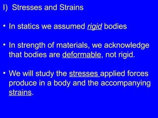
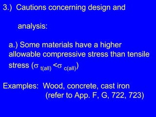
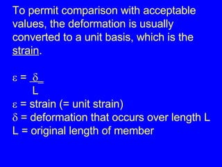
This document summarizes key concepts in stresses and strains from strength of materials including:
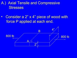
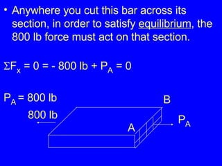
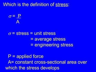
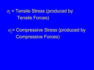
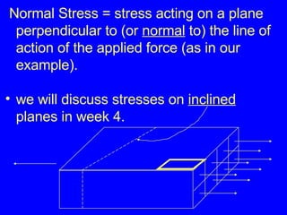
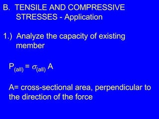
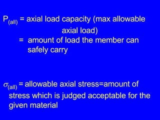
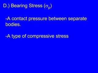
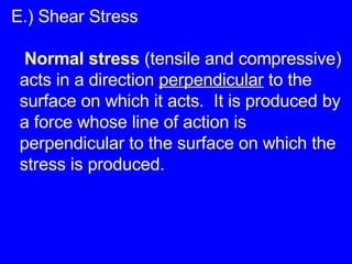
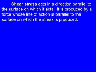
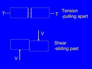
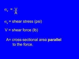
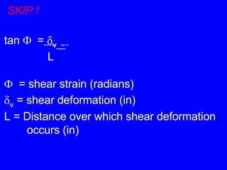
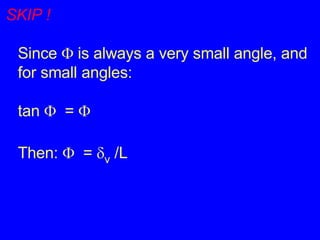
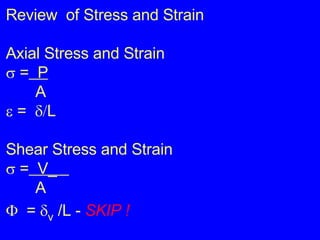
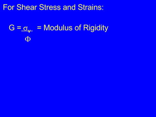
1) Definitions of stress as force per unit area and strain as deformation per original length. Common types of stress include axial/tensile, compressive, shear, and bearing stresses.
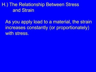
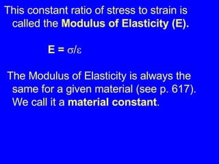
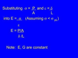
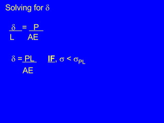
2) The proportional relationship between stress and strain for a material below its proportional limit, defined by modulus of elasticity E. Stress and strain can then be calculated from each other.
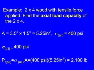
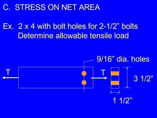
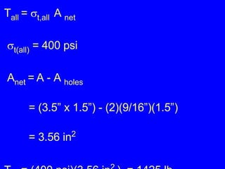
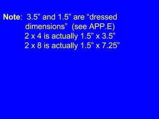
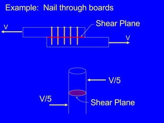
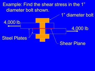
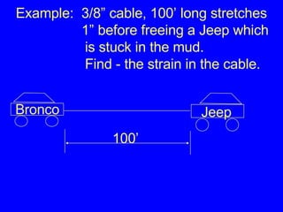
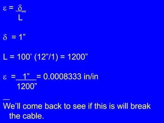
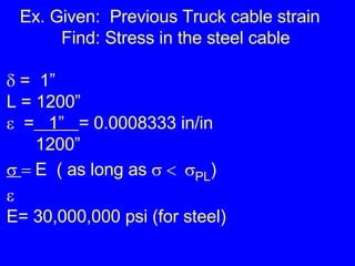
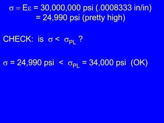
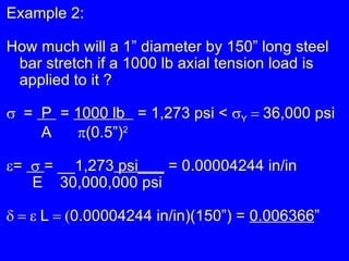
3) Examples calculating stresses, strains, and deformations in axially loaded members and bolts, finding required member sizes, and checking stresses are below limits.


![01 01 chapgere[1]](https://cdn.slidesharecdn.com/ss_thumbnails/01-01chapgere1-130611230425-phpapp02-thumbnail.jpg?width=640&height=640&fit=bounds)