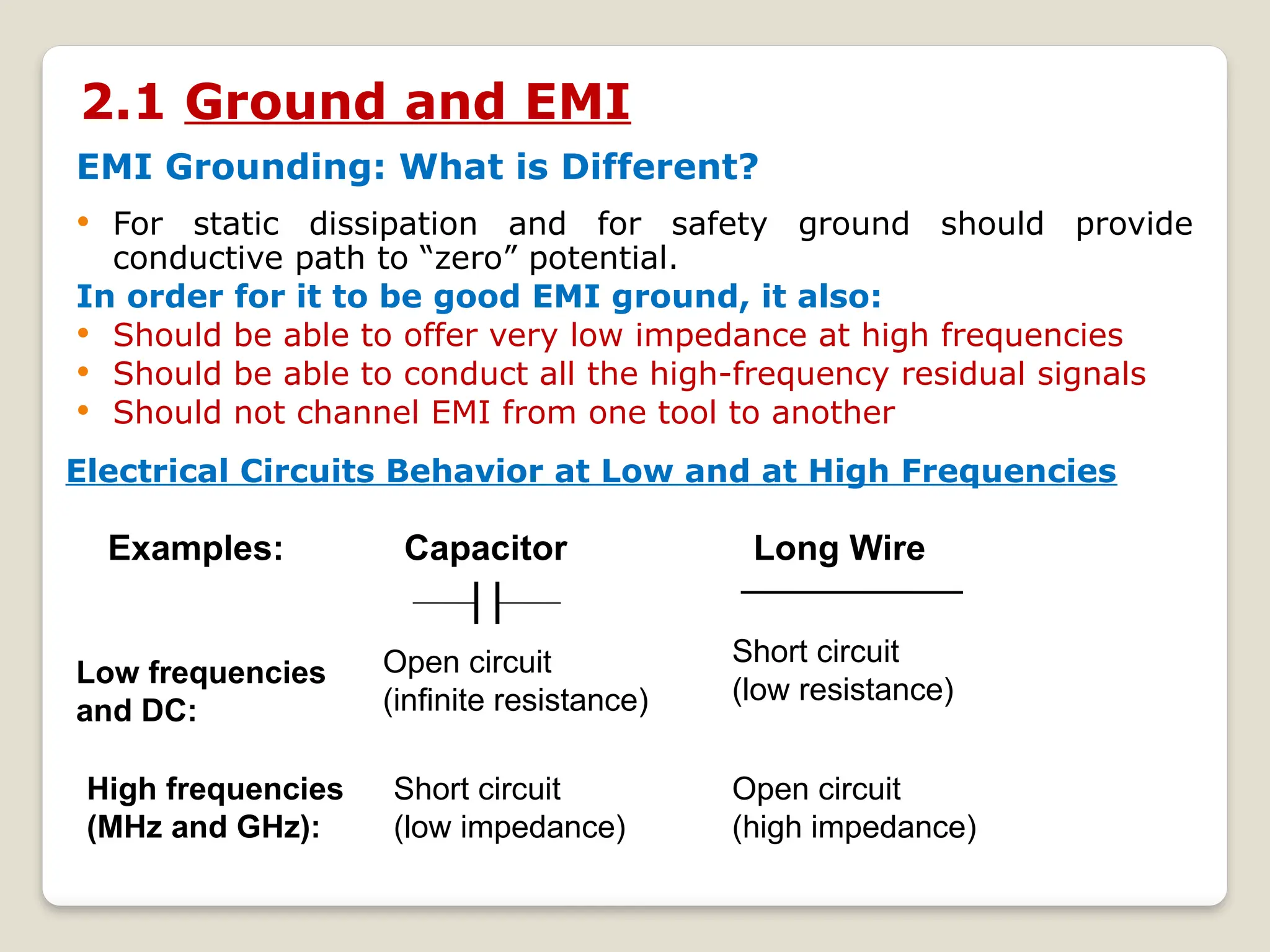
Chapter -2
EMI Mitigation Techniques
Bewnet Getachew
Gollis University
Contents_____________________________________
2.1 Grounding
2.2 Cabling
2.3 Balancing and Filtering
2.4 Passive Components
2.5 Shielding
2.6 Contact Protection
2.7 Intrinsic Noise Sources
2.8 Active Device Noise
2.9 Digital Circuit Grounding
Introduction
 The immunity level of each device is such that it is not disturbed
by its electromagnetic environment.
Its interference emission level must be low enough not to
interfere with devices located in its electromagnetic environment.
Example of ‘layered’ EM mitigation (using
shielding and filtering)
What is current management?
2.1 Ground and EMI
EMI Grounding: What is Different?
 For static dissipation and for safety ground should provide
conductive path to “zero” potential.
In order for it to be good EMI ground, it also:
 Should be able to offer very low impedance at high frequencies
 Should be able to conduct all the high-frequency residual signals
 Should not channel EMI from one tool to another
Electrical Circuits Behavior at Low and at High Frequencies
Examples: Capacitor Long Wire
Low frequencies
and DC:
High frequencies
(MHz and GHz):
Open circuit
(infinite resistance)
Short circuit
(low impedance)
Short circuit
(low resistance)
Open circuit
(high impedance)
Grounding is one of the primary ways of minimizing unwanted
noise and of producing a safe system.
It is the responsibility of the designer to provide both a safe
and a noise-free system.
One advantage of a well-designed ground system is that it can often
provide protection against unwanted interference and emission,
without any additional per-unit cost to the product.
In comparison, an improperly designed ground system may be a
primary source of interference and emission and therefore require
considerable engineering time to eliminate the problem. Hence, a
properly designed ground system can be truly cost effective.
Grounds fall into two categories as follows:
(1) safety grounds and
(2) signal grounds
(1) safety grounds
In most cases, safety grounds do not carry current, except during a
fault.
In addition, if a ground is connected to the enclosure or chassis of the
equipment, then it is often called a chassis ground.
If a ground is connected to the earth through a low-impedance path,
then it may be called an earth ground.
Safety grounds are usually connected to the earth or some
conducting body that serves in place of the earth such as the
airframe of an aircraft or the hull of a ship.
(2) signal grounds (Returns)
Signal grounds do carry current during normal operation.
Three basic objectives of signal grounding are as follows:
1. Not to interrupt the ground return path
2. Return the current through the smallest loop possible
3. Be aware of possible common impedance coupling in the ground
A better definition for a signal ground is a low-impedance path for
current to return to the source.
Controlling differential mode coupling
The proper signal ground system is determined by many things, such
as the
Type of circuitry
The frequency of operation
The size of the system, whether it is self-contained or
distributed, safety and
Electrostatic discharge (ESD) protection.
All ground systems have advantages as well as disadvantages. The
designer’s job is to maximize the advantages and to minimize the
disadvantages of the ground for the application at hand.
Ground Noise voltage(Vg) = IgZg
There are two ways to minimize the ground noise voltage Vg.
1. Minimize the ground impedance Zg.
2. Decrease Ig by forcing the ground current to flow
through a different path.
The first approach is commonly used at high frequency and with digital
circuits, by using a ground plane or grid. The latter approach is
commonly used with low-frequency analog circuits.
Zg = Rg + jωLg
The most important characteristic of
a ground conductor is its impedance.
clearly shows the effect that
frequency has on ground impedance.
At low frequency, the resistance Rg
will be dominant. At high frequency,
the inductance Lg will be the
dominant impedance.
FIGURE 2-2. A double-sided
PCB with a single trace on the
topside and a full ground
plane on the bottom side.
How does the ground plane
current flow between points A
and B?
FIGURE 2-3. Ground plane current path, (A) at low frequency the
return current takes the path of least resistance and (B), at high
frequency the return current takes the path of least inductance.
At low frequencies, the ground current will take the path of least
resistance, which is directly between points A and B as shown in Fig.
2-3A. However, at high frequencies, the ground current takes the path
of least inductance, which is directly under the trace.
Signal grounds can be divided into the following three categories:
1. Single-point grounds
2. Multipoint grounds
3. Hybrid grounds
1. Single-Point Ground Systems
Single-point grounds are most effectively used at low frequency, from
dc up to about 20 kHz. They should usually not be used above 100
kHz.
FIGURE 2-4. Two types of single-point grounding connections
FIGURE 2-5. Common, or daisy chain, single-point ground system is a series
ground connection and is undesirable from a noise standpoint, but it has the
advantage of simple wiring.
FIGURE 2-6. Separate, or parallel, single-point ground system is a parallel
ground connection and provides good low-frequency grounding, but it may be
mechanically cumbersome in large systems.
FIGURE 2-7. A single-point series-parallel
grounding.
2. Multipoint Ground Systems
At high frequency, there is no such thing as a single-point ground.
Because of their inductance, the ground conductors represent high
impedances. However at high frequency, the impedance of the stray
capacitance between the circuits and ground is low. The ground
current therefore flows through the low impedance of the stray
capacitance and not the high impedance that results from the
inductance of the long ground conductors. The result is a multipoint
ground at high frequency.
FIGURE 2-8. At high
frequency, single-point
grounds become multipoint
grounds because of stray
capacitance.
Multipoint grounds are used at high frequency (above 100 kHz) and in
digital circuitry. Multipoint ground systems minimize the ground noise
voltage Vg by minimizing the ground impedance Zg.
Zg = Rg + jωLg
we observe that at high frequency, this means minimizing the ground
inductance, which can be done by the use of ground planes or grids.
Where possible, use multiple connections between the circuits and
the plane to reduce the inductance.
FIGURE 2-9. Multipoint
ground system is a good
choice at frequencies
above about 100 kHz.
Impedances R1–R3 and L1
– L3 must be minimized at
the frequency of interest.
The low ground impedance is primarily the result of the low
inductance of the ground plane. The connections between each circuit
and the ground plane should be kept as short as possible to minimize
their impedance. In many high-frequency circuits, the length of these
ground leads may have to be kept to a small fraction of an inch.
3. Hybrid Grounds
When the signal frequency covers a wide range both above and
below 100 kHz, a hybrid ground may be a solution. A video signal is
a good example of this; the signal frequencies can range from 30 Hz
to tens of megahertz. A hybrid ground is one in which the system-
grounding configuration behaves differently at different frequencies.
FIGURE 2-10. A hybrid
ground connection that
acts as a single-point
ground at low
frequencies and a
multipoint ground at high
frequencies.
A practical application of this principle is the cable-shielding
configuration shown in Fig. 2-11. At low frequency, the capacitor C is
a high impedance and the cable shield is single-point grounded at the
load end only. At high frequency, the capacitor C is a low impedance
and the cable shield is effectively grounded at both ends.
FIGURE 2-11. Example of a hybrid grounded cable shield.
Single-point vs. multi-point grounds
2.2 Cabling
Cables are important because they are usually the longest parts of a
system and therefore act as efficient antennas that pick up and/or
radiate noise.
Controlling differential mode coupling
COAXIAL CABLE VERSUS TWISTED PAIR
FIGURE 2-10. Useful frequency range for various transmission lines.
Normal applications (solid line) and special applications (dashed line).
A Comparison of Common Transmission
Lines and Waveguides
Comparison ofTransmission lines
The factors to be considered in comparing transmission lines are:
 Frequency range
Bandwidth
Power handling capability
Attenuation and Interference.
Size
Ease of fabrication
Flexibility
1. Referring the figure shown below, which transmission line is
much suitable to connect a Wi-fi transmitter of 100w and working
frequency of 2.4 GHz with antenna?
2. Referring the figure shown below, which transmission line is
much suitable to connect a Radar transmitter of 100Kw and
working frequency of 10GHz with antenna?
3. Referring the figure shown below, which transmission line is
much suitable to connect a microwave transmitter of 500w
power and working frequency of 1 GHz with microwave
antenna?
Twisted pair cables
None uniform characteristic impedance. Bonded twisted pair
cables provide a more uniform characteristic impedance and are
more immune to noise and produce much less radiation.
The normal useful frequency for twisted pair cables was considered
to be about 100 kHz. Today’s cable designers have been able to
extend the normal useful frequency of twisted pairs up to 10 MHz
with some applications [e.g., Ethernet and high-definition multimedia
interface (HDMI)] extending up to hundreds of megahertz. These
high performance cables have less capacitance and are more tightly
and uniformly twisted.
Many modern-day unshielded twisted pair (UTP) cables perform as
well or better than older shielded twisted pair (STP) cables. A
twisted pair cable is inherently a balanced structure and effectively
rejects noise.
Excellent examples of this are category (Cat) 5 and Cat 6
Ethernet cables.
FIGURE 2-11. Cat 5
Ethernet cable which consists
of four UTPs made from 24-
gauge solid wire
Cat 5e UTP cables are
designed to perform well up
to 125 MHz, Cat 6 cables up
to 250MHz, and in the
future, Cat 7 cables should
be useful up to about 600
MHz.
The signal current flows in the two inner conductors, and any induced
noise current flows in the shield. Common impedance coupling is
therefore eliminated.
In addition, any shield current present is equally coupled (ideally), by
mutual inductance, to both inner conductors and the two equal noise
voltages cancel.
An unshielded twisted pair, unless its terminations are balanced
provides very little protection against capacitive (electric field) pickup,
but it is very good for protection against magnetic field pickup.
The effectiveness of twisting increases as the number of twists per
unit length increases.
When terminating a twisted pair, the more the two wires are
separated, the less the noise suppression. Therefore, when
terminating a twisted pair, shielded or unshielded, do not untwist the
conductors any more than necessary to make the termination.
Twisted pair cables, even when unshielded, are very effective in
reducing magnetic field coupling. Only two conditions are necessary
for this to be true.
First, the signal must flow equally and in opposite directions on the
two conductors.
Second, the pitch of the twist must be less than one twentieth of a
wavelength at the frequencies of concern.
Coaxial cables
Coaxial cable has a more uniform characteristic impedance with
lower losses.
It is useful from dc up to very high frequency (VHF), with some
applications extending up to ultra high frequency (UHF). Above 1
GHz, the losses in coaxial cable become large, and a waveguide
often becomes a more practical transmission medium.
A coaxial cable grounded at one end provides a good degree of
protection from capacitive (electric field) pickup. But if a noise
current flows in the shield, then a noise voltage is produced.
A double-shielded, or triaxial, cable with insulation between the two
shields can eliminate the noise voltage produced by the shield
resistance.
Unfortunately, triaxial cables are expensive and awkward to use. A
coaxial cable at high frequencies, however, acts as a triaxial cable
because of skin effect. For a typical coaxial cable, the skin effect
becomes important at about 1 MHz. The noise current flows on the
outside surface of the shield, whereas the signal current flows on
the inside surface. For this reason, a coaxial cable behaves better at
high frequency.
BRAIDED SHIELDS
Most cables are actually shielded with braid rather than with a solid
conductor.
The advantage of braid is flexibility, durability, strength, and long
flex life.
FIGURE 2-12. Cable with a braid
shield.
Braids typically provide only 60%
to 98% coverage and are less
effective as shields than solid
conductors.
A braid is typically from 5 to 30 dB
less effective than a solid shield for
protecting against magnetic fields.
SPIRAL SHIELDS
FIGURE 2-14. Cable with a spiral
shield.
SHIELD TERMINATIONS
Most shielded cable problems are the result of improper shield
terminations. The maximum benefit of a well-shielded cable will only
be realized if the shield is properly terminated. Requirements of a
proper shield termination are as follows:
1. Termination at the proper end, or ends, and to the proper
point or points.
2. A very low impedance termination connection.
3. A 3600
contact with the shield.
Pigtails FIGURE 2-15. Pigtail shield
connection concentrates current on
one side of the shield.
For maximum protection, the shield
should be terminated uniformly
around its circumference. This can be
accomplished by using coaxial
connectors such as BNC, UHF, or Type
N.
FIGURE 2-16.
Disassembled BNC
connector showing a 3600
contact to the shield.
FIGURE 2-17. A female XLR
connector (used in pro-audio
installations) with spring
fingers around its
circumference to provide a
3600
contact between mating
halves of the connector back
shell.
Grounding of Cable Shields
The most common questions asked with respect to cable shield
grounding are, where should the shield be terminated? At one end or
at both ends and to what should it be connected? The simple answer is
that it depends!
Low-Frequency Cable Shield Grounding
The main reason to shield cables at low frequency is to protect them
against electric field coupling primarily from 50/60-Hz power
conductors. A shield provides no magnetic field protection at low
frequency. This points out the advantage of using shielded twisted pair
cables at low frequency:
The shield protects against the electric field coupling and the twisted
pair protects against the magnetic field coupling. Many low-frequency
circuits contain high-impedance devices that are susceptible to electric
field coupling, hence, the importance of low-frequency cable shielding.
At low frequency, shields on multi conductor cables where the shield
is not the signal return conductor are often grounded at only one
end.
Usually, it is better to ground the shield at the source end, because
that is the reference for the signal voltage. If the signal source is
floating (not grounded), however, then it is better to ground the
cable shield at the load end.
FIGURE 2-17. Preferred low-frequency shield grounding schemes for
shielded twisted pair and coaxial cables.
The single-ended shield ground is effective at low frequencies (audio
and below), because it prevents power-frequency currents from
flowing on the shield and possibly introducing noise into the signal
circuit. The single-point ground also eliminates the shield ground loop
and its associated possible magnetic field pickup. As frequency
increases, however, the single-point ground becomes less and less
effective. As the cable length approaches one-quarter wavelength, a
cable shield grounded at one end becomes a very efficient antenna.
Under these circumstances, grounding both ends of the shield is
normally required.
High-Frequency Cable Shield Grounding.
FIGURE 2-18. At
high frequencies, stay
capacitance completes
the ground loop.
At frequencies above about 100 kHz, or where cable length exceeds
one twentieth of a wavelength, it becomes necessary to ground the
shield at both ends. This is true for either Multi-conductor or coaxial
cables.
It is therefore common practice at high frequency, and with digital
circuits, to ground the cable shield at both ends.
July 11, 2006 STEP7
3
2.3 Electromagnetic Shielding
Shielding theory: reflection
Fix-Its – RF Enclosures & Shielding
RF Cabinet
Copper Tape
Knitted Mesh
2.4 Balancing and Filtering

chapter 2 EMI Mitigation techniques.pptx

  • 1.
    Chapter -2 EMI MitigationTechniques Bewnet Getachew Gollis University
  • 2.
    Contents_____________________________________ 2.1 Grounding 2.2 Cabling 2.3Balancing and Filtering 2.4 Passive Components 2.5 Shielding 2.6 Contact Protection 2.7 Intrinsic Noise Sources 2.8 Active Device Noise 2.9 Digital Circuit Grounding
  • 3.
    Introduction  The immunitylevel of each device is such that it is not disturbed by its electromagnetic environment. Its interference emission level must be low enough not to interfere with devices located in its electromagnetic environment.
  • 4.
    Example of ‘layered’EM mitigation (using shielding and filtering)
  • 5.
    What is currentmanagement?
  • 6.
    2.1 Ground andEMI EMI Grounding: What is Different?  For static dissipation and for safety ground should provide conductive path to “zero” potential. In order for it to be good EMI ground, it also:  Should be able to offer very low impedance at high frequencies  Should be able to conduct all the high-frequency residual signals  Should not channel EMI from one tool to another Electrical Circuits Behavior at Low and at High Frequencies Examples: Capacitor Long Wire Low frequencies and DC: High frequencies (MHz and GHz): Open circuit (infinite resistance) Short circuit (low impedance) Short circuit (low resistance) Open circuit (high impedance)
  • 7.
    Grounding is oneof the primary ways of minimizing unwanted noise and of producing a safe system. It is the responsibility of the designer to provide both a safe and a noise-free system. One advantage of a well-designed ground system is that it can often provide protection against unwanted interference and emission, without any additional per-unit cost to the product. In comparison, an improperly designed ground system may be a primary source of interference and emission and therefore require considerable engineering time to eliminate the problem. Hence, a properly designed ground system can be truly cost effective. Grounds fall into two categories as follows: (1) safety grounds and (2) signal grounds
  • 8.
    (1) safety grounds Inmost cases, safety grounds do not carry current, except during a fault. In addition, if a ground is connected to the enclosure or chassis of the equipment, then it is often called a chassis ground. If a ground is connected to the earth through a low-impedance path, then it may be called an earth ground. Safety grounds are usually connected to the earth or some conducting body that serves in place of the earth such as the airframe of an aircraft or the hull of a ship. (2) signal grounds (Returns) Signal grounds do carry current during normal operation. Three basic objectives of signal grounding are as follows: 1. Not to interrupt the ground return path 2. Return the current through the smallest loop possible 3. Be aware of possible common impedance coupling in the ground A better definition for a signal ground is a low-impedance path for current to return to the source.
  • 9.
  • 10.
    The proper signalground system is determined by many things, such as the Type of circuitry The frequency of operation The size of the system, whether it is self-contained or distributed, safety and Electrostatic discharge (ESD) protection. All ground systems have advantages as well as disadvantages. The designer’s job is to maximize the advantages and to minimize the disadvantages of the ground for the application at hand. Ground Noise voltage(Vg) = IgZg There are two ways to minimize the ground noise voltage Vg. 1. Minimize the ground impedance Zg. 2. Decrease Ig by forcing the ground current to flow through a different path. The first approach is commonly used at high frequency and with digital circuits, by using a ground plane or grid. The latter approach is commonly used with low-frequency analog circuits.
  • 11.
    Zg = Rg+ jωLg The most important characteristic of a ground conductor is its impedance. clearly shows the effect that frequency has on ground impedance. At low frequency, the resistance Rg will be dominant. At high frequency, the inductance Lg will be the dominant impedance. FIGURE 2-2. A double-sided PCB with a single trace on the topside and a full ground plane on the bottom side. How does the ground plane current flow between points A and B?
  • 12.
    FIGURE 2-3. Groundplane current path, (A) at low frequency the return current takes the path of least resistance and (B), at high frequency the return current takes the path of least inductance. At low frequencies, the ground current will take the path of least resistance, which is directly between points A and B as shown in Fig. 2-3A. However, at high frequencies, the ground current takes the path of least inductance, which is directly under the trace.
  • 13.
    Signal grounds canbe divided into the following three categories: 1. Single-point grounds 2. Multipoint grounds 3. Hybrid grounds 1. Single-Point Ground Systems Single-point grounds are most effectively used at low frequency, from dc up to about 20 kHz. They should usually not be used above 100 kHz. FIGURE 2-4. Two types of single-point grounding connections
  • 14.
    FIGURE 2-5. Common,or daisy chain, single-point ground system is a series ground connection and is undesirable from a noise standpoint, but it has the advantage of simple wiring. FIGURE 2-6. Separate, or parallel, single-point ground system is a parallel ground connection and provides good low-frequency grounding, but it may be mechanically cumbersome in large systems.
  • 15.
    FIGURE 2-7. Asingle-point series-parallel grounding.
  • 16.
    2. Multipoint GroundSystems At high frequency, there is no such thing as a single-point ground. Because of their inductance, the ground conductors represent high impedances. However at high frequency, the impedance of the stray capacitance between the circuits and ground is low. The ground current therefore flows through the low impedance of the stray capacitance and not the high impedance that results from the inductance of the long ground conductors. The result is a multipoint ground at high frequency. FIGURE 2-8. At high frequency, single-point grounds become multipoint grounds because of stray capacitance.
  • 17.
    Multipoint grounds areused at high frequency (above 100 kHz) and in digital circuitry. Multipoint ground systems minimize the ground noise voltage Vg by minimizing the ground impedance Zg. Zg = Rg + jωLg we observe that at high frequency, this means minimizing the ground inductance, which can be done by the use of ground planes or grids. Where possible, use multiple connections between the circuits and the plane to reduce the inductance. FIGURE 2-9. Multipoint ground system is a good choice at frequencies above about 100 kHz. Impedances R1–R3 and L1 – L3 must be minimized at the frequency of interest.
  • 18.
    The low groundimpedance is primarily the result of the low inductance of the ground plane. The connections between each circuit and the ground plane should be kept as short as possible to minimize their impedance. In many high-frequency circuits, the length of these ground leads may have to be kept to a small fraction of an inch. 3. Hybrid Grounds When the signal frequency covers a wide range both above and below 100 kHz, a hybrid ground may be a solution. A video signal is a good example of this; the signal frequencies can range from 30 Hz to tens of megahertz. A hybrid ground is one in which the system- grounding configuration behaves differently at different frequencies. FIGURE 2-10. A hybrid ground connection that acts as a single-point ground at low frequencies and a multipoint ground at high frequencies.
  • 19.
    A practical applicationof this principle is the cable-shielding configuration shown in Fig. 2-11. At low frequency, the capacitor C is a high impedance and the cable shield is single-point grounded at the load end only. At high frequency, the capacitor C is a low impedance and the cable shield is effectively grounded at both ends. FIGURE 2-11. Example of a hybrid grounded cable shield.
  • 20.
  • 21.
    2.2 Cabling Cables areimportant because they are usually the longest parts of a system and therefore act as efficient antennas that pick up and/or radiate noise. Controlling differential mode coupling
  • 22.
    COAXIAL CABLE VERSUSTWISTED PAIR FIGURE 2-10. Useful frequency range for various transmission lines. Normal applications (solid line) and special applications (dashed line).
  • 23.
    A Comparison ofCommon Transmission Lines and Waveguides Comparison ofTransmission lines The factors to be considered in comparing transmission lines are:  Frequency range Bandwidth Power handling capability Attenuation and Interference. Size Ease of fabrication Flexibility
  • 24.
    1. Referring thefigure shown below, which transmission line is much suitable to connect a Wi-fi transmitter of 100w and working frequency of 2.4 GHz with antenna? 2. Referring the figure shown below, which transmission line is much suitable to connect a Radar transmitter of 100Kw and working frequency of 10GHz with antenna? 3. Referring the figure shown below, which transmission line is much suitable to connect a microwave transmitter of 500w power and working frequency of 1 GHz with microwave antenna?
  • 26.
    Twisted pair cables Noneuniform characteristic impedance. Bonded twisted pair cables provide a more uniform characteristic impedance and are more immune to noise and produce much less radiation. The normal useful frequency for twisted pair cables was considered to be about 100 kHz. Today’s cable designers have been able to extend the normal useful frequency of twisted pairs up to 10 MHz with some applications [e.g., Ethernet and high-definition multimedia interface (HDMI)] extending up to hundreds of megahertz. These high performance cables have less capacitance and are more tightly and uniformly twisted. Many modern-day unshielded twisted pair (UTP) cables perform as well or better than older shielded twisted pair (STP) cables. A twisted pair cable is inherently a balanced structure and effectively rejects noise. Excellent examples of this are category (Cat) 5 and Cat 6 Ethernet cables.
  • 27.
    FIGURE 2-11. Cat5 Ethernet cable which consists of four UTPs made from 24- gauge solid wire Cat 5e UTP cables are designed to perform well up to 125 MHz, Cat 6 cables up to 250MHz, and in the future, Cat 7 cables should be useful up to about 600 MHz. The signal current flows in the two inner conductors, and any induced noise current flows in the shield. Common impedance coupling is therefore eliminated. In addition, any shield current present is equally coupled (ideally), by mutual inductance, to both inner conductors and the two equal noise voltages cancel.
  • 28.
    An unshielded twistedpair, unless its terminations are balanced provides very little protection against capacitive (electric field) pickup, but it is very good for protection against magnetic field pickup. The effectiveness of twisting increases as the number of twists per unit length increases. When terminating a twisted pair, the more the two wires are separated, the less the noise suppression. Therefore, when terminating a twisted pair, shielded or unshielded, do not untwist the conductors any more than necessary to make the termination. Twisted pair cables, even when unshielded, are very effective in reducing magnetic field coupling. Only two conditions are necessary for this to be true. First, the signal must flow equally and in opposite directions on the two conductors. Second, the pitch of the twist must be less than one twentieth of a wavelength at the frequencies of concern.
  • 29.
    Coaxial cables Coaxial cablehas a more uniform characteristic impedance with lower losses. It is useful from dc up to very high frequency (VHF), with some applications extending up to ultra high frequency (UHF). Above 1 GHz, the losses in coaxial cable become large, and a waveguide often becomes a more practical transmission medium. A coaxial cable grounded at one end provides a good degree of protection from capacitive (electric field) pickup. But if a noise current flows in the shield, then a noise voltage is produced. A double-shielded, or triaxial, cable with insulation between the two shields can eliminate the noise voltage produced by the shield resistance. Unfortunately, triaxial cables are expensive and awkward to use. A coaxial cable at high frequencies, however, acts as a triaxial cable because of skin effect. For a typical coaxial cable, the skin effect becomes important at about 1 MHz. The noise current flows on the outside surface of the shield, whereas the signal current flows on the inside surface. For this reason, a coaxial cable behaves better at high frequency.
  • 30.
    BRAIDED SHIELDS Most cablesare actually shielded with braid rather than with a solid conductor. The advantage of braid is flexibility, durability, strength, and long flex life. FIGURE 2-12. Cable with a braid shield. Braids typically provide only 60% to 98% coverage and are less effective as shields than solid conductors. A braid is typically from 5 to 30 dB less effective than a solid shield for protecting against magnetic fields.
  • 32.
    SPIRAL SHIELDS FIGURE 2-14.Cable with a spiral shield. SHIELD TERMINATIONS Most shielded cable problems are the result of improper shield terminations. The maximum benefit of a well-shielded cable will only be realized if the shield is properly terminated. Requirements of a proper shield termination are as follows: 1. Termination at the proper end, or ends, and to the proper point or points. 2. A very low impedance termination connection. 3. A 3600 contact with the shield.
  • 33.
    Pigtails FIGURE 2-15.Pigtail shield connection concentrates current on one side of the shield. For maximum protection, the shield should be terminated uniformly around its circumference. This can be accomplished by using coaxial connectors such as BNC, UHF, or Type N. FIGURE 2-16. Disassembled BNC connector showing a 3600 contact to the shield.
  • 34.
    FIGURE 2-17. Afemale XLR connector (used in pro-audio installations) with spring fingers around its circumference to provide a 3600 contact between mating halves of the connector back shell. Grounding of Cable Shields The most common questions asked with respect to cable shield grounding are, where should the shield be terminated? At one end or at both ends and to what should it be connected? The simple answer is that it depends!
  • 35.
    Low-Frequency Cable ShieldGrounding The main reason to shield cables at low frequency is to protect them against electric field coupling primarily from 50/60-Hz power conductors. A shield provides no magnetic field protection at low frequency. This points out the advantage of using shielded twisted pair cables at low frequency: The shield protects against the electric field coupling and the twisted pair protects against the magnetic field coupling. Many low-frequency circuits contain high-impedance devices that are susceptible to electric field coupling, hence, the importance of low-frequency cable shielding. At low frequency, shields on multi conductor cables where the shield is not the signal return conductor are often grounded at only one end. Usually, it is better to ground the shield at the source end, because that is the reference for the signal voltage. If the signal source is floating (not grounded), however, then it is better to ground the cable shield at the load end.
  • 36.
    FIGURE 2-17. Preferredlow-frequency shield grounding schemes for shielded twisted pair and coaxial cables.
  • 37.
    The single-ended shieldground is effective at low frequencies (audio and below), because it prevents power-frequency currents from flowing on the shield and possibly introducing noise into the signal circuit. The single-point ground also eliminates the shield ground loop and its associated possible magnetic field pickup. As frequency increases, however, the single-point ground becomes less and less effective. As the cable length approaches one-quarter wavelength, a cable shield grounded at one end becomes a very efficient antenna. Under these circumstances, grounding both ends of the shield is normally required. High-Frequency Cable Shield Grounding. FIGURE 2-18. At high frequencies, stay capacitance completes the ground loop.
  • 38.
    At frequencies aboveabout 100 kHz, or where cable length exceeds one twentieth of a wavelength, it becomes necessary to ground the shield at both ends. This is true for either Multi-conductor or coaxial cables. It is therefore common practice at high frequency, and with digital circuits, to ground the cable shield at both ends.
  • 39.
    July 11, 2006STEP7 3 2.3 Electromagnetic Shielding Shielding theory: reflection
  • 40.
    Fix-Its – RFEnclosures & Shielding RF Cabinet Copper Tape Knitted Mesh
  • 41.