Downloaded 1,696 times

![T1=450
T2=300
T3=200
T5=100
T4=135
T6=85
T2A=280
T2B=260
T2C=230
T2D=215
T3A=180
T3B=165
T3C=160
T4C=120
ºC
T1=450
T2=300
T3=200
T5=100
T4=135
T6=85
ºC
PHoENIx CoNTACT 17
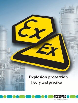
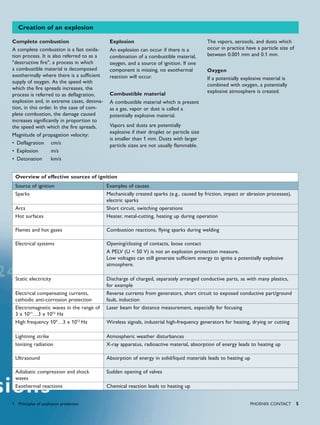
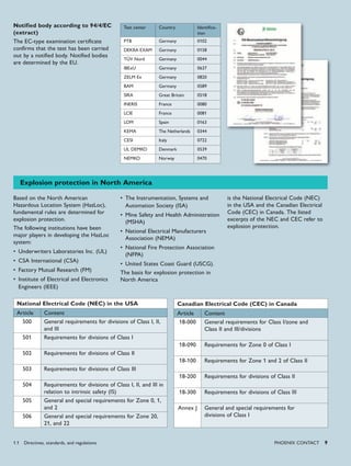
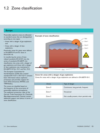
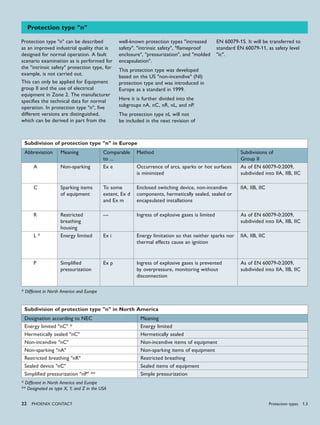
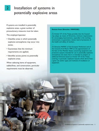
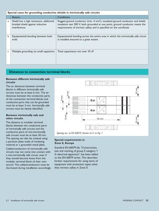
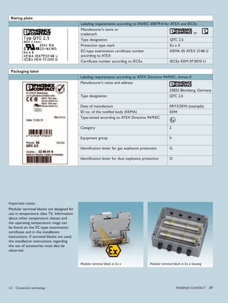
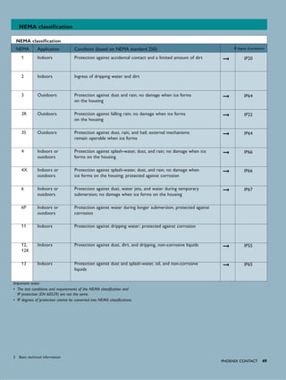
Group II temperature classes
for Europe and the USA
Permissible surface temperature
for gases
Ignition temperature of the gas
Ammonia 630°C
Methane 595°C
Hydrogen 560°C
Propane 470°C
Ethylene 425°C
Butane 365°C
Acetylene 305°C
Cyclohexane 259°C
Diethyl ether 170°C
Carbon disulfide 95°C
Group II
Temperatures for Group I
Group I Temperature Conditions
Mines susceptible to fire-
damp (coal mining)
150°C
With deposits of coal dust
on the item of equipment
450°C
Without deposits of coal dust
on the item of equipment
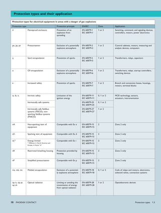
Temperature limits with dust
In the case of areas with a danger of
dust explosions, the maximum surface
temperature is given as a temperature
value [°C].
The maximum surface temperature of
the item of equipment must not exceed
the ignition temperature of a layer of
dust or a cloud of combustible dust.
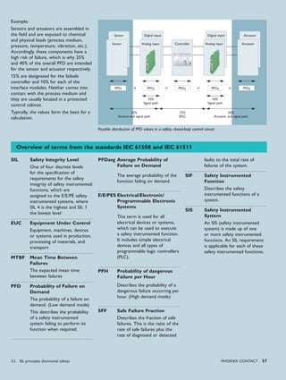
Example
Modular terminal blocks are used in a
housing of protection type Ex e IIC T6.
In this case, the maximum permissible
amperage must be calculated so that
the temperature class T6 is also
maintained at the modular terminal
blocks. The housing is designed with
IP degree of protection IP54, but
Air distances
Creepage distances
Air and creepage distance
the potentially explosive gas can still
penetrate the housing. For this reason,
it is not sufficient only to consider the
surface temperature of the housing.
Air and creepage distance
Air and creepage distances must be
maintained for the "intrinsic safety",
"increased safety", and "n" protection
types.
The term "air distance" is defined as
the shortest connection between two
potentials through the air. The "creepage
distance" is the shortest connection
between two potentials over a surface.
A minimum distance must be maintained,
depending on the comparative tracking
index (CTI) of the material.
The minimum air and creepage distances
to be applied are specified in the
corresponding protection type.
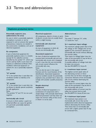
Temperature classes/limits for
gases and dusts
Temperatures for Group I
The maximum permissible surface
temperature of the item of equipment
depends on the type of coal dust
deposit.
Temperature classes for Group II
The potentially explosive atmosphere
can be prevented from igniting if the
surface temperature of the item of
equipment is lower than the ignition
temperature of the surrounding gas.
The surface temperature is valid for all
parts of an item of electrical equipment
that can come into contact with the
potentially explosive material.
The majority of the gases can be
assigned to the temperature classes T1
to T3.
Reference: GESTIS Substance Database
1.3 Protection types
Housing Ex e with
modular terminal blocks](https://image.slidesharecdn.com/explosionprotection-theoryandpractice-140424155213-phpapp01/85/Explosion-protection-theory-and-practice-17-320.jpg)
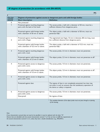
![26 PHoENIx CoNTACT
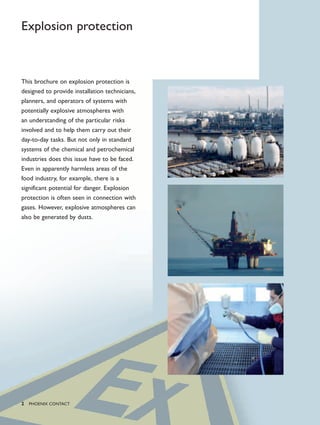
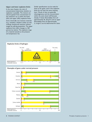
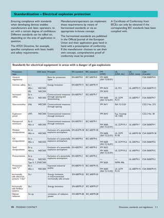
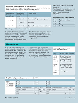
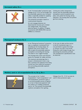
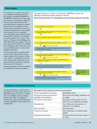
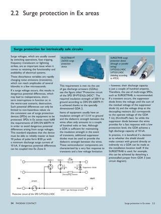
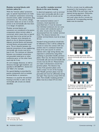
In Europe, the labeling of items of equipment, components, and protection systems is based on the labeling laid down in directives and standards.
Labeling according to ATEX Directive 94/9/EC
Examples of labeling according to ATEX Directive 94/9/EC and EN 60079-0
Gas - Ex Number of the
EC-type examination
certificate/declaration
of conformity
U: component
X: special installation conditions
Mark
... according to ATEX … according
to standard
EN 60079-0:2006
… according to
standard
EN 60079-0:2009
… according
to standard
EN 60079-0:2009,
alternative
Electrical
equipment
IBExU 09 ATEX 1030 CE II 3 G Ex nA II T4 Ex nA IIC T4 Gc Ex nAc IIC T4
Item of
associated
electrical
equipment
BVS 08 ATEX E 094 X CE 0344 II (1) G [Ex ia] IIC [Ex ia Ga] IIC [Ex ia] IIC
Component KEMA 07 ATEX 0193 U 0344 II 2 G Ex e II Ex e IIC Gb Ex eb IIC
Examples of labeling according to EN 61241-0 or EN 60079-0
Dust - Ex Number of the
EC-type examination
certificate/declaration
of conformity
U: component
X: special installation conditions
Mark
… according to standard
EN 61241:2006
… according to standard
EN 60079-0:2009
… according to standard
EN 60079-0:2009,
alternative
Electrical
equipment
PTB 00 ATEX 0000 X Ex tD A21 IP65 T80°C Ex tb IIIC T80°C Db Ex tb IIIC T80°C
Item of
associated
electrical
equipment
TÜV 00 ATEX 0000 [Ex iaD] [Ex ia Da] IIIC [Ex ia] IIIC
X
X
X
Equipment cate-
gory according to
ATEX Directive
94/9/EC
EPL (Equipment
Protection Level)
Zone Type of danger
Gas 1G Ga 0 Continuous, long
periods, frequent
2G Gb 1 Occasional
3G Gc 2 Not usually present,
short periods only
Dust 1D Da 20 Continuous, long
periods, frequent
2D Db 21 Occasional
3D Dc 22 Not usually present,
short periods only
Min-
ing
M1 Ma Continuous, long
periods, frequent
M2 Mb Occasional
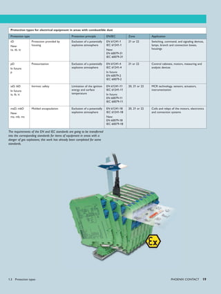
Relationship between categories,
EPL, and zones
The equipment protection level (EPL) is
a new addition to the EN 60079-0:2009
standard and specifies the equipment
protection level of the device or
component. The equipment protection
level should be viewed in the same way
as the categories used in the ATEX
Directive. This now provides a way of
assigning devices to zones that is simpler
than labeling them according to their
protection type.
Labeling of Ex products 1.4](https://image.slidesharecdn.com/explosionprotection-theoryandpractice-140424155213-phpapp01/85/Explosion-protection-theory-and-practice-26-320.jpg)
![➞
➞
➞
➞
➞
➞
➞
PHoENIx CoNTACT 27
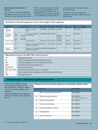
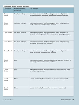
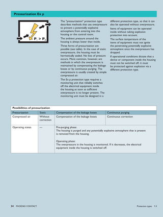
Labeling according to IECEx
With the IECEx system, labeling is purely derived from the requirements of the IEC standards.
Examples of labeling according to IEC 61241-0 or 60079-0
Dust - Ex Number of the
IECEx Certificate of
Conformity
U: component
X: special installation conditions
Mark
…according to standard
IEC 61241-0:2005
…according to standard
IEC 60079-0:2007
…according to standard
IEC 60079-0:2007,
alternative
Electrical
equipment
IECEx IBE 00.0000X Ex tD A21 IP65 T80°C Ex t IIIC T80°C Db Ex tb IIIC T80°C
Item of
associated
electrical
equipment
IECEx BVS 00.0000X [Ex iaD] [Ex ia Da] IIIC [Ex ia] IIIC
Examples of labeling with IECEx certificate number and according to IEC 60079-0
Gas - Ex Number of the
IECEx Certificate of
Conformity
U: component
X: special installation conditions
Mark
…according to standard
IEC 60079-0:2004
…according to standard
IEC 60079-0:2007
…according to standard
IEC 60079-0:2007,
alternative
Electrical
equipment
IECEx IBE 09.0002X Ex nA II T4 Ex nA IIC T4 Gc Ex nAc IIC T4
Item of
associated
electrical
equipment
IECEx BVS 08.035X [Ex ia] IIC [Ex ia Ga] IIC [Ex ia] IIC
Component IECEx KEM 07.0057U Ex e II Ex e IIC Gb Ex eb IIC
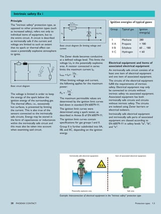
Labeling in the USA
Labeling example for an item of associated electrical equipment
Classification of the
item of equipment
1M68
Certifying body in
the USA:
in this case, UL;
c for Canada;
us for USA U
Listed CD-No: 12345678 Control drawing no. (control document)
Suitable for Class I, Div. 2, Groups A, B, C
and D installation;
Can be used
in Div 2* for
Class I: Gases
A: Acetylene
B: Hydrogen
C: Ethylene
D: Propane
providing intrinsically safe circuits for use in
Class I, Div. 1, Groups A, B, C and D; Gases
suitable for circuits
in Div 1*
* Acc. to NEC 500
Class II, Div. 1, Groups E, F and G; and Dusts
Class III, Hazardous Locations Fibers
1.4 Labeling of Ex products](https://image.slidesharecdn.com/explosionprotection-theoryandpractice-140424155213-phpapp01/85/Explosion-protection-theory-and-practice-27-320.jpg)
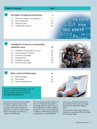
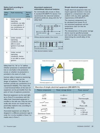
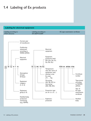
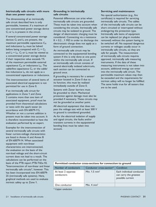
![30 PHoENIx CoNTACT
Safe area
The next step is to check the electrical
data of the intrinsically safe circuit
(voltage, current, power, capacitance,
and inductance) in accordance with the
figure below.
In the intrinsically safe circuit, all
capacitances and inductances must be
taken into account and compared with
capacitance Co and inductance Lo of the
associated equipment.
In practice, it is particularly important
to observe the capacitance, since this
can considerably restrict the length
of cables or lines. As a recommended
value, capacitance CC can be taken to
be approximately 140…200 nF/km
and inductance LC approximately
0.8…1 mH/km. Where there is any
doubt, always assume the worst case.
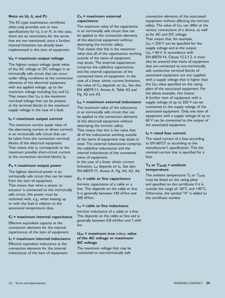
2.1 Installation of intrinsically safe
circuits
Dimensioning of intrinsically safe circuits
Installation in the "intrinsic safety"
protection type
The entire intrinsically safe circuit
must be protected against the ingress
of energy from other sources, and
against electrical and magnetic fields.
The installation technician or operator
is responsible for providing proof of
intrinsic safety, not the manufacturer.
Simple intrinsically safe circuits
Simple intrinsically safe circuits contain
just one power source. To aid planning
and installation, it is advisable to keep
the operating instructions and the
EC-type examination certificate(s) of
the items of equipment used to hand.
These must be referred to for the
necessary parameters. In the first step,
the criteria are checked according to
the following table.
Common designations Europe USA
For field device:
Max. input voltage
Max. input power
Max. internal capacitance
Max. internal inductance
Ui
Ii
Ci
Li
Vmax
Imax
Ci
Li
For associated equipment:
Max. output voltage
Max. output power
Max. external capacitance
Max. external inductance
Uo
Io
Co
Lo
Voc
Isc
Ca
La
For cable/line:
Cable/line capacitance
Cable/line inductance
Cc
Lc
Ccable
Lcable
Potentially explosive area PLC
4…20 mA
Dimensioning of intrinsically safe circuits with an item of associated equipment
Checking use in a potentially explosive area
Criteria Electrical
equipment
Items of associated
electrical equipment
Equipment group, field of
application
II, G, D II, G, D
Category 1, 2, 3 (1), (2), (3)
Group IIA, IIB, IIC IIA, IIB, IIC
Zone 0, 1, 2 0, 1, 2
Protection type Ex ia, Ex ib [Ex ia], [Ex ib]
Temperature class T1…T6 --
Installation of intrinsically safe circuits 2.1](https://image.slidesharecdn.com/explosionprotection-theoryandpractice-140424155213-phpapp01/85/Explosion-protection-theory-and-practice-30-320.jpg)
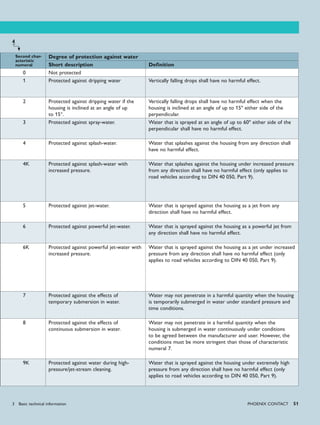
![40 PHoENIx CoNTACT
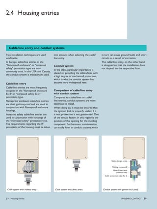
2.5 Installation examples
Installation of electrical devices for the purpose of transmitting signals
Electrical equipment operated in
systems with potentially explosive areas
is subject to different requirements,
depending on how it is used. For
example, electrical equipment could be
used in the following fields of application
if analog signals are being transmitted:
Sensors/actuators can be located in•
Zone 0, Zone 1 or Zone 2
Signal transmitters can be located in•
Zone 1, Zone 2 or the safe area
The controller, e.g., PLC, is in the safe•
area.
Examples of the installation of electrical
devices for the purpose of transmitting
signals can be found in the figure on
Page 41.
Intrinsically safe signal transmission
in potentially explosive areas
Sensors/actuators to be installed in
Zone 0 are primarily designed in the
"intrinsic safety Ex ia" protection type.
The intrinsically safe sensors/actuators
are connected to associated equipment
in the "intrinsic safety" [Ex ia] protection
type, such as MACX MCR-Ex isolators.
The EC-type examination certificate for
the Ex i isolator provides the safety-
related data required to dimension the
intrinsically safe circuit. The MACX
MCR-Ex isolators also provide electrical
isolation between the circuit and a
controller in the sensor/actuator circuit.
If Ex i isolators are only designed in
the [Ex ia] protection type, they may
only be installed outside the potentially
explosive area. If the Ex i isolators need
to be installed inside the potentially
explosive area, they must be installed
in such a way that they are protected
by a different protection type, such as
"flameproof enclosure". If an Ex i isolator
is mounted in a flameproof enclosure
housing, it can also be installed in Zone
1. But Ex i isolators can also be designed
in a different protection type, e.g., "n",
for the purpose of intrinsic safety [Ex ia].
If this is the case, they can be installed
directly in Zone 2, taking certain
conditions into account.
The installation conditions are specified
in the operating instructions of the
Ex i isolator and may include the
condition, for example, that a suitable
and approved housing (EN 60079-15 and
EN 60079-0) with a minimum degree
of protection of IP54 is used. However,
special conditions for installation in a
housing are usually only necessary if
the housing of the Ex i isolator itself
does not meet the requirements of
EN 60079-15 and EN 60079-0.
The Ex i isolators can also be used for
sensors/actuators designed in the Ex ib
or Ex ic protection type and approved
for Zone 1 or 2.
Non-intrinsically safe signal
transmission in potentially
explosive areas
Alongside intrinsically safe signal
transmission in potentially explosive
areas, there are also sensors/actuators
which are designed in other protection
types, such as "flameproof enclosure" or
"n". Non-intrinsically safe isolators, e.g.,
MINI Analog, are permissible for use in
such cases.
Even non-intrinsically safe isolators must
be designed in a suitable protection type
if they are to be used in Zone 2. The
MINI Analog family is designed in the
"n" protection type for this purpose and
must be installed in Zone 2 in a suitable
and approved housing (EN 60079-15 and
EN 60079-0) with a minimum degree of
protection of IP54.
A sensor/actuator of the "n" protection
type can be connected in Zone 2 to
a MINI isolator or an Ex i isolator, for
example. If it is connected to an Ex i
isolator, the intrinsic safety protection
principle no longer has any effect. The
Ex i isolator must be labeled as a non-
intrinsically safe isolator in order to
ensure that it is no longer used in any
intrinsically safe circuits.
When selecting suitable devices for
Zone 2, it must be ensured that the
electrical data of the sensors/actuators
is not exceeded. If the sensors/
actuators are mounted in a flameproof
enclosure housing or if they have their
own flameproof enclosure housing,
they can also be installed in Zone 1.
The "n" protection type is also suitable
if sensors/actuators are to be used in
Zone 2.
Installation examples 2.5](https://image.slidesharecdn.com/explosionprotection-theoryandpractice-140424155213-phpapp01/85/Explosion-protection-theory-and-practice-40-320.jpg)
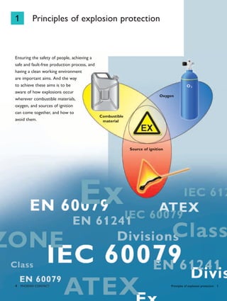
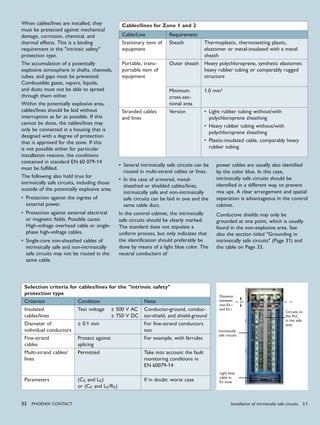
![PHoENIx CoNTACT 41
Housing
IP54*
Housing
IP54*Housing,
e.g., Ex d
Housing,
e.g., Ex d
Sensor/
actuator
Ex ia
Sensor/
actuator
Ex n
Sensor/
actuator
Ex n
Sensor/
actuator
Ex ia
Sensor/
actuator
Ex ia
Sensor/
actuator
Ex ic
Sensor/
actuator
Ex ib
Sensor/
actuator
Zone 0 Zone 1 Zone 2
MINI
Ex n
MINI
Ex n
MINI
Ex n
MACX-Ex
[Ex ia]
Ex n
MACX-Ex
[Ex ia]
Ex n
MACX-Ex
[Ex ia]
Ex n
MACX-Ex
[Ex ia]
Ex n
MACX-Ex
[Ex ia]
Ex n
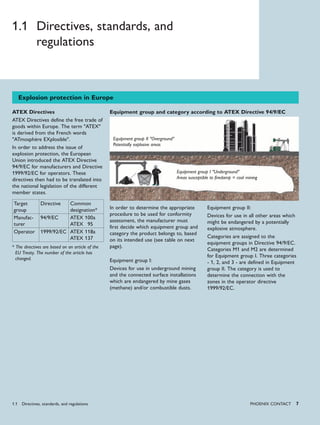
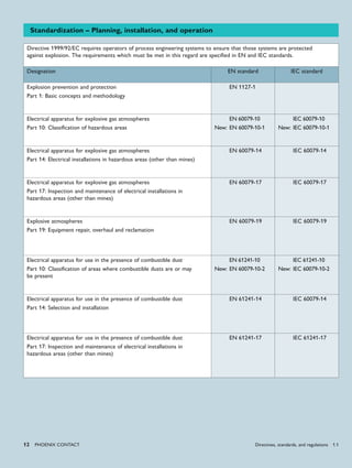
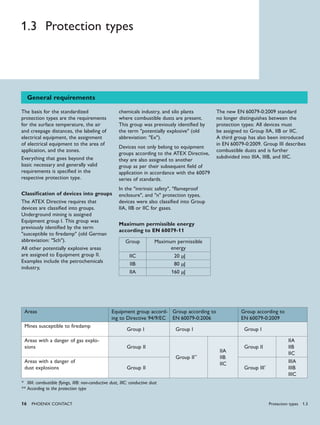
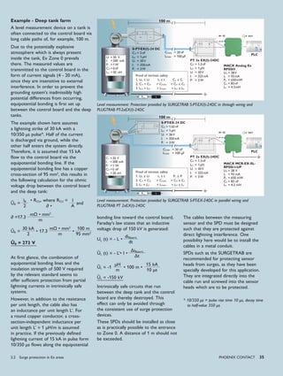
Installation requirements
The figure shows a range of options
for installing electrical devices in
areas with a danger of gas explosions.
Special requirements regarding the
configuration, selection, and installation
of electrical installations in areas with a
danger of gas explosions can be found
in EN 60079-14. EN 61241-14 should
be observed for information on the
installation of electrical equipment
in areas containing combustible dust.
Other important factors when it comes
to running systems in potentially
explosive areas are inspection,
maintenance, and repairs. Specifications
in this regard can be found in
EN 60079-17 and EN 60079-19.
Example of the installation of electrical devices for the purpose of transmitting signals
* Use of a suitable housing approved for use in Zone 2
Safe area
2.5 Installation examples](https://image.slidesharecdn.com/explosionprotection-theoryandpractice-140424155213-phpapp01/85/Explosion-protection-theory-and-practice-41-320.jpg)
![1
1 ia
G IIB T6
( ) [ ]
1 G (1) G
ia ia
IIB IIC
42 PHoENIx CoNTACT
2.6 Proof of intrinsic safety
General considerations
Comparison of the labeling of an intrinsically safe field device in Zone 0 and an item of
associated equipment
Field device Evaluation of the Ex mark Associated
equipment
X II G Ex ia IIB T6 Category of the field device corresponds to the
specified zone
X II G Ex IIB T6 Protection type is permitted in the specified zone
X II 1 Ex ia The device is permitted for use in the prevailing
gas atmosphere
Associated equipment is identified as such by
means of brackets
X II 1 G Ex ia IIC
X II Ex ia IIB T6 Category of the associated equipment at least cor-
responds to the category of the field device
X II [Ex ia] IIC
X II 1 G Ex IIB T6 Protection type of the associated equipment
matches that of the field device
X II (1) G [Ex ] IIC
X II 1 G Ex ia T6 The associated equipment is approved for the
same gas group or one of a higher order
X II (1) G [Ex ia]
The operator determines the zone, the
group, and the temperature class for the
field device, based on the risk analysis
which has been carried out.
The comparisons specified here must be
performed when selecting appropriate
devices for the application in question.
Description of safety-related data
Description Abbreviation
For field device:
Max. input voltage
Max. input power
Max. internal capacitance
Max. internal inductance
Ui
Ii
Ci
Li
For associated equipment:
Max. output voltage
Max. output power
Max. external capacitance
Max. external inductance
Uo
Io
Co
Lo
For cable/line:
Cable/line capacitance
Cable/line inductance
Cc
Lc
Item of associated electrical equipment, e.g.,
MACX MCR-EX-SL-RPSS EI
X II (1) G [Ex ia] IIC
Example of a circuit
Field device
X II 1 G Ex ia IIB T6
PLC
Safe area
Ui ≥ Uo
Ii ≥ Io
Pi ≥ Po
Ci + Cc ≤ Co
Li + Lc ≤ Lo
Dimensioning of intrinsically safe circuits
Proof of intrinsic safety 2.6](https://image.slidesharecdn.com/explosionprotection-theoryandpractice-140424155213-phpapp01/85/Explosion-protection-theory-and-practice-42-320.jpg)
![PHoENIx CoNTACT 43
Function:
The devices transmit analog signals from
sensors in the field to a controller using
an electrically isolated method.
Input isolator:
The sensor in the field is not supplied
with power by the input isolator.
Repeater power supply:
Additionally supplies the sensor with the
required power.
HART repeater power supply:
Additionally modulated digital data signal
is transmitted.
Function:
The devices transmit analog signals from
a controller to an actuator in the field
using an electrically isolated method.
Output isolator:
The output isolator can also be Smart-
capable. In this way, actuators in the
field can be configured using the HART
protocol.
Comparison of the safety-related data from the hazardous area approval
for a repeater power supply
Field
device*
Cable/Line Associated
equipment
Example
MACX MCR-EX-SL-RPSSI-I
Ui ≥ Uo 25.2 V
Ii ≥ Io 93 mA
Pi ≥ Po 587 mW
Ci + Cc (140…200 nF/km approx.) ≤ Co IIC: 107 nF
Li + Lc (0.8…1 mH/km approx.) ≤ Lo IIC: 2 mH
Comparison of the safety-related data from the hazardous area approval
Field
device*
Cable/Line Associated
equipment
Example
MACX MCR-EX-SL-IDSI-I
Ui ≥ Uo 27.7 V
Ii ≥ Io 92 mA
Pi ≥ Po 636 mW
Ci + Cc (140…200 nF/km approx.) ≤ Co IIC = 85 nF
Li + Lc (0.8…1 mH/km approx.) ≤ Lo IIC = 2 mH
Analog IN
Analog OUT
Item of associated electrical equipment, e.g.,
MACX MCR-EX-SL-RPSSI-I
X II (1) G [Ex ia] IIC
Example of a circuit
Field device
X II 1 G Ex ia IIB T6
PLC
Safe area
Item of associated electrical equipment, e.g.,
MACX MCR-EX-SL-IDSI-I
X II (1) G [Ex ia] IIC
Example of a circuit
Field device
X II 1 G Ex ia IIB T6
PLC
Safe area
* The values for the field device can be derived from the relevant EC-type examination certificate.
This comparison is based on the assumption that Ci is < 1% of Co and Li is < 1% of Lo.
* The values for the field device can be derived from the relevant EC-type examination certificate.
This comparison is based on the assumption that Ci is < 1% of Co and Li is < 1% of Lo.
2.6 Proof of intrinsic safety](https://image.slidesharecdn.com/explosionprotection-theoryandpractice-140424155213-phpapp01/85/Explosion-protection-theory-and-practice-43-320.jpg)
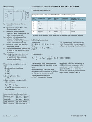
![44 PHoENIx CoNTACT
Digital IN
Digital OUT
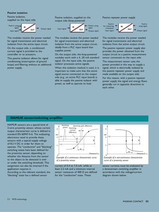
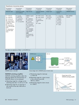
NAMUR isolation amplifier
The devices transmit binary signals from
sensors in the field to the controller
using an electrically isolated method.
This signal is created in the field by a
switch or a NAMUR sensor. On the
output side of the isolation amplifier, the
signal is transferred to the controller as
a binary signal either through a relay or
through a transistor.
An additional resistance circuit enables
open circuit detection to be performed
even for simple switches.
1
3
With open circuit
detection
Without open circuit
detection
1
3
The resistance is used to ensure that a
minimum current is always flowing, even
when the switch is open. In this way, a
cable break can be identified.
Solenoid driver
Solenoid drivers link a switch or voltage
source installed in the safe area to a
field device using an electrically isolated
method.
Intrinsically safe solenoid valves, alarm
modules or other intrinsically safe
devices can be connected, and simple
electrical equipment such as LEDs can
be operated.
Example of a circuit
Example of a circuit
Field device
X II 1 G Ex ia IIB T6
Field device
X II 1 G Ex ia IIB T6
PLC
PLC
Safe area
Safe area
Item of associated electrical equipment, e.g.,
MACX MCR-EX-SL-NAM-R
X II (1) G [Ex ia] IIC
Item of associated electrical equipment, e.g.,
MACX MCR-EX-SL-SD-24-48-LP
X II (1) G [Ex ia] IIC
Comparison of the safety-related data from the hazardous area approval
Field
device*
Cable/Line Associated
equipment
Example
MACX MCR-EX-SL-NAM-R
Ui ≥ Uo 9.6 V
Ii ≥ Io 10 mA
Pi ≥ Po 25 mW
Ci + Cc (140…200 nF/km approx.) ≤ Co IIC = 510 nF
Li + Lc (0.8…1 mH/km approx.) ≤ Lo IIC = 100 mH
* The values for the field device can be derived from the relevant EC-type examination certificate or
will have to be determined specifically for simple electrical equipment.
This comparison is based on the assumption that Ci is < 1% of Co and Li is < 1% of Lo.
In the case of simple electrical
equipment, e.g., simple switches, only
the inductance and capacitance values
of the cables/lines are used for the
comparison of safety-related data.
For additional requirements relating
to "simple electrical equipment", see
Page 21.
Proof of intrinsic safety 2.6](https://image.slidesharecdn.com/explosionprotection-theoryandpractice-140424155213-phpapp01/85/Explosion-protection-theory-and-practice-44-320.jpg)
![ϑ
46 PHoENIx CoNTACT
ϑ
Temperature measurement
Temperature transducer
Temperature transducers convert
measurement signals from variable
resistors (e.g., Pt100) or thermocouples
(e.g., J, K) into standard signals
0…20 mA, 4…20 mA.
2-, 3-, or 4-wire measurement
technology can be used for Pt100
resistors.
Temperature measurement
The temperature inside a heating
oil tank is to be monitored. The
measurement is performed using a Pt100
resistor. This can be viewed as an item
of simple electrical equipment according
to EN 60079-11, since it is passive.
Simple electrical equipment must meet
the requirements of EN 60079-11 and
must not impair the intrinsic safety of
the circuit in which it is used.
If certified, intrinsically safe sensors are
used, this reduces the amount of testing
work required.
There are two possibilities for
converting the measurement signal into
a standard signal for the controller.
PLC
Simple electrical
equipment
Safe areaExample of a circuit
Item of associated electrical equipment, e.g.,
MACX MCR-EX-SL-RTD-I
X II (1) G [Ex ia] IIC
Case I
The measurement signal of the Pt100
resistor is routed via a signal cable to
the temperature transducer MACX
MCR-EX-SL-RTD-I. In the measuring
transducer, the temperature signal is
converted into a standard signal, and
the intrinsically safe and non-intrinsically
safe circuits are isolated at the same
time. The measuring transducer is an
item of associated equipment of the
"intrinsic safety Ex ia" protection type.
It is installed in a control cabinet in
the safe area. In this case, the circuit
does not require any further electrical
dimensioning work.
However, it is necessary to make
sure that the sum of all cable/line
capacitances and inductances in the
intrinsically safe circuit does not exceed
the data specified by the measuring
transducer.
Comparison of the safety-related data from the hazardous area approval
Pt100
resistor*
Cable/Line Associated
equipment
Example
MACX MCR-EX-SL-RTD-I
– Uo 6 V
– Io 6.3 mA
– Po 9.4 mW
+ Cc (140…200 nF/km approx.) < Co IIB = 6.9 μF
IIC= 1.4 μF
+ Lc (0.8…1 mH/km approx.) < Lo IIB = 100 mH
IIC = 100 mH
Example for case I
* Passive acc. to EN 60079-11
Proof of intrinsic safety 2.6](https://image.slidesharecdn.com/explosionprotection-theoryandpractice-140424155213-phpapp01/85/Explosion-protection-theory-and-practice-46-320.jpg)
![ϑ
PHoENIx CoNTACT 47
ϑ
Case II
In the second case, the conversion of
the temperature signal to a standard
signal takes place near the measuring
point, in other words in the potentially
explosive area. The temperature head
transmitter MCR-FL-HT-TS-I-Ex is
used for this. The standard signal is
then routed to repeater power supply
MACX MCR-EX-SL-RPSSI-I, which is
installed in the safe area. The isolation of
the intrinsically safe and non-intrinsically
safe circuits takes place in the repeater
power supply. As in the first case,
no special conditions have to be met
for the Pt100 resistor and the head
transducer. The safety-relevant data of
the electrical equipment, the intrinsically
safe temperature head transmitter, and
the repeater power supply as associated
equipment must be compared.
The voltage, current, and energy of
the repeater power supply must be
lower than the permitted input values
of the intrinsically safe temperature
head transmitter. In addition, it is
necessary to make sure that the sum of
all capacitances and inductances in the
intrinsically safe circuit does not exceed
the data specified by the repeater power
supply. This also includes the technical
data of the cables and lines of the
intrinsically safe circuit.
PLC
Example of a circuit Safe area
Intrinsically safe temperature head
transmitter, e.g.,
MCR-FL-HT-TS-I-Ex
X II 2 G Ex ia IIB T6
Item of associated electrical equipment, e.g.,
MACX MCR-EX-SL-RPSSI-I
X II (1) G [Ex ia] IIC
Simple electrical
equipment
Comparison of the safety-related data from the hazardous area approval
Pt100
resistor*
Cable/
Line
Associated
equipment
Example
MCR-FL-HT-TS-I-Ex
Cable/
Line
Associated
equipment
Example
MACX MCR-EX-SL-RPSSI-I
– Uo Ui = 30 V > Uo 25.2 V
– Io Ii = 100 mA > Io 93 mA
– Po Pi = 750 mW < Po 587 mW
+ Cc < Co Ci ≈ 0 + Cc < Co IIC= 107 μF
+ Lc < Lo Li ≈ 0 + Lc < Lo IIC = 2 mH
Example for case II
* Passive acc. to EN 60079-11
2.6 Proof of intrinsic safety](https://image.slidesharecdn.com/explosionprotection-theoryandpractice-140424155213-phpapp01/85/Explosion-protection-theory-and-practice-47-320.jpg)

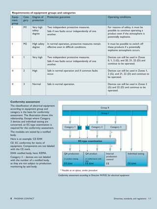
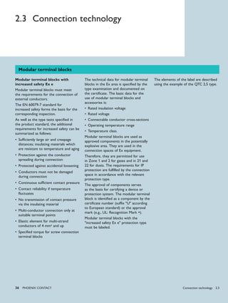
![2200 Hz
2200 Hz1200 Hz
1200 Hz
2200 Hz
"0"
"0""1"
"1"
"0"
20 mA
4 mA
t
I
4-20 mA
iii
1.2-2.2 kHz1.2-2.2 kHz
ϑ
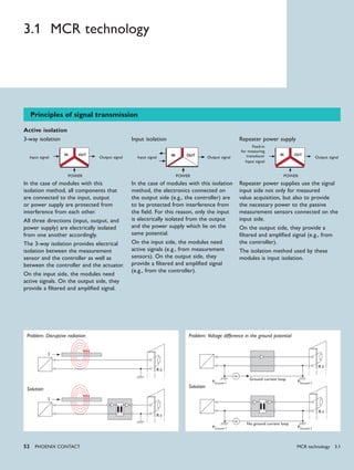
PHoENIx CoNTACT 55
Smart-capable devices - HART protocol
In the process industry, a configuration
must be performed or diagnostic data
determined for a large number of analog
field devices during commissioning and
servicing, as well as during operation.
To enable such communication with
field devices, digital information is
superimposed on the analog signal. For
this purpose, all the devices involved
must be Smart-capable.
In practice, the HART protocol has
become established for this type of
communication.
Since this technology is currently the
most widely used, the "Smart" topic will
be explained on this basis.
With the HART protocol, the
transmission of the digital information
is modulated to the analog 4 - 20 mA
signal with the help of frequency shift
keying (FSK).
In general, two possible operating modes
are distinguished:
"Point-to-point" mode, in which
communication is only possible with
one field device connected in the
4 - 20 mA circuit, and "multi-drop"
mode, in which up to 15 field devices in
the circuit can be connected in parallel.
These two operating modes basically
differ in the fact that in "point-to-point"
mode, the analog 4 - 20 mA signal can
continue to be used in the usual way
and transmits the desired process signal.
In this case, additional data can also be
transmitted in digital form. In "multi-
drop" mode, a current signal of 4 mA
is used in the field device as a carrier
medium to transfer the exclusively digital
information to and from the connected
field devices.
The devices can be connected in point-
to-point mode as well as in multi-drop
mode (with up to 15 parallel devices).
In the case of point-to-point mode,
the 4 - 20 mA signal remains available
as a process signal as usual. Multi-drop
mode requires an injected minimum
current of 4 mA as a carrier for HART
communication.
The aids that are used to implement this
functionality depend on the technical
infrastructure of the system installation.
The diagnostics and configuration of
the field devices can be carried out
directly in the field at the terminals of
the interface devices, with the help of
a hand-held device. If the HART data is
transmitted to higher-level engineering
tools with HART multiplexers or via
I/O modules of the control level,
then they can also be used by asset
management systems, for example.
Asset management systems offer the
possibility of performing configuration
and diagnostic functions automatically
and additionally provide the technical
framework for archiving the field device
data (e.g., adjustable parameters).
Design with HART signal supply
Depending on the physical structure,
the control level can also use HART
communication to influence the field
device (e.g., setpoint, measuring range
change) from the controller or to
request additional data (e.g., process
signals).
As in standard installations (without
HART communication), interface devices
are used to connect the field devices
(sensors and actuators) and the I/O level
of the controller. To transmit the data
that has been modulated to the analog
4 - 20 mA signal reliably and without
interference, the interface devices used
must be Smart-capable. This means that
the HART signal must not be influenced
at all during operation, e.g., by filters.
In the case of interface devices for
signal conditioning with electrical
isolation, the HART signal is decoupled
in the interface device and transmitted
separately.
The connected load in the circuit must
also be taken into account, as the HART
signal requires a terminating resistance
of 250 Ω.
Safe area
Repeater power supply
[Ex ia]
HART configuration
device
Smart transmitter
Ex ia
Analog signal superimposed with
digital HART signal
3.1 MCR technology](https://image.slidesharecdn.com/explosionprotection-theoryandpractice-140424155213-phpapp01/85/Explosion-protection-theory-and-practice-55-320.jpg)


This document provides an overview of explosion protection principles and guidelines. It discusses the risks of explosions from combustible gases, vapors, and dusts. It also summarizes the key standards and directives around explosion protection from Europe (ATEX), North America (NEC/CEC), and international standards. The document outlines explosion protection concepts like classification of hazardous areas, protection types, and conformity assessment procedures.


