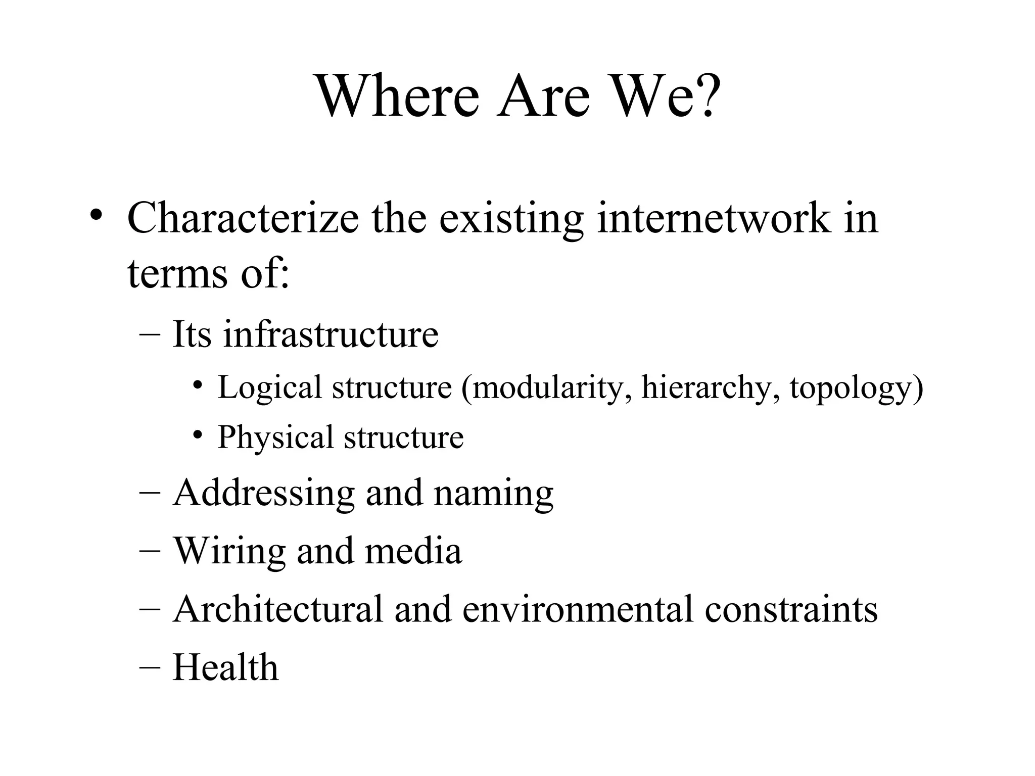
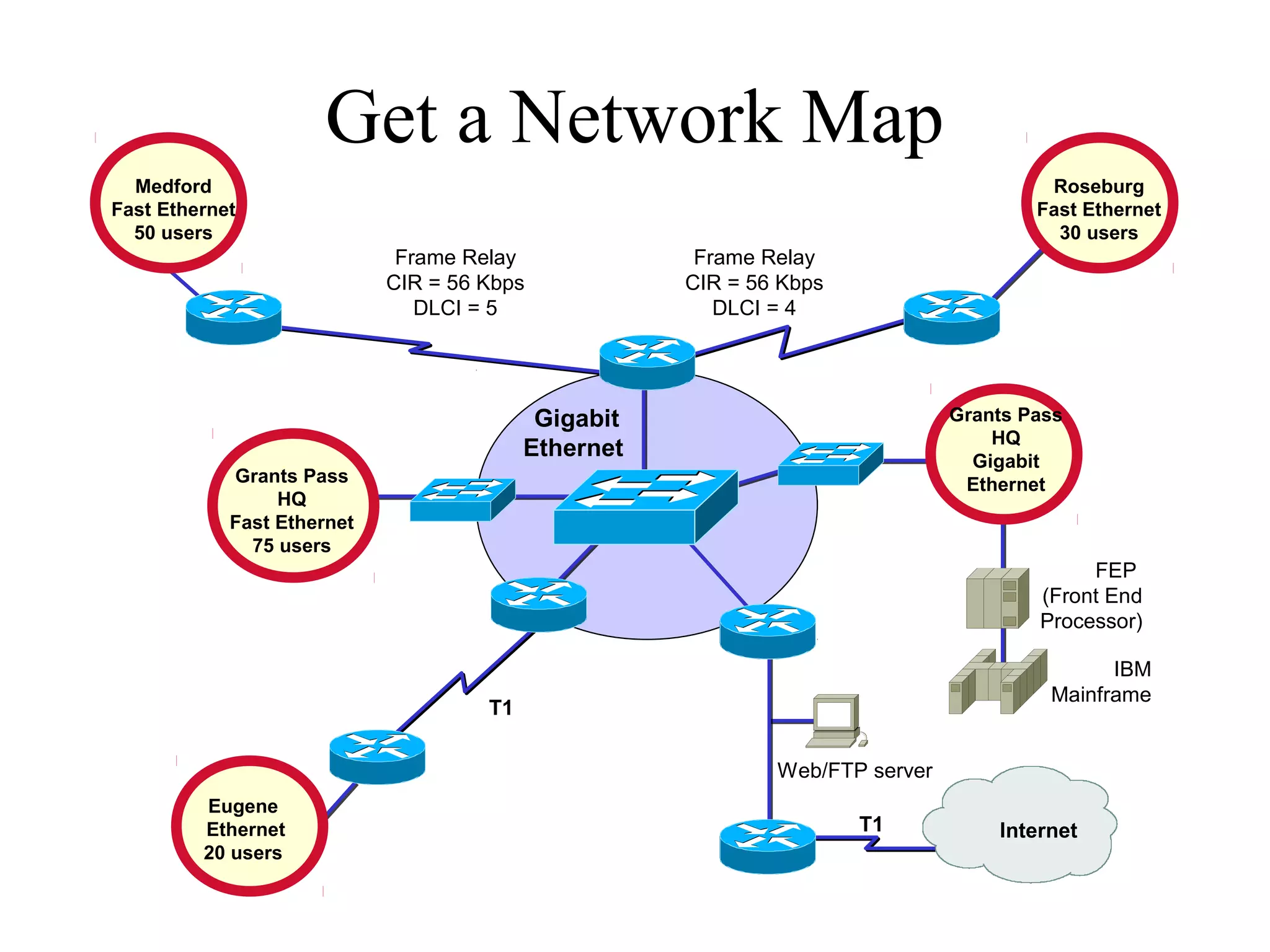
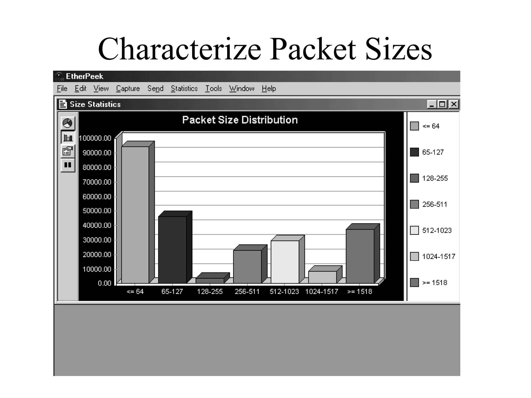
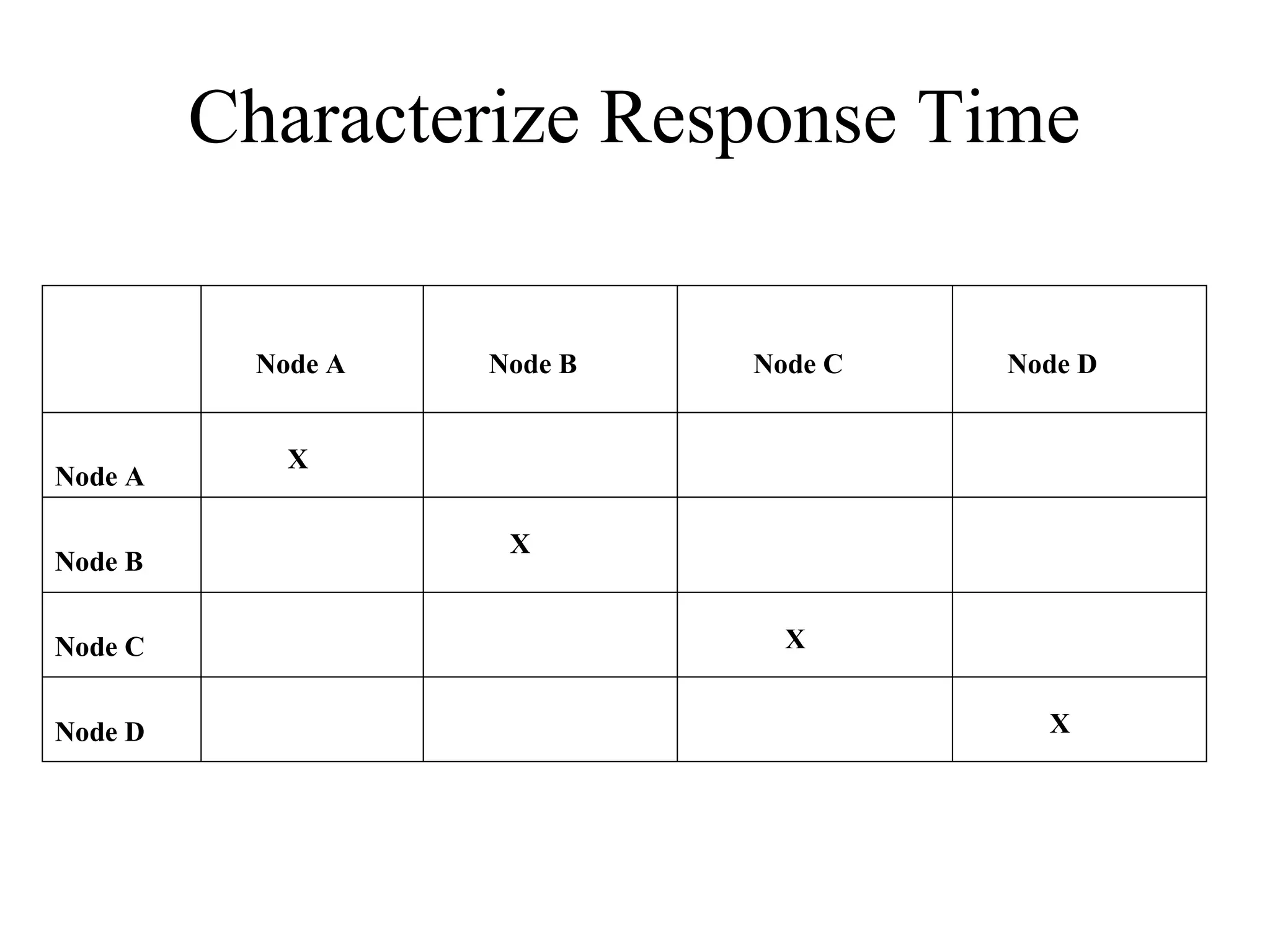
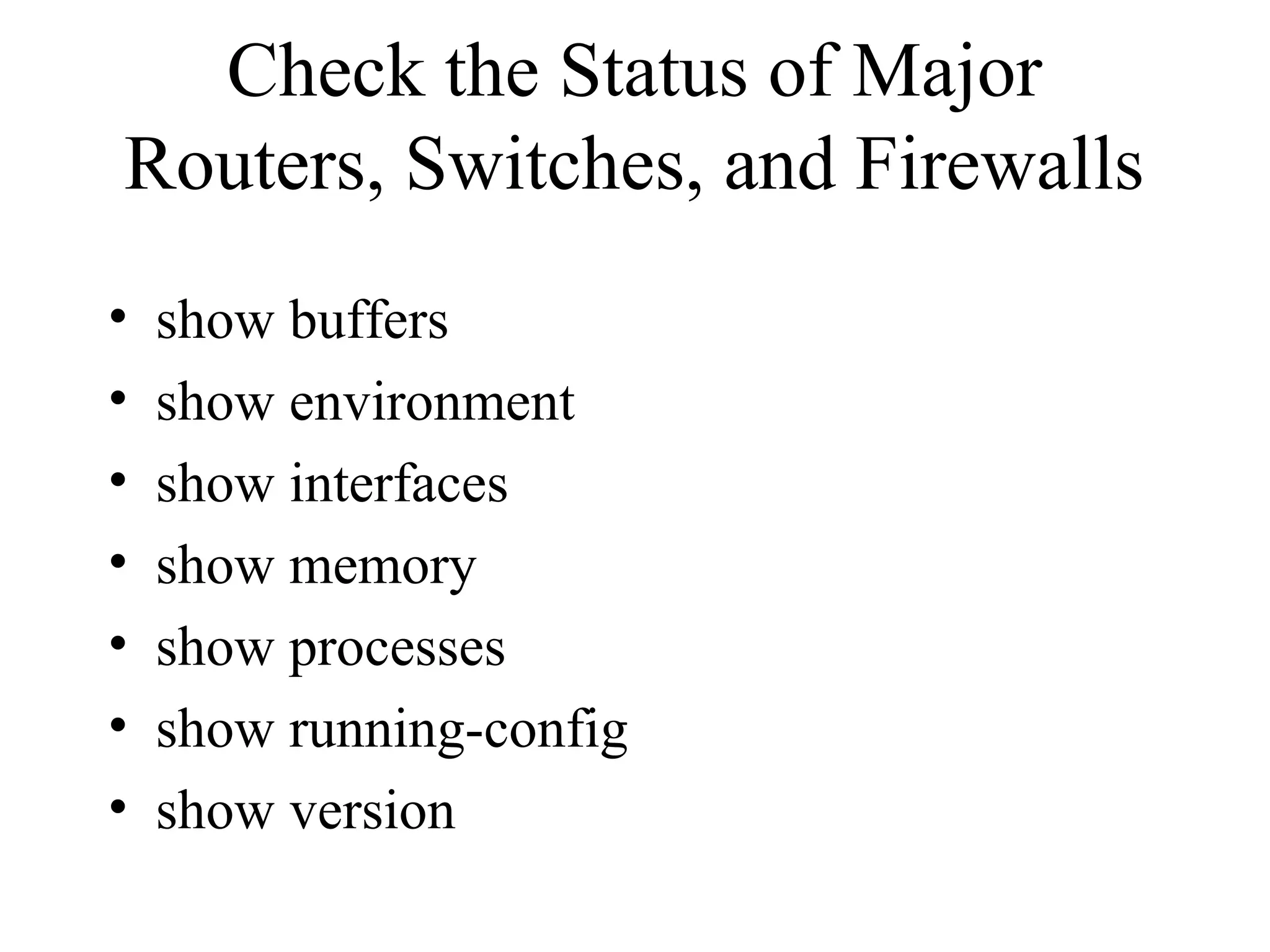
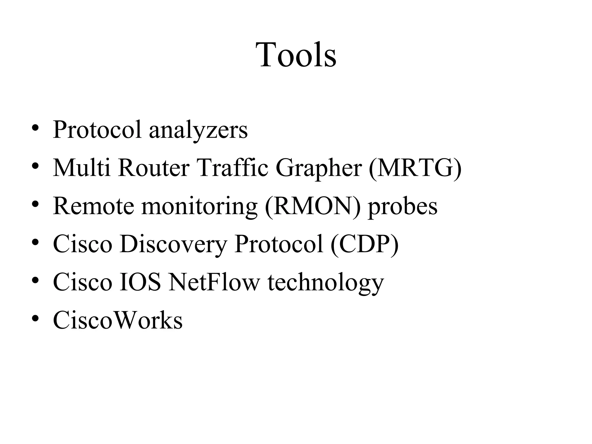
Top-Down Network Design

            Chapter Three

   Characterizing the Existing Internetwork


       Copyright 2010 Cisco Press & Priscilla Oppenheimer
What’s the Starting Point?
• According to Abraham Lincoln:
  – “If we could first know where we are and
    whither we are tending, we could better judge
    what to do and how to do it.”
Where Are We?
• Characterize the existing internetwork in
  terms of:
  – Its infrastructure
       • Logical structure (modularity, hierarchy, topology)
       • Physical structure
  –   Addressing and naming
  –   Wiring and media
  –   Architectural and environmental constraints
  –   Health
Get a Network Map
  Medford                                                                              Roseburg
Fast Ethernet                                                                         Fast Ethernet
  50 users                                                                              30 users
                             Frame Relay              Frame Relay
                            CIR = 56 Kbps            CIR = 56 Kbps
                               DLCI = 5                 DLCI = 4


                                           Gigabit                            Grants Pass
                                                                                  HQ
                                          Ethernet                              Gigabit
            Grants Pass                                                        Ethernet
                 HQ
            Fast Ethernet
              75 users
                                                                                           FEP
                                                                                      (Front End
                                                                                      Processor)

                                                                                             IBM
                                                                                       Mainframe
                                     T1

                                                             Web/FTP server
         Eugene
         Ethernet                                                    T1           Internet
         20 users
Characterize Addressing and
             Naming
• IP addressing for major devices, client
  networks, server networks, and so on
• Any addressing oddities, such as
  discontiguous subnets?
• Any strategies for addressing and naming?
  – For example, sites may be named using airport
    codes
     • San Francisco = SFO, Oakland = OAK
Discontiguous Subnets

                              Area 0
                             Network
                           192.168.49.0

Router A                                                Router B


          Area 1                                 Area 2
   Subnets 10.108.16.0 -                  Subnets 10.108.32.0 -
       10.108.31.0                            10.108.47.0
Characterize the Wiring and
                Media
•   Single-mode fiber
•   Multi-mode fiber
•   Shielded twisted pair (STP) copper
•   Unshielded-twisted-pair (UTP) copper
•   Coaxial cable
•   Microwave
•   Laser
•   Radio
•   Infra-red
Campus Network Wiring
                         Horizontal        Work-Area
                          Wiring            Wiring

                                      Wallplate
            Telecommunications
               Wiring Closet


 Vertical
 Wiring
(Building
Backbone)


                                   Main Cross-Connect Room                   Intermediate Cross-Connect Room
                                  (or Main Distribution Frame)              (or Intermediate Distribution Frame)


                                                                  Campus
                 Building A - Headquarters                       Backbone                  Building B
Architectural Constraints
• Make sure the following are sufficient
  –   Air conditioning
  –   Heating
  –   Ventilation
  –   Power
  –   Protection from electromagnetic interference
  –   Doors that can lock
Architectural Constraints

• Make sure there’s space for:
  –   Cabling conduits
  –   Patch panels
  –   Equipment racks
  –   Work areas for technicians installing and
      troubleshooting equipment
Issues for Wireless Installations

•   Reflection
•   Absorption
•   Refraction
•   Diffraction
Check the Health of the Existing
         Internetwork
•   Performance
•   Availability
•   Bandwidth utilization
•   Accuracy
•   Efficiency
•   Response time
•   Status of major routers, switches, and
    firewalls
Characterize Availability

                           Date and Duration   Cause of Last   Fix for Last
             MTBF   MTTR   of Last Major       Major           Major
                           Downtime            Downtime        Downtime


Enterprise


Segment 1


Segment 2


Segment n
Network Utilization in Minute
             Intervals
                         Network Utilization

  16:40:00

  16:43:00

  16:46:00

  16:49:00

  16:52:00

  16:55:00                                                     Series1
Time
  16:58:00

  17:01:00

  17:04:00

  17:07:00

  17:10:00
             0   1   2       3                 4   5   6   7
                                 Utilization
Network Utilization in Hour
               Intervals
                                 Network Utilization


  13:00:00


  14:00:00


  15:00:00                                                                     Series1
Time


  16:00:00


  17:00:00


             0   0.5   1   1.5        2              2.5   3   3.5   4   4.5
                                       Utilization
Bandwidth Utilization by
                    Protocol
             Relative      Absolute                  Multicast
                                         Broadcast
             Network       Network                   Rate
                                         Rate
             Utilization   Utilization


Protocol 1


Protocol 2


Protocol 3


Protocol n
Characterize Packet Sizes
Characterize Response Time

          Node A   Node B   Node C   Node D


            X
Node A

                    X
Node B


Node C                        X


Node D                                 X
Check the Status of Major
Routers, Switches, and Firewalls
•   show buffers
•   show environment
•   show interfaces
•   show memory
•   show processes
•   show running-config
•   show version
Tools
•   Protocol analyzers
•   Multi Router Traffic Grapher (MRTG)
•   Remote monitoring (RMON) probes
•   Cisco Discovery Protocol (CDP)
•   Cisco IOS NetFlow technology
•   CiscoWorks
Summary
• Characterize the existing internetwork before
  designing enhancements
• Helps you verify that a customer’s design
  goals are realistic
• Helps you locate where new equipment will
  go
• Helps you cover yourself if the new network
  has problems due to unresolved problems in
  the old network
Review Questions
• What factors will help you decide if the existing
  internetwork is in good enough shape to support new
  enhancements?
• When considering protocol behavior, what is the
  difference between relative network utilization and
  absolute network utilization?
• Why should you characterize the logical structure of
  an internetwork and not just the physical structure?
• What architectural and environmental factors should
  you consider for a new wireless installation?

Chapter03

  • 1.
    Top-Down Network Design Chapter Three Characterizing the Existing Internetwork Copyright 2010 Cisco Press & Priscilla Oppenheimer
  • 2.
    What’s the StartingPoint? • According to Abraham Lincoln: – “If we could first know where we are and whither we are tending, we could better judge what to do and how to do it.”
  • 3.
    Where Are We? •Characterize the existing internetwork in terms of: – Its infrastructure • Logical structure (modularity, hierarchy, topology) • Physical structure – Addressing and naming – Wiring and media – Architectural and environmental constraints – Health
  • 4.
    Get a NetworkMap Medford Roseburg Fast Ethernet Fast Ethernet 50 users 30 users Frame Relay Frame Relay CIR = 56 Kbps CIR = 56 Kbps DLCI = 5 DLCI = 4 Gigabit Grants Pass HQ Ethernet Gigabit Grants Pass Ethernet HQ Fast Ethernet 75 users FEP (Front End Processor) IBM Mainframe T1 Web/FTP server Eugene Ethernet T1 Internet 20 users
  • 5.
    Characterize Addressing and Naming • IP addressing for major devices, client networks, server networks, and so on • Any addressing oddities, such as discontiguous subnets? • Any strategies for addressing and naming? – For example, sites may be named using airport codes • San Francisco = SFO, Oakland = OAK
  • 6.
    Discontiguous Subnets Area 0 Network 192.168.49.0 Router A Router B Area 1 Area 2 Subnets 10.108.16.0 - Subnets 10.108.32.0 - 10.108.31.0 10.108.47.0
  • 7.
    Characterize the Wiringand Media • Single-mode fiber • Multi-mode fiber • Shielded twisted pair (STP) copper • Unshielded-twisted-pair (UTP) copper • Coaxial cable • Microwave • Laser • Radio • Infra-red
  • 8.
    Campus Network Wiring Horizontal Work-Area Wiring Wiring Wallplate Telecommunications Wiring Closet Vertical Wiring (Building Backbone) Main Cross-Connect Room Intermediate Cross-Connect Room (or Main Distribution Frame) (or Intermediate Distribution Frame) Campus Building A - Headquarters Backbone Building B
  • 9.
    Architectural Constraints • Makesure the following are sufficient – Air conditioning – Heating – Ventilation – Power – Protection from electromagnetic interference – Doors that can lock
  • 10.
    Architectural Constraints • Makesure there’s space for: – Cabling conduits – Patch panels – Equipment racks – Work areas for technicians installing and troubleshooting equipment
  • 11.
    Issues for WirelessInstallations • Reflection • Absorption • Refraction • Diffraction
  • 12.
    Check the Healthof the Existing Internetwork • Performance • Availability • Bandwidth utilization • Accuracy • Efficiency • Response time • Status of major routers, switches, and firewalls
  • 13.
    Characterize Availability Date and Duration Cause of Last Fix for Last MTBF MTTR of Last Major Major Major Downtime Downtime Downtime Enterprise Segment 1 Segment 2 Segment n
  • 14.
    Network Utilization inMinute Intervals Network Utilization 16:40:00 16:43:00 16:46:00 16:49:00 16:52:00 16:55:00 Series1 Time 16:58:00 17:01:00 17:04:00 17:07:00 17:10:00 0 1 2 3 4 5 6 7 Utilization
  • 15.
    Network Utilization inHour Intervals Network Utilization 13:00:00 14:00:00 15:00:00 Series1 Time 16:00:00 17:00:00 0 0.5 1 1.5 2 2.5 3 3.5 4 4.5 Utilization
  • 16.
    Bandwidth Utilization by Protocol Relative Absolute Multicast Broadcast Network Network Rate Rate Utilization Utilization Protocol 1 Protocol 2 Protocol 3 Protocol n
  • 17.
  • 18.
    Characterize Response Time Node A Node B Node C Node D X Node A X Node B Node C X Node D X
  • 19.
    Check the Statusof Major Routers, Switches, and Firewalls • show buffers • show environment • show interfaces • show memory • show processes • show running-config • show version
  • 20.
    Tools • Protocol analyzers • Multi Router Traffic Grapher (MRTG) • Remote monitoring (RMON) probes • Cisco Discovery Protocol (CDP) • Cisco IOS NetFlow technology • CiscoWorks
  • 21.
    Summary • Characterize theexisting internetwork before designing enhancements • Helps you verify that a customer’s design goals are realistic • Helps you locate where new equipment will go • Helps you cover yourself if the new network has problems due to unresolved problems in the old network
  • 22.
    Review Questions • Whatfactors will help you decide if the existing internetwork is in good enough shape to support new enhancements? • When considering protocol behavior, what is the difference between relative network utilization and absolute network utilization? • Why should you characterize the logical structure of an internetwork and not just the physical structure? • What architectural and environmental factors should you consider for a new wireless installation?

Editor's Notes

  • #12 Reflection. Reflection causes the signal to bounce back on itself. The signal can interfere with itself in the air and affect the receiver’s ability to discriminate between the signal and noise in the environment. Reflection is caused by metal surfaces such as steel girders, scaffolding, shelving units, steel pillars, and metal doors. Implementing a Wireless LAN (WLAN) across a parking lot can be tricky because of metal cars that come and go. Absorption. Some of the electromagnetic energy of the signal can be absorbed by the material in objects through which it passes, resulting in a reduced signal level. Water has significant absorption properties, and objects such as trees or thick wooden structures can have a high water content. Implementing a WLAN in a coffee shop can be tricky if there are large canisters of liquid coffee. Coffee-shop WLAN users have also noticed that people coming and going can affect the signal level. (On StarTrek, a non-human character once called a human “an ugly giant bag of mostly water”!) Refraction. When an RF signal passes from a medium with one density into a medium with another density, the signal can be bent, much like light passing through a prism. The signal changes direction and may interfere with the non-refracted signal. It can take a different path and encounter other, unexpected obstructions, and arrive at recipients damaged or later than expected. As an example, a water tank not only introduces absorption, but the difference in density between the atmosphere and the water can bend the RF signal. Diffraction. Diffraction, which is similar to refraction, results when a region through which the RF signal can pass easily is adjacent to a region in which reflective obstructions exist. Like refraction, the RF signal is bent around the edge of the diffractive region and can then interfere with that part of the RF signal that is not bent.
  • #17 Relative usage specifies how much bandwidth is used by the protocol in comparison to the total bandwidth currently in use on the segment. Absolute usage specifies how much bandwidth is used by the protocol in comparison to the total capacity of the segment (for example, in comparison to 100 Mbps on Fast Ethernet).