Downloaded 34 times

![Arithmetic Instructions
MUL AB B:A = A * B 1
DIV AB A = [A/B] 1
DA A Decimal adjustment of 1
accumulator according to BCD
code](https://image.slidesharecdn.com/microcontrollerinstructionset-151003175433-lva1-app6891/85/Microcontroller-instruction-set-44-320.jpg)
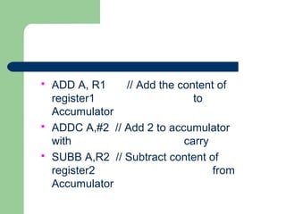
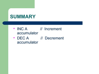
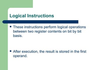
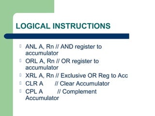
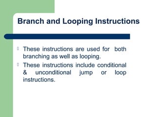
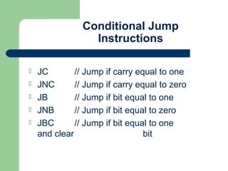
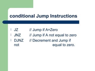


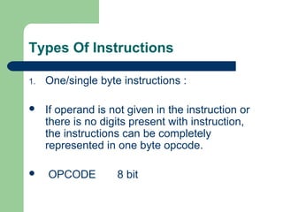
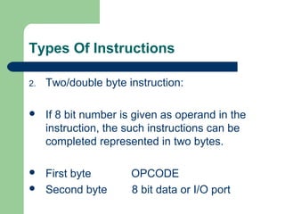
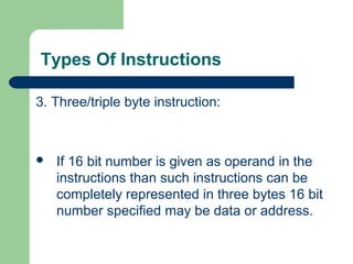
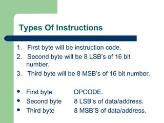
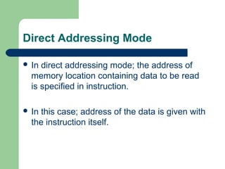
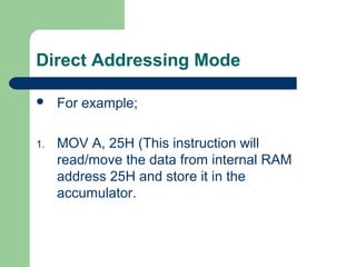
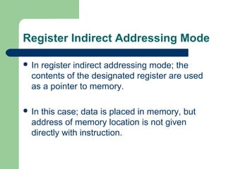
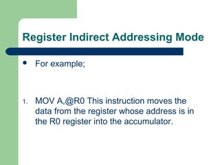
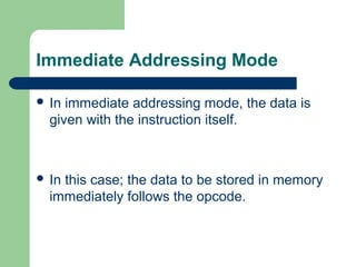
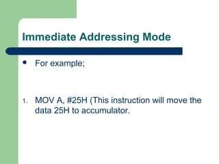
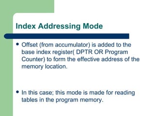
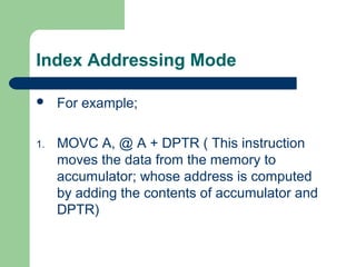
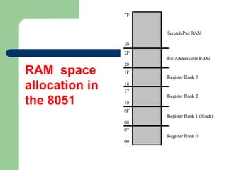
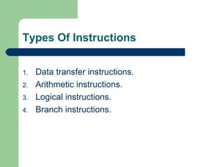
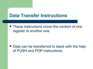
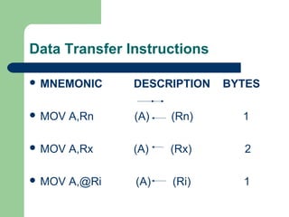
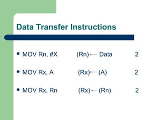
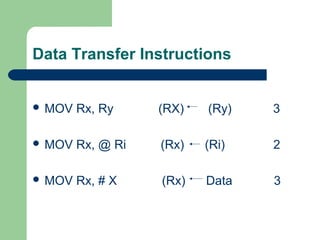
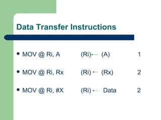
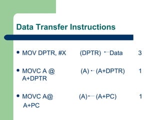
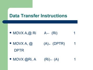
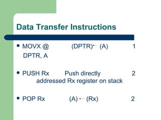
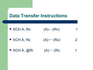
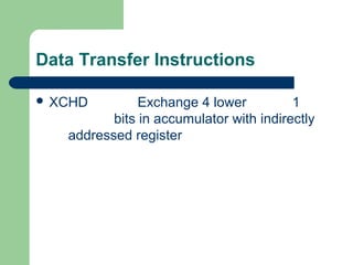
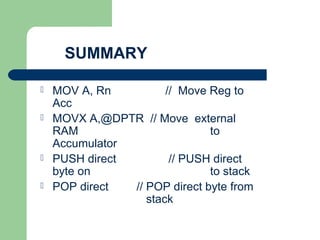
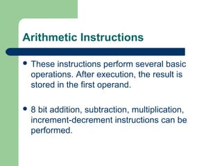
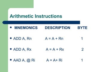
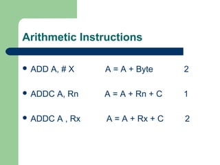
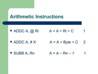
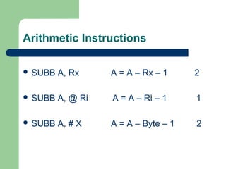
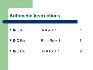
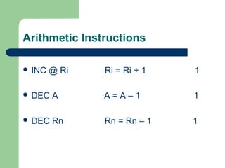
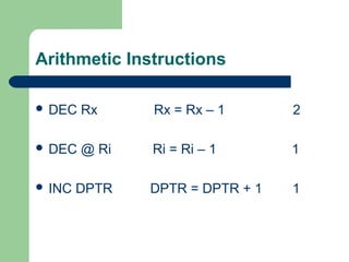
The document discusses various aspects of the 8051 microcontroller such as instruction types, addressing modes, RAM space allocation, and instruction sets. It explains that 8051 instructions are divided into one-byte, two-byte, and three-byte instructions depending on the number of bytes required to represent them. It describes the five addressing modes - register, direct, indirect, immediate, and index. It also provides examples of different instruction types like data transfer, arithmetic, logical, and branching instructions.