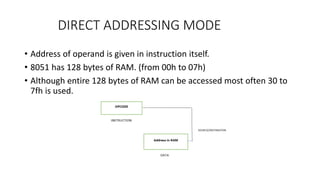
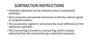
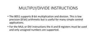
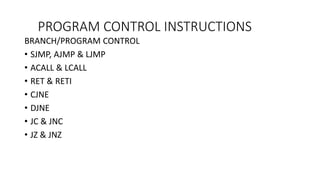
This document discusses instruction syntax and addressing modes in microcontrollers. It provides details on instruction components like labels, opcodes, and operands. It also explains the different addressing modes like immediate, register, direct, indirect, and indexed addressing. The document then covers various instruction types for 8051 microcontrollers like data transfer instructions, arithmetic instructions, and programming control instructions. Specific instructions like MOV, ADD, SUB, and examples are described in detail.
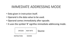
![INDIRECT ADDRESSING MODE
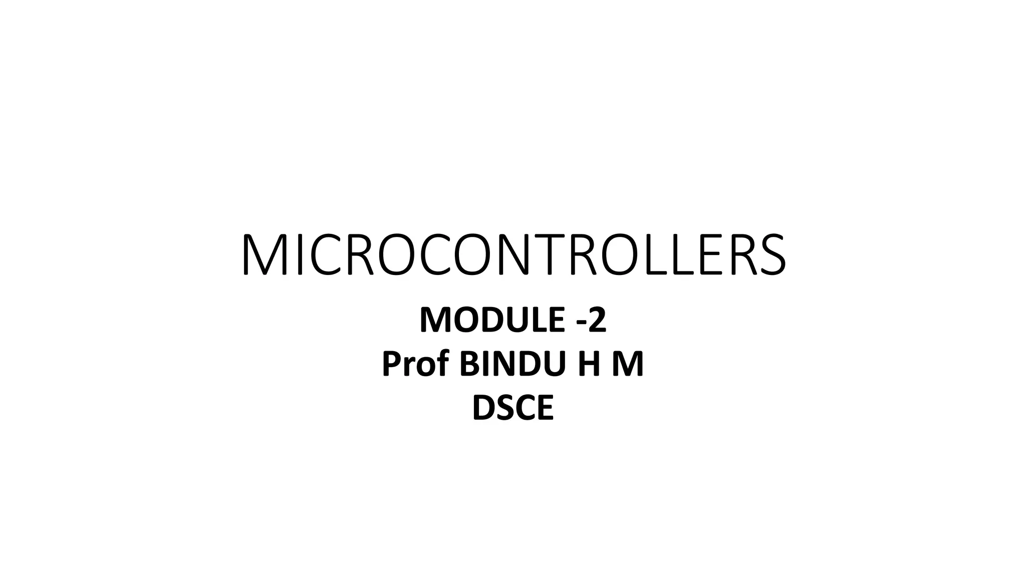
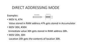
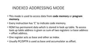
Examples:
• MOV A, @R0
R0 has 54h which is used as address of internal RAM , that contains operand
data.
• MOV @R0, A
[R0] A; Internal RAM location pointed by R0 gets value of A.
• MOVX A, @DPTR ; ‘X’ represents accessing external memory.
‘A’ gets contents of external RAM location whose address is given by DPTR.
If DPTR = 2000h, then A gets content stored in external RAM location 2000h](https://image.slidesharecdn.com/microcontrollers-module27-221127132022-f9fd0988/85/MICROCONTROLLERS-module2-7-pptx-16-320.jpg)
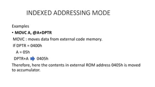
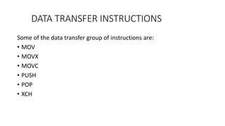
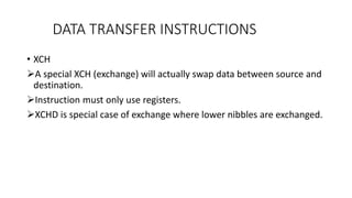

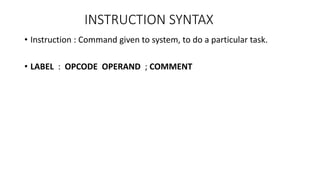
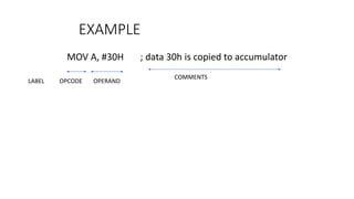
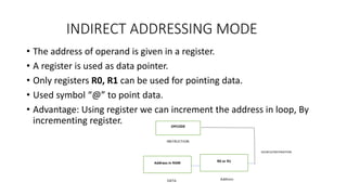
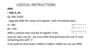
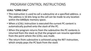
![• ADD A, addr
ADD A, 25H; A—A+[25H]
Add A register with contents of RAM address of 25h and store in A register.
• ADD A, @Rn
ADD A, @R0; A– A+[R0]
Adds A register with contents of location pointed by register. Result is stored
in A.
If R0= 20h,
The 20h is Ram location from where contents should be added.
If 20h has value 35h then A—A+35H.
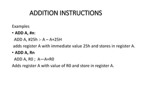
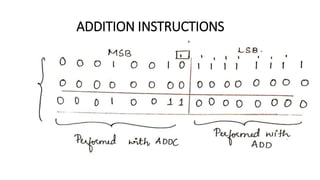
ADDITION INSTRUCTIONS
41H
35H
ABH
40H
21H
20H
19H
18H](https://image.slidesharecdn.com/microcontrollers-module27-221127132022-f9fd0988/85/MICROCONTROLLERS-module2-7-pptx-36-320.jpg)
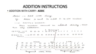
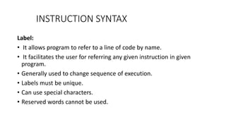
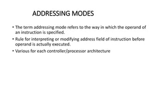
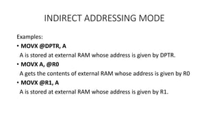
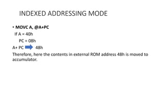
![• ADDC A, addr
ADDC A, 25H ; A– A+[25H] + C.F
Add A register with contents of RAM location of 25h along with carry
flag.
• ADDC A, @Rp
ADDC A, @R0 ; A– A +[R0] + C.F
Add A register with contents of location pointed by R0, with carry flag
of previous addition and store in register A.
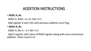
ADDITION INSTRUCTIONS](https://image.slidesharecdn.com/microcontrollers-module27-221127132022-f9fd0988/85/MICROCONTROLLERS-module2-7-pptx-40-320.jpg)
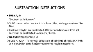
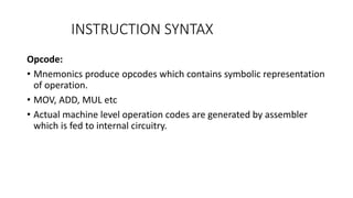
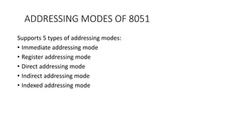
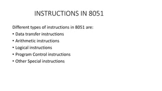
![• SUBB A, addr
SUBB A, 25h
A– A-[25h]-carry flag(if borrow exists)
Contents of Register A are subtracted with contents of RAM location
25h with CF and result is stored in Register A.
SUBTRACTION INSTRUCTIONS](https://image.slidesharecdn.com/microcontrollers-module27-221127132022-f9fd0988/85/MICROCONTROLLERS-module2-7-pptx-44-320.jpg)
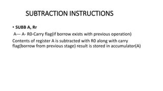
![• SUBB A, @Rn
SUBB A, @Ro
A—A-[Ro]-CF(borrow if exists)
Contents of register A are subtracted with RAM location pointed by
register Ro along with carry flag and result is stored in accumulator A.
SUBTRACTION INSTRUCTIONS](https://image.slidesharecdn.com/microcontrollers-module27-221127132022-f9fd0988/85/MICROCONTROLLERS-module2-7-pptx-45-320.jpg)
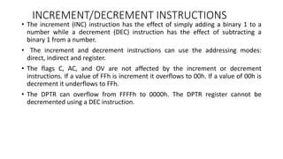
![INCREMENT INSTRUCTIONS
• INC A
A—A+1
Increments the value of register A and stores in register A.
• INC Rr
INC R0
Increments the value of R0 and stores in R0
• INC addr
INC 25h ; [25h]—[25h]+1
Increments the contents of memory address and stores the result in
same location.](https://image.slidesharecdn.com/microcontrollers-module27-221127132022-f9fd0988/85/MICROCONTROLLERS-module2-7-pptx-47-320.jpg)
![• INC @Rp
INC @R0
[@R0] – [@R0]+1
Increments the contents of memory location pointed by R0, Stores the
result in same location.
• INC DPTR
DPTR—DPTR+1
Increments the 16-bit value of DPTR and stores in DPTR.(Requires 2
clock cycles).
INCREMENT INSTRUCTIONS](https://image.slidesharecdn.com/microcontrollers-module27-221127132022-f9fd0988/85/MICROCONTROLLERS-module2-7-pptx-48-320.jpg)
![DECREMENT INSTRUCTIONS
• DEC A
DEC A; A—A-1
Decrements the value A register and stores in A register.
• DEC Rr
DEC R0; R0—R0-1
Decrements the register of RAM register R0 and stores in R0.
• DEC addr
DEC 25h; [25H]—[25H]-1
Decrements the contents of memory address and stores back in same
location .](https://image.slidesharecdn.com/microcontrollers-module27-221127132022-f9fd0988/85/MICROCONTROLLERS-module2-7-pptx-49-320.jpg)
![• DEC @Rp
DEC @R0
[@R0]—[@R0]-1
Decrements the contents of memory location pointed by R0, store in
same location.
DECREMENT INSTRUCTIONS](https://image.slidesharecdn.com/microcontrollers-module27-221127132022-f9fd0988/85/MICROCONTROLLERS-module2-7-pptx-50-320.jpg)
![• ANL addr, A
ANL 25H, A
[25H]– [25H] AND A
Logically AND contents of address with content of A. Store in register
A.
• ANL addr, #n
ANL 25H, #30H
[25H]—[25H] AND 30H
Logically AND the contents of address 25h and immediate value 30h.
Store at address 25h.
LOGICAL INSTRUCTIONS](https://image.slidesharecdn.com/microcontrollers-module27-221127132022-f9fd0988/85/MICROCONTROLLERS-module2-7-pptx-58-320.jpg)
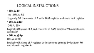
![• ORL addr, A
ORL 25H, A
[25H]– [25H] OR A
Logically OR contents of address with content of A. Store in register A.
• ORL addr, #n
ORL 25H, #30H
[25H]—[25H] OR 30H
Logically OR the contents of address 25h and immediate value 30h.
Store at address 25h.
LOGICAL INSTRUCTIONS](https://image.slidesharecdn.com/microcontrollers-module27-221127132022-f9fd0988/85/MICROCONTROLLERS-module2-7-pptx-61-320.jpg)
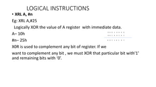
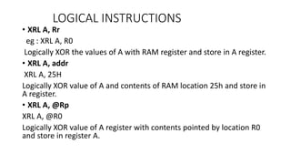
![• XRL addr, A
XRL 25H, A
[25H]– [25H] XOR A
Logically XOR contents of address with content of A. Store in register
A.
• XRL addr, #n
XRL 25H, #30H
[25H]—[25H] OR 30H
Logically XOR the contents of address 25h and immediate value 30h.
Store at address 25h.
LOGICAL INSTRUCTIONS](https://image.slidesharecdn.com/microcontrollers-module27-221127132022-f9fd0988/85/MICROCONTROLLERS-module2-7-pptx-64-320.jpg)

![ CJNE Rr, #n, radd
eg : CJNE R0, #25h, down
Compare R0, with immediate value 25h. If not equal jump to label
down.
CJNE @Rp, #n, radd
eg : CJNE @R0, #25h, down
Compare [R0] with 25h. If not equal jump to down.
PROGRAM CONTROL INSTRUCTIONS](https://image.slidesharecdn.com/microcontrollers-module27-221127132022-f9fd0988/85/MICROCONTROLLERS-module2-7-pptx-83-320.jpg)