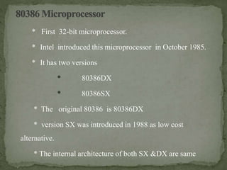
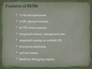
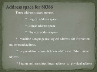
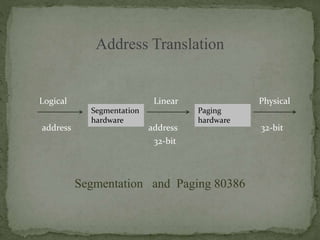
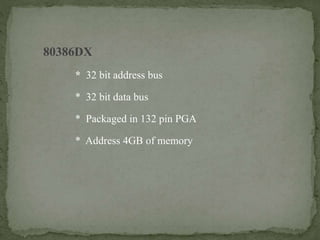
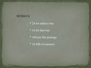
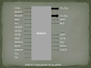
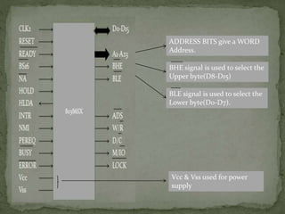
BY
B.ABINAYA BHARATHI,
M.Sc(Cs&IT),
NSCAS.
* First 32-bit microprocessor.
* Intel introduced this microprocessor in October 1985.
* It has two versions
* 80386DX
* 80386SX
* The original 80386 is 80386DX
* version SX was introduced in 1988 as low cost
alternative.
* The internal architecture of both SX &DX are same
80386 has Three operating modes
* Real address mode
* Protected mode
* Virtual 8086 mode
Real address mode:
The real address mode the instruction use real
addresses (similar to 80286).
Protected mode :
The entire instruction set and features are available.
Major features are paging , multitasking and memory
protection.
Virtual 8086 mode (V86 mode) :
This is a special mode within protected mode. This
mode recommend protection and memory management
* 32-bit microprocessor
* 4 GB physical memory
* 64 TB virtual memory
* Integrated memory management unit
* sequential running on multiple OS.
* Instruction pipelining.
* self test feature.
* hardware debugging support.
Three address spaces are used
* Logical address space
* Linear address space
* Physical address space
* Machine Language use logical address for instruction
and operand address.
* Segmentation converts linear address to 32-bit Linear
address.
* Paging unit translates linear address to physical address
Address Translation
Logical Linear Physical
address address 32-bit
32-bit
Segmentation and Paging 80386
Segmentation
hardware
Paging
hardware
80386DX
* 32 bit address bus
* 32 bit data bus
* Packaged in 132 pin PGA
* Address 4GB of memory
CLK2 D0-D31
RESET
READY A2-A31
BS16 BE3
NA BE2
HOLD BE1
HLDA BE0
INTR ADS
NMI W/R
PEREQ D/C
BUSY M/IO
ERROR LOCK
Vcc
GND
PINOUT DIAGRAM OF 80386DX
80386DX
DATABUS -transfers the data
between the microprocessor and
its memory & I/O system.
ADDRESS BUS – address an of the
Memory location.
BANK ENABLE SIGNALS –The
size Of the data is find by the
active bank enable signals.
ADDRESS STATUS – indicate the
Valid address.
W/R Signal -indicate the bus cycle
is read or write type
D/C signal-indicate the bus cycle
Is data or control cycle.
M/IO Signal – indicate the bus
cycle is I/O or Memory bus cycle.
LOCK – indicate the bus cycle is
locked or unlocked
CLOCK Signal –80386 clock
input frequency into 2 and
generates the internal
Processor clock.
NEXT ADDRESS- here
hardware is ready to accept
new data even if the current
Bus cycle not competed.
Interrupt signal used By
external circuit to request a
interrupt
It requests a non-
maskable interrupt it is
done on the earlier versions
of the microprocessor.
The READY input is used to
Synchronize the
microprocessor With the
external hardware.
Initialize the 80386 status start
execution from the address
From the address FFFFFFF0.
Bus size 16 used to select
32-bit data bus ( BS16= 1)
or a 16-bit data bus(BS16 = 0)
Hold is a bus request
it requests a DMA action
HOLDACKNOWLEDGEMENT
Response signal to HOLD state
BUSY indicates the 80386 is
Currently executing a
instruction.
ERROR indicate the when
error is deducted by 80386
While execution.
Vcc for power supply.
PREPROCESSOR EXTENSION
REQUEST indicates the 80386
is ready to transfer data.
80386 was organized as six stages
* Instruction pre-fetch
* Instruction pre-decode
* control
* ALU
* Segmentation and Paging
* Bus Interface unit
16
80386 has 32 registers which are grouped to 7 types
* General Purpose Registers
* Segment Registers
* Instruction Pointer and Flags
* Control Registers
* System Address Registers
* Debug Registers
* Test Registers
There are 9 instruction sets
* Data Transfer
* Arithmetic
* Shift/Rotate
* String Manipulation
* Bit Manipulation
* Control Transfer
* High Level Language Support
* Operating System Support
* Processor Control
BIST
BIST-Built In Self Test
This feature is active when self test is done when
RESET signal is active along with BUSY signal.
80386SX
* 24 bit address bus
* 16 bit data bus
* 100 pin flat package
* 16 MB of memory
CLK2 D0-D15
RESET
READY A1-A23
BS16 BHE
NA BLE
HOLD
HLDA
INTR ADS
NMI W/R
PEREQ D/C
BUSY M/IO
ERROR LOCK
Vcc
Vss
PINOUT DIAGRAM OF 80386SX
80386SX
ADDRESS BITS give a WORD
Address.
BHE signal is used to select the
Upper byte(D8-D15)
BLE signal is used to select the
Lower byte(D0-D7).
Vcc & Vss used for power
supply
THANKYOU

Introduction to 80386

  • 1.
  • 2.
    * First 32-bitmicroprocessor. * Intel introduced this microprocessor in October 1985. * It has two versions * 80386DX * 80386SX * The original 80386 is 80386DX * version SX was introduced in 1988 as low cost alternative. * The internal architecture of both SX &DX are same
  • 3.
    80386 has Threeoperating modes * Real address mode * Protected mode * Virtual 8086 mode
  • 4.
    Real address mode: Thereal address mode the instruction use real addresses (similar to 80286). Protected mode : The entire instruction set and features are available. Major features are paging , multitasking and memory protection. Virtual 8086 mode (V86 mode) : This is a special mode within protected mode. This mode recommend protection and memory management
  • 5.
    * 32-bit microprocessor *4 GB physical memory * 64 TB virtual memory * Integrated memory management unit * sequential running on multiple OS. * Instruction pipelining. * self test feature. * hardware debugging support.
  • 6.
    Three address spacesare used * Logical address space * Linear address space * Physical address space * Machine Language use logical address for instruction and operand address. * Segmentation converts linear address to 32-bit Linear address. * Paging unit translates linear address to physical address
  • 7.
    Address Translation Logical LinearPhysical address address 32-bit 32-bit Segmentation and Paging 80386 Segmentation hardware Paging hardware
  • 8.
    80386DX * 32 bitaddress bus * 32 bit data bus * Packaged in 132 pin PGA * Address 4GB of memory
  • 9.
    CLK2 D0-D31 RESET READY A2-A31 BS16BE3 NA BE2 HOLD BE1 HLDA BE0 INTR ADS NMI W/R PEREQ D/C BUSY M/IO ERROR LOCK Vcc GND PINOUT DIAGRAM OF 80386DX 80386DX
  • 10.
    DATABUS -transfers thedata between the microprocessor and its memory & I/O system. ADDRESS BUS – address an of the Memory location. BANK ENABLE SIGNALS –The size Of the data is find by the active bank enable signals. ADDRESS STATUS – indicate the Valid address.
  • 11.
    W/R Signal -indicatethe bus cycle is read or write type D/C signal-indicate the bus cycle Is data or control cycle. M/IO Signal – indicate the bus cycle is I/O or Memory bus cycle. LOCK – indicate the bus cycle is locked or unlocked
  • 12.
    CLOCK Signal –80386clock input frequency into 2 and generates the internal Processor clock. NEXT ADDRESS- here hardware is ready to accept new data even if the current Bus cycle not competed. Interrupt signal used By external circuit to request a interrupt It requests a non- maskable interrupt it is done on the earlier versions of the microprocessor.
  • 13.
    The READY inputis used to Synchronize the microprocessor With the external hardware. Initialize the 80386 status start execution from the address From the address FFFFFFF0. Bus size 16 used to select 32-bit data bus ( BS16= 1) or a 16-bit data bus(BS16 = 0) Hold is a bus request it requests a DMA action
  • 14.
    HOLDACKNOWLEDGEMENT Response signal toHOLD state BUSY indicates the 80386 is Currently executing a instruction. ERROR indicate the when error is deducted by 80386 While execution. Vcc for power supply. PREPROCESSOR EXTENSION REQUEST indicates the 80386 is ready to transfer data.
  • 15.
    80386 was organizedas six stages * Instruction pre-fetch * Instruction pre-decode * control * ALU * Segmentation and Paging * Bus Interface unit
  • 16.
  • 17.
    80386 has 32registers which are grouped to 7 types * General Purpose Registers * Segment Registers * Instruction Pointer and Flags * Control Registers * System Address Registers * Debug Registers * Test Registers
  • 18.
    There are 9instruction sets * Data Transfer * Arithmetic * Shift/Rotate * String Manipulation * Bit Manipulation * Control Transfer * High Level Language Support * Operating System Support * Processor Control
  • 19.
    BIST BIST-Built In SelfTest This feature is active when self test is done when RESET signal is active along with BUSY signal.
  • 20.
    80386SX * 24 bitaddress bus * 16 bit data bus * 100 pin flat package * 16 MB of memory
  • 21.
    CLK2 D0-D15 RESET READY A1-A23 BS16BHE NA BLE HOLD HLDA INTR ADS NMI W/R PEREQ D/C BUSY M/IO ERROR LOCK Vcc Vss PINOUT DIAGRAM OF 80386SX 80386SX
  • 22.
    ADDRESS BITS givea WORD Address. BHE signal is used to select the Upper byte(D8-D15) BLE signal is used to select the Lower byte(D0-D7). Vcc & Vss used for power supply
  • 23.

Editor's Notes