Download to read offline

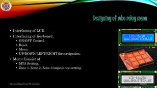
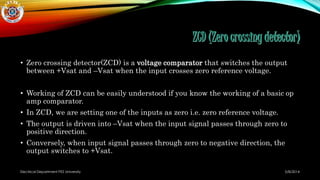
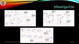
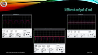
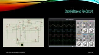


The document discusses the design and simulation of several components for a relay menu including: 1. Interfacing an LCD and keyboard 2. Design and simulation of a zero crossing detector (ZCD) 3. Design and simulation of measuring voltage magnitude