signal generator(pradeep to batch 08)
•Download as PPTX, PDF•
1 like•722 views

This document describes a signal generator circuit that uses the ICL8038 integrated circuit. It explains how the ICL8038 generates repeating electronic signals using two current sources and a comparator to charge and discharge a capacitor in a cycle. It provides the equation to calculate the output frequency based on the capacitor and resistor values. It also lists the typical components used and applications like testing electronic devices and circuits by injecting waveforms.

Recommended
More Related Content
What's hot
What's hot (20)
Similar to signal generator(pradeep to batch 08)
Similar to signal generator(pradeep to batch 08) (20)
Recently uploaded
Recently uploaded (20)
signal generator(pradeep to batch 08)
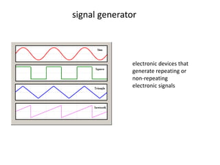
- 1. signal generator electronic devices that generate repeating or non-repeating electronic signals
- 2. ICL8038
- 3. Working of ICL8038 •Capacitor C •Current source #1 •Current source #2 (OFF) •Capacitor charges with current I •Comparator 1 = 2/3 of input voltage •Flip flop is triggered •Current source #2 (ON) current 2I •Capacitor discharges with current I •Comparator 2= 1/3 of input voltage •Flip flop is resetted •Cycle gets repeated
- 4. Comparator
- 5. BUFFER
- 6. function generator circuit using ICL8038 The Frequency output (f) = 0.15/(VR1+R1)C1
- 7. Modified
- 8. Components • Frequency range C1 value 1Hz – 100Hz=1uF 100Hz-1KHz=0.1uF 1KHz-10KHz=0.01uF 10KHz-100KHz=0.001uF • The components list Resistors size 1/4W 5% R1=2.2K R2=10K VR1=10K Single potentiometer Capacitors C1 (above mentioned) Semiconductor IC1=ICL8038=Precision Waveform Generator/ Voltage Controlled Oscillator
- 9. Applications • The waveforms can be injected into a device under test and analyzed as they progress through it, confirming the proper operation of the device or pinpointing a fault in it. • Like Using it to test any measurement equipment, apply signals as input to electronic circuits. • to calibrate a microphone setup.
- 10. Thank you