1. Hydrostatics
1- Fluid pressure
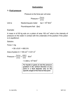
Pressure is the force per unit area
Pressure =
Unit is Newton/square meter bar = 105 N/m2
Pound/square foot (fps)
Example:
A mass m of 50 kg acts on a piston of area 100 cm2 what is the intensity of
pressure on the water in contact with the underside of the position if the piston
is in equilibrium
Solution.
Force = mg
= 50 x 9.81 = 490.5 N
Area of piston A = 100 cm2 = 0.01 m2
Pressure = = N/m2
= 4.905 x 10⁴ N/m2
For liquids or gases at rest the pressure
gradient in the vertical direction at any
point in a fluid depends only on the
specific weight of the fluid at that point
Dr. Adel Afify 1 MET 212
2. 2- Pascal's Law for Pressure at a Point
Triangular prismatic element of fluid
acts perpendicular to surface ABCD,
acts perpendicular to surface ABFE and
acts perpendicular to surface FECD.
And, as the fluid is at rest, in equilibrium, the sum of the forces in any direction
is zero.
Pressure at any point is the same in all directions.
This is known as Pascal's Law and applies to fluids at rest.
Dr. Adel Afify 2 MET 212
3. 3. Variation of pressure vertically in a fluid under gravity
Vertical elemental cylinder of fluid
The fluid is at rest and in equilibrium so all the forces in the vertical direction
sum to zero. We have
Taking upward as positive, in equilibrium we have
Thus in a fluid under gravity, pressure decreases with increase in height .
Dr. Adel Afify 3 MET 212
4. 4- pressure head Free surface (pressure = p0)
Z p2
z2 h = z2 – z1
p1
z1
y
X
p1 - p2 = ρgh
h = pressure head
Dr. Adel Afify 4 MET 212
5. example:
A diver is working at a depth of 18 m below the surface of the sea. How much
greater is the pressure intensity at this depth than at the surface? Specific
weight of sea water is 10000 N/m3
Solution:
p1 - p2 = ρgh
Δ p = 10000 x 18
Δ p=180000 N/m2
Example:
Find the head height (h) of water corresponding to an intensity of pressure (p)
of 340000 N/m2. The specific weight of water is 9.81 x 10³ N/m3
Solution:
p = ρgh
h= h= = 34.7 m
The hydraulic jack
F1 = PA1 F2 = PA2
Dr. Adel Afify 5 MET 212
6. Example: If the force F1 is 850 N is applied to the smaller cylinder of a
hydraulic jack. The area A1 of a small piston is 15 cm2 and the area A2 of the
large piston is 150 cm2. What load can be lifted on the larger piston? The
specific weight of the liquid in the jack is 9.81 x 10³ N/m3
Solution:
F1 = PA1
850 = P (15/10000) P = 5.667 X 10⁵ N/m2
F2 = PA2
F2 = 5.667 X 10⁵ N/m2 X (150/10000) F2 = 8500 N
Mass of lifted = Mass of lifted = = 866.5 kg
Dr. Adel Afify 6 MET 212
7. Measurement of pressure
Pressure
1
Gage pressure @ 1
Local atmospheric
Pressure reference
Absolute pressure @ 1
2 Gage pressure @ 2
Pressure is designated as either absolute pressure or gage pressure
A barometer is used to measure atmospheric pressure
Absolute pressure = gauge pressure + atmospheric pressure
Gauge pressure is
Absolute pressure is
Example:
A mountain lake has an average temperature of 10 0c and a maximum depth of
40 m. for a barometric pressure of 598 mm Hg. Determine the absolute
pressure (in Pascal’s) at the deepest part of the lake.
Solution:
Dr. Adel Afify 7 MET 212
8. P = Ϫ H2O h + p0
p0 is the pressure at the surface
p0 = Ϫ Hg h
p0 = (133 kN/m3) (0.598m) = 79.5 kN/m2
P = Ϫ H2O h + p0
P = (9.81x1000 N/m3)(40 m) + 79.5 5 kN/m2
= 392. 5 kN/m2 + 79.5 5 kN/m2
= 472 kN/m2 = 472 kpa (abs)
Manometer
1- Piezometer tube
Consists of a vertical tube, open at the top, and attached to the container in
which the pressure is desired
P = Ϫ h + p0
Pressure will increase as we move downward
And will decrease as we move upward
A simple piezometer tube manometer
Dr. Adel Afify 8 MET 212
9. Example:
A pressure tube is used to measure the pressure of oil (mass density ρ = 640
kg/m3) in a pipeline. If the oil rises to a height of 1.2 m above the center of the
pipe, what is the gage pressure in N/m2 at that point?
Solution:
P=Ϫ h
P=ρgh
P = (640 kg/m3) x (9.81 m/s2) x (1.2 m)
P = 7.55 kN/m2
2- U- Tube manometer
Pressure in a continuous static fluid is the same at any horizontal level so,
Dr. Adel Afify 9 MET 212
10. For the left hand arm
For the right hand arm
As we are measuring gauge pressure we can subtract giving
Example:1
What will be the (a) the gauge pressure and (b) the absolute pressure of
water at depth 12m below the surface? ρwater = 1000 kg/m3, and p atmosphere =
101kN/m2.
a)
b)
Example:2
At what depth below the surface of oil, relative density 0.8, will produce a
pressure of 120 kN/m2? What depth of water is this equivalent to?
Dr. Adel Afify 10 MET 212
11. a)
b)
Example:3
What would the pressure in kN/m2 be if the equivalent head is measured
as 400mm of (a) mercury relative density =13.6 (b) water ( c) oil specific
weight 7.9 kN/m3?
a) Mercury
b) Water
c) Oil
Dr. Adel Afify 11 MET 212
12. Example 4
A manometer connected to a pipe indicates a negative gauge pressure of
50mm of mercury. What is the absolute pressure in the pipe in Newton’s
per square meter is the atmospheric pressure is 1 bar?
Example 5
What height would a water barometer need to be to measure atmospheric
pressure?
Measurement of pressure difference by using a "U"-Tube
Manometer.
Dr. Adel Afify 12 MET 212
13. Pressure difference measurement by the "U"-Tube manometer
Example
In the figure below two pipes containing the same fluid of density ρ= 990 kg/m are
3
connected using a u-tube manometer. What is the pressure between the two pipes if
the manometer contains fluid of relative density13.6
h1 = 1.5 m , h2 = 0.5 m , h3 = 0.76 m & ρ2 = SG * ρwater
Dr. Adel Afify 13 MET 212
14. ρ2 = 13.6 * 1000 kg/m3
Ϫ 1 = ρ1g = 990 * 9.81 = 9711.9 N/m3
Ϫ 2 = ρ2 g = 13.6 * 1000 * 9.81 = 133416 N/m3
pC = pD
pC = pA + g hA
pD = pB + g (hB - h) + man g h
pA - pB = g (hB - hA) + hg(man - )
= 990 x9.81x(0.75-1.5) + 0.5x9.81 x(13.6-0.99) x 103
= -7284 + 61852
= 54 568 N/m2 (or Pa or 0.55 bar)
Forces on Submerged Surfaces in Static Fluids
1. Fluid pressure on a surface
Pressure is defined as force per unit area. If a pressure p acts on a small area then the
force exerted on that area will be
Since the fluid is at rest the force will act at right-angles to the surface.
General submerged plane
Consider the plane surface shown in the figure below. The total area is made up of many
elemental areas. The force on each elemental area is always normal to the surface but, in
general, each force is of different magnitude as the pressure usually varies.
Dr. Adel Afify 14 MET 212
15. We can find the total or resultant force, R, on the plane by summing up all of the forces on
the small elements i.e.
This resultant force will act through the centre of pressure, hence we can say
If the surface is a plane the force can be represented by one single resultant force,
acting at right-angles to the plane through the centre of pressure.
Horizontal submerged plane
For a horizontal plane submerged in a liquid (or a plane experiencing uniform pressure over
its surface), the pressure, p, will be equal at all points of the surface. Thus the resultant force
will be given by
Curved submerged surface
If the surface is curved, each elemental force will be a different magnitude and in different
direction but still normal to the surface of that element. The resultant force can be found by
resolving all forces into orthogonal co-ordinate directions to obtain its magnitude and
direction. This will always be less than the sum of the individual forces, .
2. Resultant Force and Centre of Pressure on a submerged plane surface in a
liquid.
This plane surface is totally submerged in a liquid of density and inclined at an angle of
to the horizontal. Taking pressure as zero at the surface and measuring down from the
surface, the pressure on an element , submerged a distance z, is given by
Dr. Adel Afify 15 MET 212
16. and therefore the force on the element is
The resultant force can be found by summing all of these forces i.e.
(assuming and g as constant).
The term is known as the 1st Moment of Area of the plane PQ about the free surface.
It is equal to i.e.
where A is the area of the plane and is the depth (distance from the free surface) to the
centroid, G. This can also be written in terms of distance from point O ( as )
The resultant force on a plane
This resultant force acts at right angles to the plane through the centre of pressure, C, at a
depth D. The moment of R about any point will be equal to the sum of the moments of the
forces on all the elements of the plane about the same point. We use this to find the
position of the centre of pressure.
It is convenient to take moments about the point where a projection of the plane passes
through the surface, point O in the figure.
We can calculate the force on each elemental area:
And the moment of this force is:
Dr. Adel Afify 16 MET 212
17. are the same for each element, so the total moment is
We know the resultant force from above , which acts through the centre of
pressure at C, so
Equating gives,
Thus the position of the centre of pressure along the plane measure from the point O is:
It look a rather difficult formula to calculate - particularly the summation term. Fortunately this
term is known as the 2nd Moment of Area , , of the plane about the axis through O and it
can be easily calculated for many common shapes. So, we know:
And as we have also seen that 1st Moment of area about a line through O,
Thus the position of the centre of pressure along the plane measure from the point O is:
and depth to the centre of pressure is
How do you calculate the 2nd moment of area?
To calculate the 2nd moment of area of a plane about an axis through O, we use the parallel
axis theorem together with values of the 2nd moment of area about an axis though the
centroid of the shape obtained from tables of geometric properties.
The parallel axis theorem can be written
Dr. Adel Afify 17 MET 212
18. where is the 2nd moment of area about an axis though the centroid G of the plane.
Using this we get the following expressions for the position of the centre of pressure
The second moment of area of some common shapes.
The table blow given some examples of the 2 nd moment of area about a line through the
centroid of some common shapes.
2nd moment of area, , about
Shape Area A
an axis through the centroid
Rectangle
Triangle
Circle
Semicircle
Dr. Adel Afify 18 MET 212
19. Example: 1
The 4- m diameter circular gate is located in the inclined wall of a large reservoir containing
water (Ϫ = 9.8 kN/m3). The gate is mounted on a shaft along its horizontal diameter. For a
water depth of hc = 10 m above the shaft determine: (a) the magnitude and location of the
resultant force exerted on the gate by the water. (b) the moment that would have to be
applied to the shaft to open the gate.
Solution
F = Ϫ hc A
F = 9.8 X 103 X 10 X (4π)
F = 1230 X 103 N
m
A = π R2 = π (22) = 12.57 m2
IGG = R4 = 12.567
Sc = +11.55 = 11.637 m
D = Sc * sin 60
D = 11.637 * sin60 = 10.0775 m
(b) the moment
M = F * (Sc – X)
M = 1230 X 103 * (11.637 – 11.55)
M = 1.07 X 10⁵ N . m
Example: 2
Determine the resultant force due to the water acting on the 1m by 2m rectangular area AB
shown in the diagram below.
Dr. Adel Afify 19 MET 212
20. The magnitude of the resultant force on a submerged plane is:
R = pressure at centroid area of surface
This acts at right angle to the surface through the centre of pressure.
By the parallel axis theorem (which will be given in an exam), , where IGG is
the 2nd moment of area about a line through the centroid and can be found in tables.
For a rectangle
As the wall is vertical, ,
Dr. Adel Afify 20 MET 212
21. Example: 3
Determine the resultant force due to the water acting on the 1.25m by 2.0m triangular area
CD shown in the figure above. The apex of the triangle is at C.
For a triangle
Depth to centre of gravity is .
Distance from P is
Distance from P to centre of pressure is
Forces on submerged surfaces
Example: 4
Obtain an expression for the depth of the centre of pressure of a plane surface wholly
submerged in a fluid and inclined at an angle to the free surface of the liquid.
A horizontal circular pipe, 1.25m diameter, is closed by a butterfly disk which rotates about a
horizontal axis through its centre. Determine the torque which would have to be applied to
Dr. Adel Afify 21 MET 212
22. the disk spindle to keep the disk closed in a vertical position when there is a 3m head of fresh
water above the axis.
Answer:
The question asks what is the moment you have to apply to the spindle to keep the disc
vertical i.e. to keep the valve shut?
So you need to know the resultant force exerted on the disc by the water and the distance x
of this force from the spindle.
We know that the water in the pipe is under a pressure of 3m head of water (to the spindle)
Diagram of the forces on the disc valve, based on an imaginary water surface.
, the depth to the centroid of the disc
h' = depth to the centre of pressure (or line of action of the force)
Calculate the force:
Calculate the line of action of the force, h'.
Dr. Adel Afify 22 MET 212
23. By the parallel axis theorem 2nd moment of area about O (in the surface)
where IGG is the 2nd moment of area about a line through the centroid of the disc and IGG =
4
r /4.
So the distance from the spindle to the line of action of the force is
And the moment required to keep the gate shut is
Dr. Adel Afify 23 MET 212