Downloaded 220 times


![9/4/2012
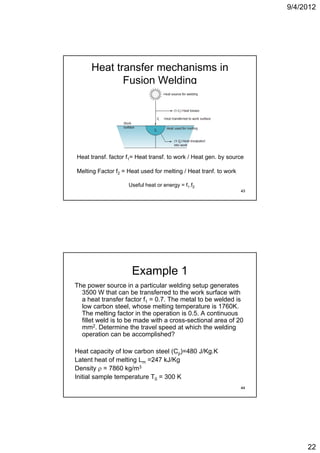
Example 1-Solution
Rate of heat input to the weld bead = 3500 × f1 × f2
= 3500 × 0 7 × 0 5 = 1225 J/s
0.7 0.5
Heat input = Energy used for heating to Tm + Energy used
for melting
1225 = [Cp(Tm-T0) + Lm ] × A × v
1225 = [480(1760 300) + 247 ×103] × 7860 × 20 ×10-6 × v
[480(1760-300) 10 10 6
Travel speed v = 0.0082 m/s = 8.2 mm/s
45
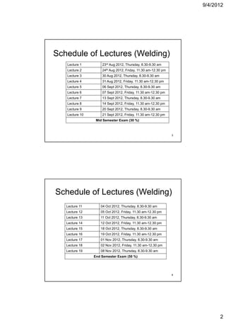
Summary: Lectures 1-3
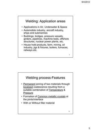
• Overview of welding, applications,
ad a tages
advantages
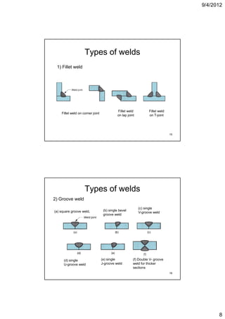
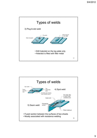
• Welded Joint types
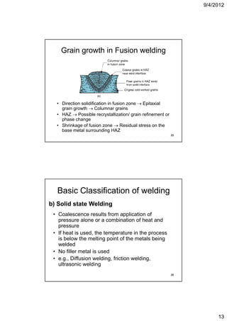
• Fusion & Solid state welding
• Elements of weld setup, Heat Balance,
Power density y
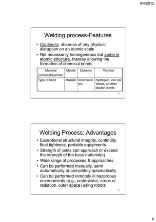
• N.B: Characteristics, micro-structural
zones and concept of lattice continuity in
fusion & solid state welding
46
23](https://image.slidesharecdn.com/weldinglectures1-4-121005013434-phpapp02/85/Welding-lectures-1-4-23-320.jpg)


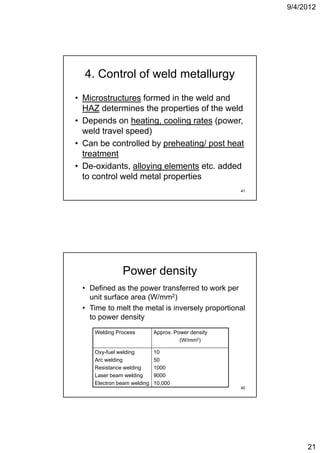
- Heating rate and peak temperature - Cooling rate - Composition of filler metal - Pre/post heating of base metal - Stress relieving heat treatment Controls the microstructure and properties of the weld. 41 Heat transfer in welding process - Heat input to the weld is from the energy source - Heat is conducted away from the weld zone into the base metal - Heat flow depends on thermal properties of base metal and weld metal - Heat affected zone experiences thermal cycle due to heat input - Rapid heating and cooling rates in welding leads to non-equilibrium microstructures - Control of heat input and cooling rate is important to control weld metallurgy


![Types%20of%20 Welding[1]](https://cdn.slidesharecdn.com/ss_thumbnails/types20of20welding1-091203225849-phpapp02-thumbnail.jpg?width=640&height=640&fit=bounds)


![423%20outline%202011[1]](https://cdn.slidesharecdn.com/ss_thumbnails/42320outline2020111-120218000422-phpapp01-thumbnail.jpg?width=640&height=640&fit=bounds)


